SlideShare ist ein Scribd-Unternehmen logo
1 von 10
Downloaden Sie, um offline zu lesen
Telefax 0 72 61-92 63-33
e-mail: info@eug-grob.de
1
Betriebsanweisung
Operationsinstruction
Elektrozylinder
Electrocylinder
Baugruppen
Devices
Elektrische Anschlüsse / Electric Cable Connections - Gland positions
Hubeinheit
Actuator
Planetengetriebe
Planetary gearbox
Motorbremse
Motor brake
Motorbremse PG9
Motor brake PG9
Endschalter PG9
Limit Switch PG9
Potentiometer
Potentiometer
Grob-Motor
Grob-Motor
Potentiometer /
Drehimpulsgeber PG9
Potentiometer /
Rotary encoder PG9
Motor PG9 (EZ10)
PG11 (EZ20, 30)
Motor PG9 (EZ10)
PG 11 (EZ20, 30)
Hubeinheit
Actuator
Endschalter PG9
Limit Switch PG9
Motorbremse PG9
Motor brake PG9
Grob-Motor
Grob-Motor
Motor PG9 (EZ10)
PG11 (EZ20, 30)
Motor PG9 (EZ10)
PG 11 (EZ20, 30)
Potentiometer /
Drehimpulsgeber PG9
Potentiometer /
Rotary encoder PG9
Potentiometer
PotentiometerMotorbremse und / oder
Impulsgeber
Motor brake and / or
encoder
Telefax 0 72 61-92 63-33
e-mail: info@eug-grob.de
2
Technische Beschreibung
1.0 Aufbau
Höchste Flexibilität bzw. Ausbaufähigkeit und der sich
ergebende hohe Nutzwert kennzeichnen die Typenreihe
Elektrozylinder. Elektrozylinder ist überwiegend für den
industriellen Einsatz konzipiert und deshalb besonders
robust und mit hohen Sicherheitsstandards ausgerüstet,
sowie in allen Einbaulagen zuverlässig betriebsfähig. Die
hohe Wirtschaftlichkeit über alle Optionen wurde durch eine
maximale Integration aller Funktionen im Design der Alu-Profile
erreicht. Das Hubprofil (Alu-Profil) hat Gebrauchsmusterschutz
unter der Nr. 295 05 749.1
1.1 Kolbenrohr
Das Kolbenrohr (geschliffen und hartverchromt) ist im
Standard gegen Verdrehung gesichert. Die selbstzentrierende
Verdrehsicherung vermeidet unter Last unerwünschte innere
Radialkräfte.
1.2 Anschlußköpfe
Diverse Anschlußköpfe sind ab Lager lieferbar (siehe techn.
Ausführungen).
1.3 Spindelarten
Sämtliche Antriebe können mit Trapezgewindespindel nach DIN
103, 7e oder mit Kugelgewindespindel ausgeführt werden. Die
Ausführung “Trapezgewinde” kann wahlweise mit Bronze- oder
Kunststoffspindelmutter geliefert werden.
2.0 Getriebe-Ausführungen
Grob-Planetengetriebe 1-, 2- oder 3-stufig
(siehe Leistungstabellen)
3.0 Endabschaltung / Positionierung
Bei der Endabschaltung bzw. Positionierung sind fol-gende 3
Varianten möglich:
1. elektromechanisch mit zwei von außen
verstellbaren Endschaltern
Der Hub kann, vom Nennhub ausgehend, um 20 mm
vergrößert bzw. um 30 mm verkleinert werden (siehe
Einstellanleitung Seite 16)
2. elektromechanisch mit zwei von außen
verstellbaren Endschaltern und zwei Sicher-
heitsendschaltern (Zwangstrenner).
Bewirkt eine längere Baulänge. (Option)
Der Hub kann, vom Nennhub ausgehend, um 20mm
vergrößert bzw. um 30mm verkleinert werden werden (siehe
Einstellanleitung Seite 16)
3. stufenlos-sensorisch mit im Profil des
Hubgehäuses integrierten, außenliegend
geführten und frei zugänglichen
Magnetschaltern (Reedkontakten). (Option)
Variante 3 ist selbstverständlich auch mit Variante 1
kombinierbar.
4.0 Motoren
Folgende Motoren können verwendet werden:
1. Grob-Drehstrommotor (Standard)
2. Grob-Wechselstrommotor (Option)
3. Gleichstrommotor in Vorzugsspannung 24 Volt
(Permanentmagnet) (Option)
4. Servomotorflansch
(zum Anbau von Servomotoren) (Option)
5.0 Zuverlässigkeit und Qualitätssicherung
Jeder Antrieb wird auftrags- bzw. kundenspezifisch gefertigt
und unter “Last” geprüft. Sämtliche Bauteile bzw. Baugruppen
unterliegen strengen Kontrollen nach DIN EN ISO 9001 : 2000
und werden (in der Regel bevorratet) aus einer EDV-gesteuerten
Lagerhaltung der Endmontage zugeführt.
Technical Description
1.0 Design
The new Electrocylinder range was developed to offer the designer
and user an extremely cost effective, flexible and modular design of
actuatorofdurablequalityataneconomicalprice.TheElectrocylinder
series, covering thrust forces of 160N up to 40,000N is principally
intended for industrial applications. The actuators are therefore
of robust construction and designed with a high safety factor, so as
to be able to operate reliably in any position. The Electrocylinder
range employs special registered design aluminium profiles (ref No
29505749.1) which are an integral part of the function of the electric
actuator and it’s drive components.
1.1 Push Rod
The push rod (hard chromed and polished) is provided as standard
with an anti-rotation guide within the aluminium profile. The self-
centring guide prevents radial forces being generated under load
and improves the mechanical efficiency.
1.2 End connection and mounting options.
Numerous options are available as standard components - refer
technical data sheets.
1.3 Spindle types
All types can be fittelwith leadt screw to DIN 103, 7e or ball
screw. alternatively G9 DIN 286 (130µm/300mm) can be fitted.
The standard acme lead screw can be fitted optionally with
bronze or plastic nut.
2.0 Gearing Options
Grob - Planetary gear box 1/2/3 stage
3.0 Limit switches / Linear positioning
For end-of-stroke switching or linear position control there are
3 variants:
1. Two adjustable internal electro-mechanical
limit switches.
Based on the nominal stroke it’s possible to increase
the stroke about 20mm or to reduce it about 30mm (see
adjustment instructions page 16).
2. Two adjustable internal electro-mechanical
limit switches as well as two fixed position
safety limit switches (forcec separators).
Results in a longer actuator. (option)
Based on the nominal stroke it’s possible to increase
the stroke about 20mm or to reduce it about 30mm (see
adjustment
instructions page 16).
3. Two adjustable proximity switches fitted to an
external slideway integrated in the aluminium
profile (positioning and safety limit switches).
(Option)
Variant 3 can be combined with variant 1 of course.
4.0 Electric Motors
The following motors are available:
1. Grob three phase motor (Standard)
2. Grob A.C. motor (Option)
3. DC Motor preferred tension 24V
(permanent magnet) (Option)
4. Servo motor flange
(Attachment for servomotors) (Option)
5.0 Reliability and quality assurance
Every drive is manufactured in accordance with the order and
customer´ s specifications and is tested under “load”. Our
components and subassemblies are subjected to stringent
inspections according ISO 9001 and are normally in stock,
being taken from a computer-controlled warehouse for final
assembly. Refer to the “Individual descriptions” for detailed lists
and explanations.
Telefax 0 72 61-92 63-33
e-mail: info@eug-grob.de
3
6.0 Bestimmungsgemäße Verwendung
Verwenden Sie den Antrieb ausschließlich zum Antreiben von
Maschinen, Vorrichtungen und Anlagen, die eine mittelbare
oder unmittelbare Gefährdung von Personen ausschließen
und bei einer Umgebungstemperatur von 0-60°C. Eine
Personenbeförderung ist ohne vorherige Rücksprache mit dem
Hersteller (oder der zuständigen Vertretung) nicht zulässig.
Ist eine mittel- oder unmittelbare Gefährdung von Personen
nicht auszuschließen, müssen zwingend zusätzliche
Maßnahmen (Abdeckung, Absperrung, usw.) getroffen werden,
die das Risikopotential ent-sprechend minimieren. Verwenden
Sie den Antrieb nicht in explosionsgefährdeten Räumen. Stellen
Sie sicher, dass der Antrieb nicht überlastet werden kann.
7.0 Empfehlung
Durch Verwendung eines gefederter Anschlußkopfes (Option)
können Stoßbelastungen gedämpft werden. Generell sollte
bei der Festlegung der Antriebsgröße genügend Sicherheit
einbezogen werden.
8.0 Optionen
Folgende zusätzliche Optionen sind wählbar:
1. Zwei sensorische Betriebsendschalter
(Magnetschalter; Reed-Kontakt) mit/ohne
zwei zusätzlich 2 Endschalter
2. Befestigungsarten: A/B/C/D
(siehe ”Kombinationsmöglichkeiten” S. 18)
3. Anschlußköpfe
(siehe ”Kombinationsmöglichkeiten” S. 18)
4. Bremse
5. Verschiedene Versionen Wendelpotentiometer
oder Drehimpulsgeber
6. Kolbenrohr aus Edelstahl Nr. 1.4301
DIN 2462 (Nirosta)
7. Flansche zum Anbau der gängigsten Servomotoren
8. Kunststoff-Spindelmutter zur Erzielung
von hoher Lebensdauer bei reduzierter Last.
9. Flansche zum Anbau der gängigsten Servomotoren
10. Kunststoff-Spindelmutter zur Erzielung von hoher
Lebensdauer bei reduzierter Last.
6.0 Conditions of use
It is a condition of sale that MORAT components shall not
be used for the movement of loads whereby persons can be
directly or indirectly endangered. The application of MORAT
linear actuators in equipment which is intended for the
transport of passengers is only permissable after prior written
consultation and the agreement of the manufacturer MORAT
or their represantatives. We would refer users of actuators to
safety rules, regulations and laws governing the protection of
personnel working in the area of moving equipment and to
the need for protective guards or barriers. Similarly-protective
measures are required where suspended loads are involved.
7.0 Special protective measures
It is possible to bring the linear actuators to a high safety
standard by using the following option:
1. elastic connection head (option)
(for absorbing shock load)
Generally the actuator size chosen should be sufficiently
enough.
8.0 Options
The following additonal options can be chosen:
1. Two sensoric operating limit switches
(solenoid switch; Reed contact)
with/without two safety limit switches.
2. Mounting types: A/B/C/D
(see system configuration P. 18)
3. Connecting heads (see system configuration P. 18)
4. Bellows
5. Brake
6. Helical potentiometer. (only version A and P),
torque counter etc.
7. Increased service life with the same output:
Next largest size, or with the same size via
output reduction.
8. Piston tube (Stainless steel No. 1.4301 DIN 2462)
9. Servo flange for attachment of most
common servomotors.
10. Plastic spindle nut, high service life in case of
reduced load.
Technische Beschreibung Technical Description
Einbau- und Betriebsanleitung Installation & Operation
1.0 Sicherheitshinweise
• Lesen Sie vor der Montage bzw. Inbetriebnahme
alle Dokumente sorgfältig durch und halten Sie die
Anweisungen dieser Einbau- und Betriebsanleitung genau
ein.
2.0 Dokumentation
Im Katalog sind alle erforderlichen Dokumente enthalten.
Sie können jedoch folgende Unterlagen erxtra anfordern:
• Elektro-Anschlussplan
• Technische Beschreibung
2.1 Kabellänge
Die Standard-Kabellänge beträgt 1,5 m. elektrisc
3.0 Aufstellung, Anbau und elektrische Inbetriebnahme
1.0 Attention:
All documentation supplied is to be carefully studied
before installation and start-up. Installation and electrical
connection of the equipment should be made by qualified
personnel! Important technical data is given on adhesive
foil attached to the actuator.
2.0 Documentation
The complete documentation is in the main catalogue
Available in doc file is:
• Set product discription
• Electrical connection diagram
2.1 Connecting cable tails
The standard length of cable provided is appr. 1.5 meters.
3.0 Installation and Commissioning
Telefax 0 72 61-92 63-33
e-mail: info@eug-grob.de
4
Einbau- und Betriebsanleitung Installation & Operation
3.1 Aufstellung und Anbau
Tragen Sie bei Transport und Montage des Antriebes
Sicherheitsschuhe. Ein herabfallender Antrieb kann
Verletzungen hervorrufen. Montieren Sie den Antrieb ohne
Verspannungen. Anbauteile dürfen nicht durch Stöße oder
Schläge montiert werden.
Die Festigkeitsklasse der Befestigungsschrauben muß min.
8.8 sein.
Die verstellbaren Befestigungsarten B und C müs-
sen symmetrisch zueinander angeordnet sein. Die
Befestigungsschrauben müssen mit dem vorgeschriebenen
Anzugsmoment angezogen werden:
EZ - Typ 10 = 3Nm,
EZ - Typ 20 = 10Nm,
EZ - Typ 30 = 25Nm
3.2 Elektrische Inbetriebnahme
• Stellen Sie vor der Inbetriebnahme sicher, dass die
Stromzufuhr unterbrochen und gegen unbeabsich-tigtes
Einschalten gesichert ist.
• Schließen Sie den Antrieb nur an ein Netz mit funk-
tionierendem Schutzleiter an.
• Lesen Sie den Schaltplan sorgfältig durch und achten
Sie auf die richtige Betriebsspannung (siehe auch
Typenschild auf dem Antrieb)
• Alle herausgeführten Kabel sind nach Schaltplan an-
zuschließen. Werden Endschalter und/oder Motor-
Thermoschutz nicht angeschlossen, kann der Antrieb
zerstört werden. Der Thermoschutz soll im Fehlerfall den
Antrieb stromlos schalten (Öffner)
Achtung! Beim Absinken der Temperatur schaltet der
Antrieb selbsttätig wieder ein (Bimetal).
• Prüfen Sie durch Tip-Betrieb die Hubrichtung. Um die
Hubrichtung umzukehren tauschen Sie zwei Phasen der
Netzleitung.
• Die Antriebe werden standardmäßig in der Schutzart
IP54 ausgeliefert.
Die Antriebe der Baureihe Elektrozylinder 10, 20, 30
haben in Sonderausführung zusätzlich Sicherheits-
endschalter (Zwangstrenner) nach VDE 0113, welche den
Antrieb vor Zerstörung bewahren. Ist der Antrieb auf die
Sicherheitsendschalter aufgelaufen, kann die Unterbrechung
des Stromkreises durch Drehen der Motorwelle über einen
Innensechskant bzw. durch ein Handrad (Option) freigeschalten
werden.
Ebenfalls kann durch Verstellen der Endschalter in Richtung
Hubvergrößerung (s. Einstellanleitung) die Freigabe erfolgen,
sofern nicht bereits die max. Hublänge eingestellt ist.
(Elastomerdämpfung in den Endlagen bietet zusätzlichen
mechanischen Schutz).
4.0 Wichtige Hinweise
4.1 Blockierung des Kolbenrohres
Bei häufiger Blockierung des Kolbenrohres durch zu hohe
Hubkraft bzw. Auffahren gegen Festanschlag besteht die
Gefahr einer Beschädigung des Antriebes! Notpuffer aus
Elastomer sind in den Endlagen integriert und nur für den
Notfall vorgesehen.
4.2 Besondere Schutzeinrichtungen
Durch den Einsatz eines gefederter Anschlußkopf (Option)
kann der Antrieb auf einen höheren Sicher-heitsstandard
gebracht werden:
Generell sollte bei der Festlegung der Antriebsgröße genügend
Sicherheit einbezogen werden.
3.1 Notes for the mechanical installation
To ensure a trouble free and long working life of the actuator, the
following should be noted:
The force applied through the thrust tube should be axial to the
actuator. If in doubt it is always better to employ rod eye - rod
eye, or rod eye - trunnion mounting.
The installed position should not be pre-loaded in any way.
The piston rod has as standard an internal anti-rotation guide
(this can be omitted if preferred).
The mounting options B (adjustable Trunnion) and C (adjustable
brackets) should be fixed symetrically. The fixing screws are to
be tightened to the following torque settings:
EZ - Type 10 = 3 Nm
EZ - Type 20 = 10Nm
EZ - Type 30 = 25Nm
3.2 Notes for Electrical installation
The following points are to be noted:
All cables from the actuator are to be correctly connected
according to the wiring diagrams.
The correct matching supply voltage is to be checked.
After connection, check that travel direction is correctly signaled
by ”jogging”.
Should the direction be incorrect the cable connections are to be
changed (or current phase).
The standard Elektrozylinder are fitted with safety end-switches
(current breaker) in accordance with VDE 0113, designed to
prevent damage to the equipment. If the linear movement is
driven to the safety switch, thereby opening the circuit, an Allen
Key socket is provided for turning the motor until this is again
closed (there is also a fixed hand-wheel option).
The closing can also be effected by adjusting the limit switches
into direction of larger stroke if the max. stroke lenght hasn’t
been set (additional mechanical protection of final positions by
elastomeric damping).
4.0 Safety Measures
4.1 Blocking of thrust tube
Elastomer buffers are fitted internally within the actuator to limit
damage if the actuator is driven to the mechanical stroke limit. If
however, this occurs repeatedly or the actuator is driven to a rgid
stop, this can lead to blocking of the screw nut and mechanical
damage.
4.2 Conditions of use
It is a condition of sale that Grob components shall not be used
for the movement of loads whereby persons can be directly or
indirectly endangered. The application of Grob linear actuators
in equipment which is intended for the transport of passengers
is only permissable after prior written consultation and the
agreement of the manufacturer Grob or their represantatives.
We would refer users of actuators to safety rules, regulations
and laws governing the protection of personnel working in the
area of moving equipment and to the need for protective guards
or barriers. Similarly-protective measures are required where
suspended loads are involved.
Telefax 0 72 61-92 63-33
e-mail: info@eug-grob.de
5
4.3 Umgebungstemperaturen, Kondenswasser
Halten Sie mit dem Hersteller Rücksprache, wenn ein
Einsatz unter 0°C vorgesehen ist. Bei Minustemperatur muß
mit einem verzögerten Anlaufverhalten gerechnet werden.
Im Tieftemperaturbereich müssen grundsätzlich geeignete
Anschlußkabel verwendet werden.
Bei ständig wechselnden Temperaturen wird die Bildung von
Kondenswasser begünstigt. Ebenso bei Einsatz außerhalb von
Gebäuden, bzw. bei hoher Luftfeuchtigkeit. Das werksseitige
Anbringen von Kondenswasserbohrungen (ø 2 mm) unter
Angabe der jeweiligen Einbaulage (in Verbindung mit einer
Feuchtschutzlackierung von Rotor und Stator) bewirkt eine
deutliche Verbesserung.
Achtung! Durch die Kondenswasserbohrung wird die
standardmäßige Schutzart (IP54) beeinträchtigt.
Eine Dauerbeheizung des Getriebes erfüllt den gleichen Zweck.
Beaufschlagen Sie hierzu eine Phase der Netzleitungen mit
Strom wenn der Antrieb stillsteht. Das Antrieb bleibt dadurch
im Bereich von ca. 30°C. Da je nach Motortyp unterschiedliche
Spannungen erforderlich sind, ist unbedingt Rücksprache mit
dem Hersteller oder der zuständigen Vertretung zu halten.
Bremsen Sie den Antrieb nicht durch Umpolen der
Netzleitungen, die Lebensdauer verringert sich sonst erheblich.
5.0 Wartung und Schmierung
5.1 Schmierung von Anschlußkopf und Hubprofil
Die Antriebe sind bei Auslieferung mit einer Langzeitschmierung
ausgerüstetundbesitzeneinenSchmiernippelamAnschlußkopf.
Hier sollte nach ca. 500 Doppelhüben eine Nachschmierung
mit ca. 3 bis 6 Gramm Schmierstoff (siehe Schmierstoffangabe)
vorgenommen werden.Auch in der Mitte des Hubprofils befindet
sich ein Schmiernippel. Dieser sollte ebenfalls nach ca. 5.00
Doppelhüben (bei ausgefahrenem Kolbenrohr) nachgeschmiert
werden. Dadurch wird die Lebensdauer wesentlich erhöht. Von
Zeit zu Zeit sollte - je nach Einsatzfall - das Kolbenrohr mit
einem geölten Tuch gereinigt werden.
5.2 Verschleiß der Spindel
Bei festgestelltem Verschleiß der Trapez- oder Kugel-
gewindespindel bzw. Spindelmutter empfiehlt sich ein
kompletter Austausch im Herstellerwerk. Da diese Teile
je nach Belastungsart und Hubgeschwindigkeit einem
natürlichen Verschleiß unterliegen, wird empfohlen, frühzeitig
einen Ersatzantrieb (Austauschantrieb) beim Herstellerwerk/
Vertretung zu ordern.
5.3 Garantieanspruch und Reparatur
Alle Antriebe werden vor der Auslieferung einem eingehenden
Probelauf unterzogen und entsprechend den Bestelldaten
geprüft und mit dem Zeichen versehen. Während
der Garantiezeit darf der Antrieb nicht geöffnet werden.
Eine Demontage entbindet den Hersteller von jeglicher
Garantieleistung.
Im Reparaturfall senden Sie den Antrieb an den Hersteller
oder eine geeignete Vertretung zurück. Gegen Berechnung
kann vom Hersteller kurzfristig eine Servicekraft zur Verfügung
gestellt werden.
6.0 Produktlebensende
6.1 Ist die angegebene Hubzahl erreicht, können Sie
den Antrieb zur Überholung zurück zum Hersteller
schicken.
6.2 Möchten Sie den Antrieb entsorgen, so achten
Sie auf eine umweltgerechte Entsorgung und auf die
Einhaltung aller gesetzlichen Vorschriften.
4.3 Special protective measures
It is possible to bring the linear actuators to a high safety
standard by using the following option:
1. elastic connection head (option)
Generally the actuator size chosen should be sufficiently
enough.
5.0 Maintenance and Lubrication
5.1 Lubrication of thrust tube and spindle mechanism
Actuators are sufficiently lubricated prior to despatch for c.a.
100,000 cycles (referred to base stroke) and have a lubrication
nipple at the rod-end. Additional lubrication with c.a. 3-6 grams
of approved grease are recommended after appr. 500 full
cycles. A secondary lubrication nipple is provided in the centre
of the actuator body, this should be replenished every 500 full
cycles to achieve maximum working life. From time to time the
surface of the thrust tube should be lightly oiled.
5.2 Spindle wear
If it is established that the spindle or nut is worm, it is
recommended that all wearing parts be replaced. As wear is
inevitable, depending on the operating cycle frequency, it is
recommended that a replacement actuator is ordered punctually
at the manufacturer / representative.
5.3 Guarantees
All actuators are carefully checked and tested prior to shipment
in accordance with the order specification. All Grob products
are provided with a marking. During the guarantee period
actuators may only be dismantled with Grob works approval,
otherwise invalidating the guarantee.
Repairs If repairs are required, we would recommend returning
the equipment to Grob GmbH or to one of our service centres.
In urgent cases Grob GmbH can provide a service engineer.
6.0 Miscellaneous
Actuators are designed to operate in ambient tem-peratures of
0°C to +60°C. Where the ambient temperature is frequently (or
permanently) lower than 0°C the operation of the motor will lead
to a discernable slower start. Also where frequent temperature
extremes occur, there is a risk of condensation build-up in the
motor windings and actuator body. We recommend generally a
stand-by heating (single phase connection) and where required,
special paint finish to rotor and stator. For low temperature use,
special cables must be employed.
7.0 Recommended Lubricants
The following are used by Grob works:
Acme lead screw spindle and nut:
Type RENOLIT GLS00 Consistency 00,
Basis Polyalphaolefin (Supplier: Fuchs)
Ball screw spindle and nut: Type RENOLIT Unitemp 2
Consistency 2, Basis Polyalphaolefin (Supplier: Fuchs)
Planetary gear box:
Type Renoplex GLP1 Consistency 1 (Supplier: Fuchs)
Low temperature application for gear boxes:
Type AR4 Consistency 00
For later lubrication, other lubricant makes may be used. For
lead or ball screw these should be polyalphaolefin based and
of the same
consistency.
Einbau- und Betriebsanleitung Installation & Operation
Telefax 0 72 61-92 63-33
e-mail: info@eug-grob.de
6
Schaltplan für Ausführung Drehstrom
Three-phase version
Anschlußbeispiel mit Wendeschütz und Bremse
Example with reversing contactor and brake
Motorkabel
Motor cable
Der gezeichnete Schaltungsvorschlag ist in Selbsthaltung ausgeführt. Soll der Antrieb im Tippbetrieb betätigt werden, entfallen die beiden
Schützkontakte über T1 und T2.
The proposed connection incorporates latching. Protective contacts T1 and T2 are dropped in case of inching operation.
Standard - Belegung der herausgeführten Anschlüsse aller möglichen Komponenten
Standard cable connection for all possible variants
Endschalter
Limit switches
Bremse Ruhestrombet.
Brake (Spring Set /
Fail Safe brake)
Potentiometer
Potentiometer
Reed-Kontakte
(max. 100V ~ / 10VA)
Reed switches
Elektrozylinder Elektrozylinder Elektrozylinder Elektrozylinder Elektrozylinder
Elektrozylinder
Telefax 0 72 61-92 63-33
e-mail: info@eug-grob.de
7
Schaltplan für Ausführung Wechselstrom
A.C. version
Anschlußbeispiel mit Wendeschütz und Bremse
Example with reversing contactor and brake
Motorkabel
Motor cable
Standard - Belegung der herausgeführten Anschlüsse aller möglichen Komponenten
Standard cable connection for all possible variants
Endschalter
Limit switches
Bremse Ruhestrombet.
Brake (Spring Set /
Fail Safe brake)
Potentiometer
Potentiometer
Reed-Kontakte
(max. 100V ~ / 10VA)
Reed switches
Anschlußbeispiel mit Schalter
Example with switches
Elektrozylinder Elektrozylinder Elektrozylinder Elektrozylinder Elektrozylinder
Elektrozylinder
Elektrozylinder
7
Telefax 0 72 61-92 63-33
e-mail: info@eug-grob.de
Telefax 0 72 61-92 63-33
e-mail: info@eug-grob.de
8
Schaltplan für Ausführung Gleichstrom
D.C. version
Anschlußbeispiel mit Wendeschütz
Example with reversing contactor
Motorkabel
Motor cable
Der gezeichnete Schaltungsvorschlag ist in Selbsthaltung ausgeführt. Soll der Antrieb im Tippbetrieb betätigt werden, entfallen die beiden
Schützkontakte über T1 und T2.
The proposed connection incorporates latching. Protective contacts T1 and T2 are dropped in case of inching operation.
Standard - Belegung der herausgeführten Anschlüsse aller möglichen Komponenten
Standard cable connection for all possible variants
Potentiometer
Potentiometer
Reed-Kontakte
(max. 210V ~ / 10VA)
Reed switches
Endschalter
(max. 16A ~ / 4A=)
Limit switches
Elektrozylinder Elektrozylinder Elektrozylinder Elektrozylinder
Elektrozylinder Elektrozylinder
Telefax 0 72 61-92 63-33
e-mail: info@eug-grob.de
9
Einstellanleitung für Endabschaltung / Adjustment Instructions
Die Verstellung der Hubposition erfolgt mittels eines Schraubendrehers über die
Gewindespindeln 1 und 2 (s. Bild). Spindel 1 ist für die Position ”Hub eingefahren”,
Spindel 2 für die Position ”Hub ausgefahren” zuständig.
Verstellung der Position ”Hub eingefahren”
Stellspindel 1: Drehung links => Hub größer
Drehung rechts => Hub kleiner
Verstellung der Position ”Hub ausgefahren”
Stellspindel 2: Drehung links => Hub kleiner
Drehung rechts => Hub größer
Die Stellspindel hat eine Steigung von 1mm, was bei einer Umdrehung 1mm Hubweg entspricht.
Thje adjustment of the working stroke is made by turning the appropriate screws 1 and 2 with
a screw driver (See picture). Screw 1 is destinated for position ”stroke retracted”, screw 2 for
position ”stroke extended”.
Adjustment of position ”stroke retracted”
Adjusting spindle 1: Turning anti-clockwise => increases stroke
Turning clockwise => reduces stroke
Adjustment of position ”stroke extended”
Adjusting spindle 2: Turning anti-clockwise => reduces stroke
Turning clockwise => increases stroke
The pitch of screw is 1 mm - turning the screw head one full revolution will therefore adjust the stroke
switch position by 1 mm.
Verstellung mit
Schraubendreher
Adjustment with
screwdriver
Position
Hub eingefahren
Rod retracted
Position
Hub ausgefahren
Rod extended
eingefahren
retracted
ausgefahren
extended
Telefax 0 72 61-92 63-33
e-mail: info@eug-grob.de
9
Telefax 0 72 61-92 63-33
e-mail: info@eug-grob.de
10
Possible positions of push rod => Possible positions of limit switches
Hubvariationen bei Standardhublängen
Adjustment possibilities with standard stroke lenghts
Mögliche Positionen der Hubstange => Mögliche Stellungen der Endschalter

Weitere ähnliche Inhalte

Was ist angesagt?

Kubota zd326 60 r-eu zero turn mower service repair manual (german)
Kubota zd326 60 r-eu zero turn mower service repair manual (german)Kubota zd326 60 r-eu zero turn mower service repair manual (german)
Kubota zd326 60 r-eu zero turn mower service repair manual (german)
fjsekksmemm
 
E82 zafac010 _application-io pt fif module__v5-0__de_en_fr
E82 zafac010 _application-io pt fif module__v5-0__de_en_frE82 zafac010 _application-io pt fif module__v5-0__de_en_fr
E82 zafac010 _application-io pt fif module__v5-0__de_en_fr
Charles Santos
 
Werkstatthandbuch zx 6-r_p__2007_2008_
Werkstatthandbuch zx 6-r_p__2007_2008_Werkstatthandbuch zx 6-r_p__2007_2008_
Werkstatthandbuch zx 6-r_p__2007_2008_
Peter Engelhardt
 

Was ist angesagt? (17)

Siemens micro master 440 spares fx-fan_t_1203
Siemens micro master 440 spares fx-fan_t_1203Siemens micro master 440 spares fx-fan_t_1203
Siemens micro master 440 spares fx-fan_t_1203
 
Anleitung Zoon G1Next
Anleitung Zoon G1NextAnleitung Zoon G1Next
Anleitung Zoon G1Next
 
Siemens micro master 440 spares fx-p_sup_1203
Siemens micro master 440 spares fx-p_sup_1203Siemens micro master 440 spares fx-p_sup_1203
Siemens micro master 440 spares fx-p_sup_1203
 
Kubota m6040 tractor service repair manual (german)
Kubota m6040 tractor service repair manual (german)Kubota m6040 tractor service repair manual (german)
Kubota m6040 tractor service repair manual (german)
 
Motor Deutz MVS System
Motor Deutz MVS SystemMotor Deutz MVS System
Motor Deutz MVS System
 
Kubota zd326 60 r-eu zero turn mower service repair manual (german)
Kubota zd326 60 r-eu zero turn mower service repair manual (german)Kubota zd326 60 r-eu zero turn mower service repair manual (german)
Kubota zd326 60 r-eu zero turn mower service repair manual (german)
 
E40 35-001-01-11
E40 35-001-01-11E40 35-001-01-11
E40 35-001-01-11
 
13.120 dc permanent magnet motors-_v1-0__de_en
13.120 dc permanent magnet motors-_v1-0__de_en13.120 dc permanent magnet motors-_v1-0__de_en
13.120 dc permanent magnet motors-_v1-0__de_en
 
E82 zafac010 _application-io pt fif module__v5-0__de_en_fr
E82 zafac010 _application-io pt fif module__v5-0__de_en_frE82 zafac010 _application-io pt fif module__v5-0__de_en_fr
E82 zafac010 _application-io pt fif module__v5-0__de_en_fr
 
Werkstatthandbuch zx 6-r_p__2007_2008_
Werkstatthandbuch zx 6-r_p__2007_2008_Werkstatthandbuch zx 6-r_p__2007_2008_
Werkstatthandbuch zx 6-r_p__2007_2008_
 
Электродвигатели Motori Elettrici
Электродвигатели Motori ElettriciЭлектродвигатели Motori Elettrici
Электродвигатели Motori Elettrici
 
Stufenschleppen in den Niederlanden
Stufenschleppen in den NiederlandenStufenschleppen in den Niederlanden
Stufenschleppen in den Niederlanden
 
Betriebsanleitung Flex130
Betriebsanleitung Flex130Betriebsanleitung Flex130
Betriebsanleitung Flex130
 
20120412 udz 70
20120412 udz 7020120412 udz 70
20120412 udz 70
 
SERIE ERGIT 100 _ DE
SERIE ERGIT 100 _ DESERIE ERGIT 100 _ DE
SERIE ERGIT 100 _ DE
 
8 pc1443 (updated dec. 15)
8 pc1443 (updated dec. 15)8 pc1443 (updated dec. 15)
8 pc1443 (updated dec. 15)
 
14 pc1614(updated dec. 15)
14 pc1614(updated dec. 15)14 pc1614(updated dec. 15)
14 pc1614(updated dec. 15)
 

Andere mochten auch

4. fp me maria_fernandarivera_reporteaplicacionaamtic_gxx_clase4.
4. fp me maria_fernandarivera_reporteaplicacionaamtic_gxx_clase4.4. fp me maria_fernandarivera_reporteaplicacionaamtic_gxx_clase4.
4. fp me maria_fernandarivera_reporteaplicacionaamtic_gxx_clase4.
maferrivera66
 
V-Care Introduction (3)
V-Care Introduction (3)V-Care Introduction (3)
V-Care Introduction (3)
Yujie Lang
 
Passing the Baton_2016_Sept_Oct
Passing the Baton_2016_Sept_OctPassing the Baton_2016_Sept_Oct
Passing the Baton_2016_Sept_Oct
Samantha Park
 
2. fp me maria_fernandarivera_reporteaplicacionaamtic_gxx_clase2..docx
2. fp me maria_fernandarivera_reporteaplicacionaamtic_gxx_clase2..docx2. fp me maria_fernandarivera_reporteaplicacionaamtic_gxx_clase2..docx
2. fp me maria_fernandarivera_reporteaplicacionaamtic_gxx_clase2..docx
maferrivera66
 

Andere mochten auch (18)

Yoobi support presentatie
Yoobi support presentatieYoobi support presentatie
Yoobi support presentatie
 
Grob screw jacks goes theatres
Grob screw jacks goes theatresGrob screw jacks goes theatres
Grob screw jacks goes theatres
 
Hovedopgaven -Terapeutisk Kompetence i Basic Body Awareness Therapy
Hovedopgaven -Terapeutisk Kompetence i Basic Body Awareness TherapyHovedopgaven -Terapeutisk Kompetence i Basic Body Awareness Therapy
Hovedopgaven -Terapeutisk Kompetence i Basic Body Awareness Therapy
 
Flyer Stellantrieb 7-LD3 de/en
Flyer Stellantrieb 7-LD3 de/enFlyer Stellantrieb 7-LD3 de/en
Flyer Stellantrieb 7-LD3 de/en
 
Descolonização da Ásia e da África
Descolonização da Ásia e da África Descolonização da Ásia e da África
Descolonização da Ásia e da África
 
Stellantrieb de/en
Stellantrieb de/enStellantrieb de/en
Stellantrieb de/en
 
4. fp me maria_fernandarivera_reporteaplicacionaamtic_gxx_clase4.
4. fp me maria_fernandarivera_reporteaplicacionaamtic_gxx_clase4.4. fp me maria_fernandarivera_reporteaplicacionaamtic_gxx_clase4.
4. fp me maria_fernandarivera_reporteaplicacionaamtic_gxx_clase4.
 
Wartungs- Bedienungsanleitung Hubgetriebe kubisch Laufmutterausführung de/en
Wartungs- Bedienungsanleitung Hubgetriebe kubisch Laufmutterausführung de/enWartungs- Bedienungsanleitung Hubgetriebe kubisch Laufmutterausführung de/en
Wartungs- Bedienungsanleitung Hubgetriebe kubisch Laufmutterausführung de/en
 
Mit Grob Hubgetrieben wird der Himmel ausgespäht
Mit Grob Hubgetrieben wird der Himmel ausgespähtMit Grob Hubgetrieben wird der Himmel ausgespäht
Mit Grob Hubgetrieben wird der Himmel ausgespäht
 
Tatiana y tiffany
Tatiana y tiffanyTatiana y tiffany
Tatiana y tiffany
 
OSL: A history of its impact on the Wood River Valley, Idaho_part01
OSL: A history of its impact on the Wood River Valley, Idaho_part01OSL: A history of its impact on the Wood River Valley, Idaho_part01
OSL: A history of its impact on the Wood River Valley, Idaho_part01
 
V-Care Introduction (3)
V-Care Introduction (3)V-Care Introduction (3)
V-Care Introduction (3)
 
Dioptra: Drupal for Cultural Heritage
Dioptra: Drupal for Cultural HeritageDioptra: Drupal for Cultural Heritage
Dioptra: Drupal for Cultural Heritage
 
Hubgetriebe kubisch de/en
Hubgetriebe kubisch de/enHubgetriebe kubisch de/en
Hubgetriebe kubisch de/en
 
Passing the Baton_2016_Sept_Oct
Passing the Baton_2016_Sept_OctPassing the Baton_2016_Sept_Oct
Passing the Baton_2016_Sept_Oct
 
Yoobi in vogelvlucht
Yoobi in vogelvluchtYoobi in vogelvlucht
Yoobi in vogelvlucht
 
2. fp me maria_fernandarivera_reporteaplicacionaamtic_gxx_clase2..docx
2. fp me maria_fernandarivera_reporteaplicacionaamtic_gxx_clase2..docx2. fp me maria_fernandarivera_reporteaplicacionaamtic_gxx_clase2..docx
2. fp me maria_fernandarivera_reporteaplicacionaamtic_gxx_clase2..docx
 
Data penduduk
Data pendudukData penduduk
Data penduduk
 

Ähnlich wie Wartungs- und Bedienungsanleitung Elektrozylinder de/en

Sonda kessel 20221 v
Sonda kessel 20221 vSonda kessel 20221 v
Sonda kessel 20221 v
daivai
 
184 volkswagen caddy pickup 07.96 (ger)
184 volkswagen caddy pickup 07.96 (ger)184 volkswagen caddy pickup 07.96 (ger)
184 volkswagen caddy pickup 07.96 (ger)
Gogo Kostov
 

Ähnlich wie Wartungs- und Bedienungsanleitung Elektrozylinder de/en (20)

HKS Hydraulische Stellantriebe für Klappen, Ventile und Armaturen
HKS Hydraulische Stellantriebe für Klappen, Ventile und ArmaturenHKS Hydraulische Stellantriebe für Klappen, Ventile und Armaturen
HKS Hydraulische Stellantriebe für Klappen, Ventile und Armaturen
 
Betriebs- und Wartungsanleitung HMC-Serie Gurundausführung de/en
Betriebs- und Wartungsanleitung HMC-Serie Gurundausführung de/enBetriebs- und Wartungsanleitung HMC-Serie Gurundausführung de/en
Betriebs- und Wartungsanleitung HMC-Serie Gurundausführung de/en
 
Wartungs- und Bedienungsanleitung Hubgetriebe Classic Grundausführung de/en
Wartungs- und Bedienungsanleitung Hubgetriebe Classic Grundausführung de/enWartungs- und Bedienungsanleitung Hubgetriebe Classic Grundausführung de/en
Wartungs- und Bedienungsanleitung Hubgetriebe Classic Grundausführung de/en
 
Серводвигатели серии ESM Eibl DHT
Серводвигатели серии ESM Eibl DHTСерводвигатели серии ESM Eibl DHT
Серводвигатели серии ESM Eibl DHT
 
PMA Ex System XESX Three Layer Corrugated Cable Conduit - ATEX Hazardous Area...
PMA Ex System XESX Three Layer Corrugated Cable Conduit - ATEX Hazardous Area...PMA Ex System XESX Three Layer Corrugated Cable Conduit - ATEX Hazardous Area...
PMA Ex System XESX Three Layer Corrugated Cable Conduit - ATEX Hazardous Area...
 
Dunkermotoren Drive Systems
Dunkermotoren Drive SystemsDunkermotoren Drive Systems
Dunkermotoren Drive Systems
 
Sonda kessel 20221 v
Sonda kessel 20221 vSonda kessel 20221 v
Sonda kessel 20221 v
 
Dunkermotoren Venetian Blind Drives
Dunkermotoren Venetian Blind DrivesDunkermotoren Venetian Blind Drives
Dunkermotoren Venetian Blind Drives
 
Pdc r56
Pdc r56Pdc r56
Pdc r56
 
Rosenberg freerunning impeller_en
Rosenberg freerunning impeller_enRosenberg freerunning impeller_en
Rosenberg freerunning impeller_en
 
Betriebsanleitung Hubgetriebe MJ/BJ kubisch Grundausführung de/en
Betriebsanleitung  Hubgetriebe MJ/BJ kubisch Grundausführung de/enBetriebsanleitung  Hubgetriebe MJ/BJ kubisch Grundausführung de/en
Betriebsanleitung Hubgetriebe MJ/BJ kubisch Grundausführung de/en
 
I5 sk 1403_deen
I5 sk 1403_deenI5 sk 1403_deen
I5 sk 1403_deen
 
Conec Product News 2015
Conec Product News 2015Conec Product News 2015
Conec Product News 2015
 
Catalogue siemens acb 3 wl betriebsanleitung ansi 2003-12 dt-am
Catalogue siemens acb 3 wl betriebsanleitung ansi 2003-12 dt-amCatalogue siemens acb 3 wl betriebsanleitung ansi 2003-12 dt-am
Catalogue siemens acb 3 wl betriebsanleitung ansi 2003-12 dt-am
 
184 volkswagen caddy pickup 07.96 (ger)
184 volkswagen caddy pickup 07.96 (ger)184 volkswagen caddy pickup 07.96 (ger)
184 volkswagen caddy pickup 07.96 (ger)
 
Manual Motor Diesel 1012-1013
Manual Motor Diesel 1012-1013Manual Motor Diesel 1012-1013
Manual Motor Diesel 1012-1013
 
Dunkermotoren Servomotoren DE 2018
Dunkermotoren Servomotoren DE 2018Dunkermotoren Servomotoren DE 2018
Dunkermotoren Servomotoren DE 2018
 
Rückmeldesysteme für Hubventile und Schwenkantriebe
Rückmeldesysteme für Hubventile und SchwenkantriebeRückmeldesysteme für Hubventile und Schwenkantriebe
Rückmeldesysteme für Hubventile und Schwenkantriebe
 
Instructions SCHMIDT & BENDER PM II Dual Use | Optics Trade
Instructions SCHMIDT & BENDER PM II Dual Use | Optics TradeInstructions SCHMIDT & BENDER PM II Dual Use | Optics Trade
Instructions SCHMIDT & BENDER PM II Dual Use | Optics Trade
 
Betriebs- und Wartungsanleitung Hubgetriebe Classic Laufmutterausführung de/en
Betriebs- und Wartungsanleitung Hubgetriebe Classic Laufmutterausführung de/enBetriebs- und Wartungsanleitung Hubgetriebe Classic Laufmutterausführung de/en
Betriebs- und Wartungsanleitung Hubgetriebe Classic Laufmutterausführung de/en
 

Mehr von Möschle Thomas

Mehr von Möschle Thomas (20)

Grob informiert 2019
Grob informiert 2019Grob informiert 2019
Grob informiert 2019
 
Kettenlagerung
KettenlagerungKettenlagerung
Kettenlagerung
 
Secrets in the deep
Secrets in the deepSecrets in the deep
Secrets in the deep
 
Das Geheimnis liegt in der Tiefe
Das Geheimnis liegt in der TiefeDas Geheimnis liegt in der Tiefe
Das Geheimnis liegt in der Tiefe
 
Permanent Lubrication System EN
Permanent Lubrication System ENPermanent Lubrication System EN
Permanent Lubrication System EN
 
Permanent Schmiersystem DE
Permanent Schmiersystem DEPermanent Schmiersystem DE
Permanent Schmiersystem DE
 
Mc200 Success Story
Mc200 Success StoryMc200 Success Story
Mc200 Success Story
 
Fachartikel Juli 2017 1
Fachartikel Juli 2017 1Fachartikel Juli 2017 1
Fachartikel Juli 2017 1
 
Fachartikel Juli 2017
Fachartikel Juli 2017Fachartikel Juli 2017
Fachartikel Juli 2017
 
LinearChain 1 EN
LinearChain 1 ENLinearChain 1 EN
LinearChain 1 EN
 
Fachartikel Schubkette 1
Fachartikel Schubkette 1Fachartikel Schubkette 1
Fachartikel Schubkette 1
 
Schubkette trocknet Kabelbäume bei der Fließbandfertigung von Autos
Schubkette trocknet Kabelbäume bei der Fließbandfertigung von AutosSchubkette trocknet Kabelbäume bei der Fließbandfertigung von Autos
Schubkette trocknet Kabelbäume bei der Fließbandfertigung von Autos
 
Pr Dezember 2016
Pr Dezember 2016Pr Dezember 2016
Pr Dezember 2016
 
Grob linear drives helping to observe the heavens
Grob linear drives helping to observe the heavensGrob linear drives helping to observe the heavens
Grob linear drives helping to observe the heavens
 
Hubgetriebe vom Feinsten(1)
Hubgetriebe vom Feinsten(1)Hubgetriebe vom Feinsten(1)
Hubgetriebe vom Feinsten(1)
 
Hubgetriebe vom Feinsten
Hubgetriebe vom FeinstenHubgetriebe vom Feinsten
Hubgetriebe vom Feinsten
 
Hubgetriebe und der Amsterdamer Flughafen
Hubgetriebe und der Amsterdamer Flughafen Hubgetriebe und der Amsterdamer Flughafen
Hubgetriebe und der Amsterdamer Flughafen
 
Flood bridge in wertheim en
Flood bridge in wertheim enFlood bridge in wertheim en
Flood bridge in wertheim en
 
Easy movement of a large cover!
Easy movement of a large cover!Easy movement of a large cover!
Easy movement of a large cover!
 
innova train_en
 innova train_en innova train_en
innova train_en
 

Wartungs- und Bedienungsanleitung Elektrozylinder de/en

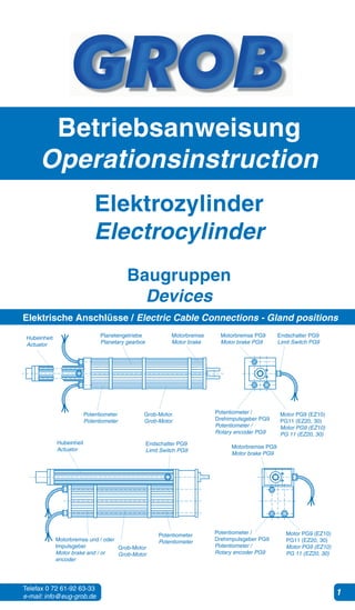
  • 1. Telefax 0 72 61-92 63-33 e-mail: info@eug-grob.de 1 Betriebsanweisung Operationsinstruction Elektrozylinder Electrocylinder Baugruppen Devices Elektrische Anschlüsse / Electric Cable Connections - Gland positions Hubeinheit Actuator Planetengetriebe Planetary gearbox Motorbremse Motor brake Motorbremse PG9 Motor brake PG9 Endschalter PG9 Limit Switch PG9 Potentiometer Potentiometer Grob-Motor Grob-Motor Potentiometer / Drehimpulsgeber PG9 Potentiometer / Rotary encoder PG9 Motor PG9 (EZ10) PG11 (EZ20, 30) Motor PG9 (EZ10) PG 11 (EZ20, 30) Hubeinheit Actuator Endschalter PG9 Limit Switch PG9 Motorbremse PG9 Motor brake PG9 Grob-Motor Grob-Motor Motor PG9 (EZ10) PG11 (EZ20, 30) Motor PG9 (EZ10) PG 11 (EZ20, 30) Potentiometer / Drehimpulsgeber PG9 Potentiometer / Rotary encoder PG9 Potentiometer PotentiometerMotorbremse und / oder Impulsgeber Motor brake and / or encoder
  • 2. Telefax 0 72 61-92 63-33 e-mail: info@eug-grob.de 2 Technische Beschreibung 1.0 Aufbau Höchste Flexibilität bzw. Ausbaufähigkeit und der sich ergebende hohe Nutzwert kennzeichnen die Typenreihe Elektrozylinder. Elektrozylinder ist überwiegend für den industriellen Einsatz konzipiert und deshalb besonders robust und mit hohen Sicherheitsstandards ausgerüstet, sowie in allen Einbaulagen zuverlässig betriebsfähig. Die hohe Wirtschaftlichkeit über alle Optionen wurde durch eine maximale Integration aller Funktionen im Design der Alu-Profile erreicht. Das Hubprofil (Alu-Profil) hat Gebrauchsmusterschutz unter der Nr. 295 05 749.1 1.1 Kolbenrohr Das Kolbenrohr (geschliffen und hartverchromt) ist im Standard gegen Verdrehung gesichert. Die selbstzentrierende Verdrehsicherung vermeidet unter Last unerwünschte innere Radialkräfte. 1.2 Anschlußköpfe Diverse Anschlußköpfe sind ab Lager lieferbar (siehe techn. Ausführungen). 1.3 Spindelarten Sämtliche Antriebe können mit Trapezgewindespindel nach DIN 103, 7e oder mit Kugelgewindespindel ausgeführt werden. Die Ausführung “Trapezgewinde” kann wahlweise mit Bronze- oder Kunststoffspindelmutter geliefert werden. 2.0 Getriebe-Ausführungen Grob-Planetengetriebe 1-, 2- oder 3-stufig (siehe Leistungstabellen) 3.0 Endabschaltung / Positionierung Bei der Endabschaltung bzw. Positionierung sind fol-gende 3 Varianten möglich: 1. elektromechanisch mit zwei von außen verstellbaren Endschaltern Der Hub kann, vom Nennhub ausgehend, um 20 mm vergrößert bzw. um 30 mm verkleinert werden (siehe Einstellanleitung Seite 16) 2. elektromechanisch mit zwei von außen verstellbaren Endschaltern und zwei Sicher- heitsendschaltern (Zwangstrenner). Bewirkt eine längere Baulänge. (Option) Der Hub kann, vom Nennhub ausgehend, um 20mm vergrößert bzw. um 30mm verkleinert werden werden (siehe Einstellanleitung Seite 16) 3. stufenlos-sensorisch mit im Profil des Hubgehäuses integrierten, außenliegend geführten und frei zugänglichen Magnetschaltern (Reedkontakten). (Option) Variante 3 ist selbstverständlich auch mit Variante 1 kombinierbar. 4.0 Motoren Folgende Motoren können verwendet werden: 1. Grob-Drehstrommotor (Standard) 2. Grob-Wechselstrommotor (Option) 3. Gleichstrommotor in Vorzugsspannung 24 Volt (Permanentmagnet) (Option) 4. Servomotorflansch (zum Anbau von Servomotoren) (Option) 5.0 Zuverlässigkeit und Qualitätssicherung Jeder Antrieb wird auftrags- bzw. kundenspezifisch gefertigt und unter “Last” geprüft. Sämtliche Bauteile bzw. Baugruppen unterliegen strengen Kontrollen nach DIN EN ISO 9001 : 2000 und werden (in der Regel bevorratet) aus einer EDV-gesteuerten Lagerhaltung der Endmontage zugeführt. Technical Description 1.0 Design The new Electrocylinder range was developed to offer the designer and user an extremely cost effective, flexible and modular design of actuatorofdurablequalityataneconomicalprice.TheElectrocylinder series, covering thrust forces of 160N up to 40,000N is principally intended for industrial applications. The actuators are therefore of robust construction and designed with a high safety factor, so as to be able to operate reliably in any position. The Electrocylinder range employs special registered design aluminium profiles (ref No 29505749.1) which are an integral part of the function of the electric actuator and it’s drive components. 1.1 Push Rod The push rod (hard chromed and polished) is provided as standard with an anti-rotation guide within the aluminium profile. The self- centring guide prevents radial forces being generated under load and improves the mechanical efficiency. 1.2 End connection and mounting options. Numerous options are available as standard components - refer technical data sheets. 1.3 Spindle types All types can be fittelwith leadt screw to DIN 103, 7e or ball screw. alternatively G9 DIN 286 (130µm/300mm) can be fitted. The standard acme lead screw can be fitted optionally with bronze or plastic nut. 2.0 Gearing Options Grob - Planetary gear box 1/2/3 stage 3.0 Limit switches / Linear positioning For end-of-stroke switching or linear position control there are 3 variants: 1. Two adjustable internal electro-mechanical limit switches. Based on the nominal stroke it’s possible to increase the stroke about 20mm or to reduce it about 30mm (see adjustment instructions page 16). 2. Two adjustable internal electro-mechanical limit switches as well as two fixed position safety limit switches (forcec separators). Results in a longer actuator. (option) Based on the nominal stroke it’s possible to increase the stroke about 20mm or to reduce it about 30mm (see adjustment instructions page 16). 3. Two adjustable proximity switches fitted to an external slideway integrated in the aluminium profile (positioning and safety limit switches). (Option) Variant 3 can be combined with variant 1 of course. 4.0 Electric Motors The following motors are available: 1. Grob three phase motor (Standard) 2. Grob A.C. motor (Option) 3. DC Motor preferred tension 24V (permanent magnet) (Option) 4. Servo motor flange (Attachment for servomotors) (Option) 5.0 Reliability and quality assurance Every drive is manufactured in accordance with the order and customer´ s specifications and is tested under “load”. Our components and subassemblies are subjected to stringent inspections according ISO 9001 and are normally in stock, being taken from a computer-controlled warehouse for final assembly. Refer to the “Individual descriptions” for detailed lists and explanations.
  • 3. Telefax 0 72 61-92 63-33 e-mail: info@eug-grob.de 3 6.0 Bestimmungsgemäße Verwendung Verwenden Sie den Antrieb ausschließlich zum Antreiben von Maschinen, Vorrichtungen und Anlagen, die eine mittelbare oder unmittelbare Gefährdung von Personen ausschließen und bei einer Umgebungstemperatur von 0-60°C. Eine Personenbeförderung ist ohne vorherige Rücksprache mit dem Hersteller (oder der zuständigen Vertretung) nicht zulässig. Ist eine mittel- oder unmittelbare Gefährdung von Personen nicht auszuschließen, müssen zwingend zusätzliche Maßnahmen (Abdeckung, Absperrung, usw.) getroffen werden, die das Risikopotential ent-sprechend minimieren. Verwenden Sie den Antrieb nicht in explosionsgefährdeten Räumen. Stellen Sie sicher, dass der Antrieb nicht überlastet werden kann. 7.0 Empfehlung Durch Verwendung eines gefederter Anschlußkopfes (Option) können Stoßbelastungen gedämpft werden. Generell sollte bei der Festlegung der Antriebsgröße genügend Sicherheit einbezogen werden. 8.0 Optionen Folgende zusätzliche Optionen sind wählbar: 1. Zwei sensorische Betriebsendschalter (Magnetschalter; Reed-Kontakt) mit/ohne zwei zusätzlich 2 Endschalter 2. Befestigungsarten: A/B/C/D (siehe ”Kombinationsmöglichkeiten” S. 18) 3. Anschlußköpfe (siehe ”Kombinationsmöglichkeiten” S. 18) 4. Bremse 5. Verschiedene Versionen Wendelpotentiometer oder Drehimpulsgeber 6. Kolbenrohr aus Edelstahl Nr. 1.4301 DIN 2462 (Nirosta) 7. Flansche zum Anbau der gängigsten Servomotoren 8. Kunststoff-Spindelmutter zur Erzielung von hoher Lebensdauer bei reduzierter Last. 9. Flansche zum Anbau der gängigsten Servomotoren 10. Kunststoff-Spindelmutter zur Erzielung von hoher Lebensdauer bei reduzierter Last. 6.0 Conditions of use It is a condition of sale that MORAT components shall not be used for the movement of loads whereby persons can be directly or indirectly endangered. The application of MORAT linear actuators in equipment which is intended for the transport of passengers is only permissable after prior written consultation and the agreement of the manufacturer MORAT or their represantatives. We would refer users of actuators to safety rules, regulations and laws governing the protection of personnel working in the area of moving equipment and to the need for protective guards or barriers. Similarly-protective measures are required where suspended loads are involved. 7.0 Special protective measures It is possible to bring the linear actuators to a high safety standard by using the following option: 1. elastic connection head (option) (for absorbing shock load) Generally the actuator size chosen should be sufficiently enough. 8.0 Options The following additonal options can be chosen: 1. Two sensoric operating limit switches (solenoid switch; Reed contact) with/without two safety limit switches. 2. Mounting types: A/B/C/D (see system configuration P. 18) 3. Connecting heads (see system configuration P. 18) 4. Bellows 5. Brake 6. Helical potentiometer. (only version A and P), torque counter etc. 7. Increased service life with the same output: Next largest size, or with the same size via output reduction. 8. Piston tube (Stainless steel No. 1.4301 DIN 2462) 9. Servo flange for attachment of most common servomotors. 10. Plastic spindle nut, high service life in case of reduced load. Technische Beschreibung Technical Description Einbau- und Betriebsanleitung Installation & Operation 1.0 Sicherheitshinweise • Lesen Sie vor der Montage bzw. Inbetriebnahme alle Dokumente sorgfältig durch und halten Sie die Anweisungen dieser Einbau- und Betriebsanleitung genau ein. 2.0 Dokumentation Im Katalog sind alle erforderlichen Dokumente enthalten. Sie können jedoch folgende Unterlagen erxtra anfordern: • Elektro-Anschlussplan • Technische Beschreibung 2.1 Kabellänge Die Standard-Kabellänge beträgt 1,5 m. elektrisc 3.0 Aufstellung, Anbau und elektrische Inbetriebnahme 1.0 Attention: All documentation supplied is to be carefully studied before installation and start-up. Installation and electrical connection of the equipment should be made by qualified personnel! Important technical data is given on adhesive foil attached to the actuator. 2.0 Documentation The complete documentation is in the main catalogue Available in doc file is: • Set product discription • Electrical connection diagram 2.1 Connecting cable tails The standard length of cable provided is appr. 1.5 meters. 3.0 Installation and Commissioning
  • 4. Telefax 0 72 61-92 63-33 e-mail: info@eug-grob.de 4 Einbau- und Betriebsanleitung Installation & Operation 3.1 Aufstellung und Anbau Tragen Sie bei Transport und Montage des Antriebes Sicherheitsschuhe. Ein herabfallender Antrieb kann Verletzungen hervorrufen. Montieren Sie den Antrieb ohne Verspannungen. Anbauteile dürfen nicht durch Stöße oder Schläge montiert werden. Die Festigkeitsklasse der Befestigungsschrauben muß min. 8.8 sein. Die verstellbaren Befestigungsarten B und C müs- sen symmetrisch zueinander angeordnet sein. Die Befestigungsschrauben müssen mit dem vorgeschriebenen Anzugsmoment angezogen werden: EZ - Typ 10 = 3Nm, EZ - Typ 20 = 10Nm, EZ - Typ 30 = 25Nm 3.2 Elektrische Inbetriebnahme • Stellen Sie vor der Inbetriebnahme sicher, dass die Stromzufuhr unterbrochen und gegen unbeabsich-tigtes Einschalten gesichert ist. • Schließen Sie den Antrieb nur an ein Netz mit funk- tionierendem Schutzleiter an. • Lesen Sie den Schaltplan sorgfältig durch und achten Sie auf die richtige Betriebsspannung (siehe auch Typenschild auf dem Antrieb) • Alle herausgeführten Kabel sind nach Schaltplan an- zuschließen. Werden Endschalter und/oder Motor- Thermoschutz nicht angeschlossen, kann der Antrieb zerstört werden. Der Thermoschutz soll im Fehlerfall den Antrieb stromlos schalten (Öffner) Achtung! Beim Absinken der Temperatur schaltet der Antrieb selbsttätig wieder ein (Bimetal). • Prüfen Sie durch Tip-Betrieb die Hubrichtung. Um die Hubrichtung umzukehren tauschen Sie zwei Phasen der Netzleitung. • Die Antriebe werden standardmäßig in der Schutzart IP54 ausgeliefert. Die Antriebe der Baureihe Elektrozylinder 10, 20, 30 haben in Sonderausführung zusätzlich Sicherheits- endschalter (Zwangstrenner) nach VDE 0113, welche den Antrieb vor Zerstörung bewahren. Ist der Antrieb auf die Sicherheitsendschalter aufgelaufen, kann die Unterbrechung des Stromkreises durch Drehen der Motorwelle über einen Innensechskant bzw. durch ein Handrad (Option) freigeschalten werden. Ebenfalls kann durch Verstellen der Endschalter in Richtung Hubvergrößerung (s. Einstellanleitung) die Freigabe erfolgen, sofern nicht bereits die max. Hublänge eingestellt ist. (Elastomerdämpfung in den Endlagen bietet zusätzlichen mechanischen Schutz). 4.0 Wichtige Hinweise 4.1 Blockierung des Kolbenrohres Bei häufiger Blockierung des Kolbenrohres durch zu hohe Hubkraft bzw. Auffahren gegen Festanschlag besteht die Gefahr einer Beschädigung des Antriebes! Notpuffer aus Elastomer sind in den Endlagen integriert und nur für den Notfall vorgesehen. 4.2 Besondere Schutzeinrichtungen Durch den Einsatz eines gefederter Anschlußkopf (Option) kann der Antrieb auf einen höheren Sicher-heitsstandard gebracht werden: Generell sollte bei der Festlegung der Antriebsgröße genügend Sicherheit einbezogen werden. 3.1 Notes for the mechanical installation To ensure a trouble free and long working life of the actuator, the following should be noted: The force applied through the thrust tube should be axial to the actuator. If in doubt it is always better to employ rod eye - rod eye, or rod eye - trunnion mounting. The installed position should not be pre-loaded in any way. The piston rod has as standard an internal anti-rotation guide (this can be omitted if preferred). The mounting options B (adjustable Trunnion) and C (adjustable brackets) should be fixed symetrically. The fixing screws are to be tightened to the following torque settings: EZ - Type 10 = 3 Nm EZ - Type 20 = 10Nm EZ - Type 30 = 25Nm 3.2 Notes for Electrical installation The following points are to be noted: All cables from the actuator are to be correctly connected according to the wiring diagrams. The correct matching supply voltage is to be checked. After connection, check that travel direction is correctly signaled by ”jogging”. Should the direction be incorrect the cable connections are to be changed (or current phase). The standard Elektrozylinder are fitted with safety end-switches (current breaker) in accordance with VDE 0113, designed to prevent damage to the equipment. If the linear movement is driven to the safety switch, thereby opening the circuit, an Allen Key socket is provided for turning the motor until this is again closed (there is also a fixed hand-wheel option). The closing can also be effected by adjusting the limit switches into direction of larger stroke if the max. stroke lenght hasn’t been set (additional mechanical protection of final positions by elastomeric damping). 4.0 Safety Measures 4.1 Blocking of thrust tube Elastomer buffers are fitted internally within the actuator to limit damage if the actuator is driven to the mechanical stroke limit. If however, this occurs repeatedly or the actuator is driven to a rgid stop, this can lead to blocking of the screw nut and mechanical damage. 4.2 Conditions of use It is a condition of sale that Grob components shall not be used for the movement of loads whereby persons can be directly or indirectly endangered. The application of Grob linear actuators in equipment which is intended for the transport of passengers is only permissable after prior written consultation and the agreement of the manufacturer Grob or their represantatives. We would refer users of actuators to safety rules, regulations and laws governing the protection of personnel working in the area of moving equipment and to the need for protective guards or barriers. Similarly-protective measures are required where suspended loads are involved.
  • 5. Telefax 0 72 61-92 63-33 e-mail: info@eug-grob.de 5 4.3 Umgebungstemperaturen, Kondenswasser Halten Sie mit dem Hersteller Rücksprache, wenn ein Einsatz unter 0°C vorgesehen ist. Bei Minustemperatur muß mit einem verzögerten Anlaufverhalten gerechnet werden. Im Tieftemperaturbereich müssen grundsätzlich geeignete Anschlußkabel verwendet werden. Bei ständig wechselnden Temperaturen wird die Bildung von Kondenswasser begünstigt. Ebenso bei Einsatz außerhalb von Gebäuden, bzw. bei hoher Luftfeuchtigkeit. Das werksseitige Anbringen von Kondenswasserbohrungen (ø 2 mm) unter Angabe der jeweiligen Einbaulage (in Verbindung mit einer Feuchtschutzlackierung von Rotor und Stator) bewirkt eine deutliche Verbesserung. Achtung! Durch die Kondenswasserbohrung wird die standardmäßige Schutzart (IP54) beeinträchtigt. Eine Dauerbeheizung des Getriebes erfüllt den gleichen Zweck. Beaufschlagen Sie hierzu eine Phase der Netzleitungen mit Strom wenn der Antrieb stillsteht. Das Antrieb bleibt dadurch im Bereich von ca. 30°C. Da je nach Motortyp unterschiedliche Spannungen erforderlich sind, ist unbedingt Rücksprache mit dem Hersteller oder der zuständigen Vertretung zu halten. Bremsen Sie den Antrieb nicht durch Umpolen der Netzleitungen, die Lebensdauer verringert sich sonst erheblich. 5.0 Wartung und Schmierung 5.1 Schmierung von Anschlußkopf und Hubprofil Die Antriebe sind bei Auslieferung mit einer Langzeitschmierung ausgerüstetundbesitzeneinenSchmiernippelamAnschlußkopf. Hier sollte nach ca. 500 Doppelhüben eine Nachschmierung mit ca. 3 bis 6 Gramm Schmierstoff (siehe Schmierstoffangabe) vorgenommen werden.Auch in der Mitte des Hubprofils befindet sich ein Schmiernippel. Dieser sollte ebenfalls nach ca. 5.00 Doppelhüben (bei ausgefahrenem Kolbenrohr) nachgeschmiert werden. Dadurch wird die Lebensdauer wesentlich erhöht. Von Zeit zu Zeit sollte - je nach Einsatzfall - das Kolbenrohr mit einem geölten Tuch gereinigt werden. 5.2 Verschleiß der Spindel Bei festgestelltem Verschleiß der Trapez- oder Kugel- gewindespindel bzw. Spindelmutter empfiehlt sich ein kompletter Austausch im Herstellerwerk. Da diese Teile je nach Belastungsart und Hubgeschwindigkeit einem natürlichen Verschleiß unterliegen, wird empfohlen, frühzeitig einen Ersatzantrieb (Austauschantrieb) beim Herstellerwerk/ Vertretung zu ordern. 5.3 Garantieanspruch und Reparatur Alle Antriebe werden vor der Auslieferung einem eingehenden Probelauf unterzogen und entsprechend den Bestelldaten geprüft und mit dem Zeichen versehen. Während der Garantiezeit darf der Antrieb nicht geöffnet werden. Eine Demontage entbindet den Hersteller von jeglicher Garantieleistung. Im Reparaturfall senden Sie den Antrieb an den Hersteller oder eine geeignete Vertretung zurück. Gegen Berechnung kann vom Hersteller kurzfristig eine Servicekraft zur Verfügung gestellt werden. 6.0 Produktlebensende 6.1 Ist die angegebene Hubzahl erreicht, können Sie den Antrieb zur Überholung zurück zum Hersteller schicken. 6.2 Möchten Sie den Antrieb entsorgen, so achten Sie auf eine umweltgerechte Entsorgung und auf die Einhaltung aller gesetzlichen Vorschriften. 4.3 Special protective measures It is possible to bring the linear actuators to a high safety standard by using the following option: 1. elastic connection head (option) Generally the actuator size chosen should be sufficiently enough. 5.0 Maintenance and Lubrication 5.1 Lubrication of thrust tube and spindle mechanism Actuators are sufficiently lubricated prior to despatch for c.a. 100,000 cycles (referred to base stroke) and have a lubrication nipple at the rod-end. Additional lubrication with c.a. 3-6 grams of approved grease are recommended after appr. 500 full cycles. A secondary lubrication nipple is provided in the centre of the actuator body, this should be replenished every 500 full cycles to achieve maximum working life. From time to time the surface of the thrust tube should be lightly oiled. 5.2 Spindle wear If it is established that the spindle or nut is worm, it is recommended that all wearing parts be replaced. As wear is inevitable, depending on the operating cycle frequency, it is recommended that a replacement actuator is ordered punctually at the manufacturer / representative. 5.3 Guarantees All actuators are carefully checked and tested prior to shipment in accordance with the order specification. All Grob products are provided with a marking. During the guarantee period actuators may only be dismantled with Grob works approval, otherwise invalidating the guarantee. Repairs If repairs are required, we would recommend returning the equipment to Grob GmbH or to one of our service centres. In urgent cases Grob GmbH can provide a service engineer. 6.0 Miscellaneous Actuators are designed to operate in ambient tem-peratures of 0°C to +60°C. Where the ambient temperature is frequently (or permanently) lower than 0°C the operation of the motor will lead to a discernable slower start. Also where frequent temperature extremes occur, there is a risk of condensation build-up in the motor windings and actuator body. We recommend generally a stand-by heating (single phase connection) and where required, special paint finish to rotor and stator. For low temperature use, special cables must be employed. 7.0 Recommended Lubricants The following are used by Grob works: Acme lead screw spindle and nut: Type RENOLIT GLS00 Consistency 00, Basis Polyalphaolefin (Supplier: Fuchs) Ball screw spindle and nut: Type RENOLIT Unitemp 2 Consistency 2, Basis Polyalphaolefin (Supplier: Fuchs) Planetary gear box: Type Renoplex GLP1 Consistency 1 (Supplier: Fuchs) Low temperature application for gear boxes: Type AR4 Consistency 00 For later lubrication, other lubricant makes may be used. For lead or ball screw these should be polyalphaolefin based and of the same consistency. Einbau- und Betriebsanleitung Installation & Operation
  • 6. Telefax 0 72 61-92 63-33 e-mail: info@eug-grob.de 6 Schaltplan für Ausführung Drehstrom Three-phase version Anschlußbeispiel mit Wendeschütz und Bremse Example with reversing contactor and brake Motorkabel Motor cable Der gezeichnete Schaltungsvorschlag ist in Selbsthaltung ausgeführt. Soll der Antrieb im Tippbetrieb betätigt werden, entfallen die beiden Schützkontakte über T1 und T2. The proposed connection incorporates latching. Protective contacts T1 and T2 are dropped in case of inching operation. Standard - Belegung der herausgeführten Anschlüsse aller möglichen Komponenten Standard cable connection for all possible variants Endschalter Limit switches Bremse Ruhestrombet. Brake (Spring Set / Fail Safe brake) Potentiometer Potentiometer Reed-Kontakte (max. 100V ~ / 10VA) Reed switches Elektrozylinder Elektrozylinder Elektrozylinder Elektrozylinder Elektrozylinder Elektrozylinder
  • 7. Telefax 0 72 61-92 63-33 e-mail: info@eug-grob.de 7 Schaltplan für Ausführung Wechselstrom A.C. version Anschlußbeispiel mit Wendeschütz und Bremse Example with reversing contactor and brake Motorkabel Motor cable Standard - Belegung der herausgeführten Anschlüsse aller möglichen Komponenten Standard cable connection for all possible variants Endschalter Limit switches Bremse Ruhestrombet. Brake (Spring Set / Fail Safe brake) Potentiometer Potentiometer Reed-Kontakte (max. 100V ~ / 10VA) Reed switches Anschlußbeispiel mit Schalter Example with switches Elektrozylinder Elektrozylinder Elektrozylinder Elektrozylinder Elektrozylinder Elektrozylinder Elektrozylinder 7 Telefax 0 72 61-92 63-33 e-mail: info@eug-grob.de
  • 8. Telefax 0 72 61-92 63-33 e-mail: info@eug-grob.de 8 Schaltplan für Ausführung Gleichstrom D.C. version Anschlußbeispiel mit Wendeschütz Example with reversing contactor Motorkabel Motor cable Der gezeichnete Schaltungsvorschlag ist in Selbsthaltung ausgeführt. Soll der Antrieb im Tippbetrieb betätigt werden, entfallen die beiden Schützkontakte über T1 und T2. The proposed connection incorporates latching. Protective contacts T1 and T2 are dropped in case of inching operation. Standard - Belegung der herausgeführten Anschlüsse aller möglichen Komponenten Standard cable connection for all possible variants Potentiometer Potentiometer Reed-Kontakte (max. 210V ~ / 10VA) Reed switches Endschalter (max. 16A ~ / 4A=) Limit switches Elektrozylinder Elektrozylinder Elektrozylinder Elektrozylinder Elektrozylinder Elektrozylinder
  • 9. Telefax 0 72 61-92 63-33 e-mail: info@eug-grob.de 9 Einstellanleitung für Endabschaltung / Adjustment Instructions Die Verstellung der Hubposition erfolgt mittels eines Schraubendrehers über die Gewindespindeln 1 und 2 (s. Bild). Spindel 1 ist für die Position ”Hub eingefahren”, Spindel 2 für die Position ”Hub ausgefahren” zuständig. Verstellung der Position ”Hub eingefahren” Stellspindel 1: Drehung links => Hub größer Drehung rechts => Hub kleiner Verstellung der Position ”Hub ausgefahren” Stellspindel 2: Drehung links => Hub kleiner Drehung rechts => Hub größer Die Stellspindel hat eine Steigung von 1mm, was bei einer Umdrehung 1mm Hubweg entspricht. Thje adjustment of the working stroke is made by turning the appropriate screws 1 and 2 with a screw driver (See picture). Screw 1 is destinated for position ”stroke retracted”, screw 2 for position ”stroke extended”. Adjustment of position ”stroke retracted” Adjusting spindle 1: Turning anti-clockwise => increases stroke Turning clockwise => reduces stroke Adjustment of position ”stroke extended” Adjusting spindle 2: Turning anti-clockwise => reduces stroke Turning clockwise => increases stroke The pitch of screw is 1 mm - turning the screw head one full revolution will therefore adjust the stroke switch position by 1 mm. Verstellung mit Schraubendreher Adjustment with screwdriver Position Hub eingefahren Rod retracted Position Hub ausgefahren Rod extended eingefahren retracted ausgefahren extended Telefax 0 72 61-92 63-33 e-mail: info@eug-grob.de 9
  • 10. Telefax 0 72 61-92 63-33 e-mail: info@eug-grob.de 10 Possible positions of push rod => Possible positions of limit switches Hubvariationen bei Standardhublängen Adjustment possibilities with standard stroke lenghts Mögliche Positionen der Hubstange => Mögliche Stellungen der Endschalter