SlideShare ist ein Scribd-Unternehmen logo
1 von 28
Downloaden Sie, um offline zu lesen
Venetian blind drives | Positioning drives
Jalousieantriebe | Stellantriebe
Series D
Baureihe D
DIN EN ISO 9001:2008
DIN EN ISO 14001:2004 + Cor 1:2009
sales@electromate.com
www.electromate.com
ELECTROMATE
Toll Free Phone (877) SERVO98
Toll Free Fax (877) SERV099
www.electromate.com
sales@electromate.com
Sold & Serviced By:
2 | Visit www.dunkermotoren.com for further product information/ Besuchen Sie www.dunkermotoren.de für weitere Produktinformationen
To Our Valued Customers,
Dunkermotoren is a world class leader in high quality motion control solutions to meet
the ever increasing demands for cost effective and reliable drive solutions.
Our comprehensive product range offers the flexibility to provide customized
solutions as well as standardized components.The catalog represents
Dunkermotoren´s years of engineering excellence. The Dunkermotoren Team will
continue to utilize our outstanding engineering and industrial capabilities to meet the
requirements helping you to succeed.
Dunkermotoren
Liebe Kunden,
als führender Hersteller der Antriebstechnik bieten wir Ihnen wirtschaftliche, effiziente
und qualitativ hochwertige Komplettlösungen. Unser umfassendes Produkt- und
Leistungsspektrum ermöglicht Ihnen ein hohes Maß an Flexibilität: Ob standardisierte
Komponenten oder kundenspezifische Anforderungen – bei uns finden Sie bestimmt
die passende Lösung. Mit diesem Katalog können Sie sich einen Überblick über
unsere innovativen und richtungsweisenden Produkte verschaffen.
Das Dunkermotoren-Team berät Sie gerne engagiert und kompetent.
Denn: Ihr Erfolg ist unser Ziel.
Dunkermotoren
sales@electromate.com
www.electromate.com
ELECTROMATE
Toll Free Phone (877) SERVO98
Toll Free Fax (877) SERV099
www.electromate.com
sales@electromate.com
Sold & Serviced By:
Visit www.dunkermotoren.com for further product information/ Besuchen Sie www.dunkermotoren.de für weitere Produktinformationen | 3
Content/ Inhalt
Infos
4 Modular system/ Modulares Baukastensystem
5 Applications/ Anwendungen
16-17 Electrical connections for drives (Venetian-blind and positioning drive)/
Elektrischer Anschluss der Antriebe (Jalousie-und Stellantriebe)
19-23 Setting instructions/ Einstellanweisung
24 Clutches/ Kupplungen
25 Accessories/ Zubehör
Venetianblind&
Positioningdrives/
Jalousie-&
Stellantriebe
6-7 Venetian blind drives/ Jalousieantriebe
8-9 Electronic venetian blind drives/ Elektronische Jalousieantriebe
10-11 SMI technology/ SMI Technologie
12-13 DC drives for interior blinds/ DC-Antriebe innenliegender Sonnenschutz
14-15 Positioning drives/ Stellantriebe
sales@electromate.com
www.electromate.com
ELECTROMATE
Toll Free Phone (877) SERVO98
Toll Free Fax (877) SERV099
www.electromate.com
sales@electromate.com
Sold & Serviced By:
4 | Visit www.dunkermotoren.com for further product information/ Besuchen Sie www.dunkermotoren.de für weitere Produktinformationen
Modular system/ Modulares Baukastensystem
I/O
Condition
m
oni-
toring
Power modul
BG 75 | 500 Watt
Current mode
Motor control
Power modul
BG 95 | 1100 Watt
Power modul
BG 65 | 180 Watt
Power modul
BG 45 | 90 Watt
M
ains
connection
230
VAC
3x400
VAC
Interface for
encoder
Functional safty
STO
SIL
2/3
MI | master
functionality
Speed mode
Position mode Service
interface
µC
Pow
erfactor
com
pensation
6...325
VDC
Flexibility, delivery performance and
complete motion solutions
Standardized motors, gears and modular
accessories are available with a higher
degree of flexibility to address specific
requirements in complete motion solutions.
Flexibilität, Lieferperformance und
umfassende Antriebslösungen
Die Produktpalette von Dunkermotoren ist
so aufgebaut, dass sich mit standardisierten
Motoren und einem modular aufgebauten
Zubehör eine hohe Flexibilität für umfassende
Antriebslösungen ergibt.
Motion control 4.0
»» Motors carry out tasks autonomously
»» Motors monitor their own state and gain 	
	 information from their local environment
»» Motors communicate with other devices 	
	 and with control/ SCADA level
»» Motors adapt flexibly to new tasks
Motion Control 4.0
»» Motoren führen autonom Aufgaben aus
»» Motoren überwachen ihren Zustand und
sammeln Informationen aus der Umgebung
»» Motoren kommunizieren mit anderen
Geräten und mit der Steuerungs bzw.
SCADA Ebene
»» Motoren passen sich flexibel an neue
Aufgaben an
ENCODERS/
GEBER
BRAKES/
BREMSEN
Tacho generators/
Tachogeneratoren
3 -10 V/ 1.000 min-1
Power-on Brakes/
Arbeitsstrombremsen
0.2 - 1 Nm
Power-off Brakes/
Ruhestrombremsen
0.2 - 6 Nm
GEARBOXES/ GETRIEBE
dGo
dMove
dPro	
Incremental Encoder/
Inkrementalgeber
up to 4096 ppr
MOTORS/ MOTOREN
INTEGRATED CONTROLLER/
INTEGRIERTE ELEKTRONIK
Magnetic Pulse
Generators/
Magnetische
Impulsgeber
4 ppr
Permanent Magnet DC-Motors/
Bürstenbehaftete Gleichstrommotoren
3 - 240 Watt
AC-Motors/ Wechselstrom- 
Drehstrommotoren
5 - 100 Watt
Linear Motors/ Linearmotoren
19 - 1860 N
Brushless DC-Servomotors/
Bürstenlose Gleichstrommotoren
6 - 1100 Watt
Worm Gearboxes/ Schneckengetriebe
0.75 - 30 Nm
Planetary Gearboxes/ Planetengetriebe
0.3 - 160 Nm
Spirotec Gearboxes/ Spirotecgetriebe
9 Nm
sales@electromate.com
www.electromate.com
ELECTROMATE
Toll Free Phone (877) SERVO98
Toll Free Fax (877) SERV099
www.electromate.com
sales@electromate.com
Sold  Serviced By:
Visit www.dunkermotoren.com for further product information/ Besuchen Sie www.dunkermotoren.de für weitere Produktinformationen | 5
Some Applications
»» Industrial Automation
»» Robots and Logistics
»» Wood
»» Printing
»» Paper
»» Textile
»» Food  beverage
»» Packaging
»» Semiconductor
»» Material handling
»» Medical devices  laboratory
	equipment
»» Door automation
»» Renewable energies
»» Motive
»» Pumps
»» Sun protection
Beispiele für Anwendungen
»» Industrielle Automatisierung
»» Robotik und Logistik
»» Holzbearbeitung
»» Druckindustrie
»» Papierindustrie
»» Textilmaschinen
»» Lebensmittelmaschinen
»» Verpackungsmaschinen
»» Halbleiterindustrie
»» Materialhandling
»» Medizin- und Labortechnik
»» Türautomation
»» Erneuerbare Energien
»» Motive
»» Pumpen
»» Sonnenschutz
Applications/ Anwendungen
sales@electromate.com
www.electromate.com
ELECTROMATE
Toll Free Phone (877) SERVO98
Toll Free Fax (877) SERV099
www.electromate.com
sales@electromate.com
Sold  Serviced By:
6 | Visit www.dunkermotoren.com for further product information/ Besuchen Sie www.dunkermotoren.de für weitere Produktinformationen
»	 Single-phase capacitor motors for short time 	
	 operation with mounted gear box
»	 Solidly designed and maintenance free for life
»	 With comfortable adjustment of the end
	positions
»	 Single- and double shaft motors are available
»	 With integrated (built in) temperature switch
»	 With integrated electro magnetical brake
»	 With cable 0.5m and mounted connector
»	 Wechselstrom-Induktionsmotoren für
	 Kurzzeitbetrieb mit angebautem Getriebe
»	 Robust und wartungsfrei
»	 Mit Komfort-Endlageneinstellung
»	 End- und Mittelmotoren erhältlich
»	 Mit eingebautem Temperaturwächter
»	 Mit eingebauter elektromagnetischer Bremse
»	 Mit Motorkabel 0,5m und angegossener
	Steckerverbindung
Data/ Technische Daten
Motortype/
Motortyp
D259 / D258 D359 / D358 D839 / D838 D539 D339 120V D839 120V
Operation mode/
Betriebsart
KB 4 Min. KB 4 Min. KB 4 Min. KB 6 Min. KB 4 Min. KB 4 Min.
Input rated voltage/
Anschlussspannung
VAC 230 230 230 230 120 120
Frequenz/
Frequenz
Hz 50 50 50 50 60 60
Rated continuous current/
Nennstromaufnahme
A 0.42 0.58 0.97 0.51 1.21 1.8
Rated input power/
Nennleistungsaufnahme
W 95 132 218 115 132 216
Continuous rated speed/
Nenndrehzahl	
min-1
23 22 23 23 28 28
Continuous rated torque/
Nenndrehmoment	
Nm 2x3 2x5 2x9.5 10 2x4 2x8
Starting torque/
Anlaufmoment	
Nm 2x3 2x5 2x9.5 10 2x4 2x8
Starting input current/
Anlaufstrom
A 0.57 0.7 1.3 0.6 1.5 2.2
Capacitor/
Kondensator
μF 3 4 7 4 14 23
Weight/
Gewicht
kg 1.85 1.94 2.7 1.8 2.0 2.7
Maximum range of revolutions/
Max. Anzahl Umdrehungen
67 67 97 97 97 97
Protection class/
Schutzart
IP 54 54 54 54 54 54
Temperature range/
Temperaturbereich
°C -20 ... +60 -20 ... +60 -20 ... +60 -20 ... +60 -20 ... +60 -20 ... +60
Insulation class/
Isolierstoffklasse
F (155 °C) F (155 °C) F (155 °C) F (155 °C) F (155 °C) F (155 °C)
VDE mark/
VDE Zeichen
VDE EMC mark/
VDE-EMV Zeichen
CE mark/
CE-Zeichen
CCC/
CCC
UL mark/
UL-Zertifizierung
Venetian blind drives/ Jalousieantriebe
»	 D259 | D359 | D339 | D839:
	 adjustable lower and upper end position, additional external limit
	 switch for the upper end position
»	 D258 | D358 | D838:
	 two lower end positions, external limit switch for the upper end postion
»	 D259 | D359 | D339 | D839:
	 untere und obere Endlage einstellbar, zusätzlich Auflaufendschalter
	 für die obere Endlage
»	 D258 | D358 | D838:
	 untere Endlage Doppelendschalter, obere Endlage Auflaufendschalter
»	 D258, D358, D838
Venetian Blind Drives with two lower
end position switches
(Venetian Blind Drives with two lower end
position switches are used in installations with
operating position (interconnection venetian
blinds). The venetian blinds move with slats in
open position down to the first lower end posi-
tion switch (AB1). With an additional move-
down command the venetian blinds move to
the second end position switch (AB2); the slats
close.)
»	 D258, D358, D838
Jalousieantriebe mit zwei unteren End-
schaltern
(Jalousieantriebe mit zwei unteren Endschal-
tern werden bei Anlagen mit Arbeitsstellung
(Verbundjalousien) eingesetzt. Hierbei fahren
die Jalousien in einer geöffneten Stellung der
Lamellen nach unten bis auf den ersten
unteren Endschalter (AB1). Durch einen
weiteren AB-Befehl fahren die Jalousien auf
die zweite untere Endlage (AB2); die Lamellen
werden geschlossen.)
Operating position (slats opened)/
Arbeitsstellung (Lamellen geöffnet)
Closed position/
Schließstellung
Venetian Blind Drives
Jalousieantriebe
• D248, D348, D838
Venetian Blind Drives with two lower
end position switches
(Venetian Blind Drives with two lower
end position switches are used in instal-
lations with operating position (intercon-
nection venetian blinds). The venetian
blinds move with slats in open position
down to the first lower end position
switch (AB1). With an additional move-
down command the venetian blinds
move to the second end position switch
(AB2); the slats close.)
•
J
E
(J
E
A
e
s
L
u
e
d
E
g
AB1
operating position (slats opened)
Arbeitsstellung (Lamellen geöffnet)
AB2
closed position
Schließstellung
Venetian Blind Drives
Jalousieantriebe
• D248, D348, D838
Venetian Blind Drives with two lower
end position switches
(Venetian Blind Drives with two lower
end position switches are used in instal-
lations with operating position (intercon-
nection venetian blinds). The venetian
blinds move with slats in open position
down to the first lower end position
switch (AB1). With an additional move-
down command the venetian blinds
move to the second end position switch
(AB2); the slats close.)
• D248, D348, D83
Jalousieantriebe m
Endschaltern
(Jalousieantriebe m
Endschaltern werd
Arbeitsstellung (Ve
eingesetzt. Hierbei
sien in einer geöffn
Lamellen nach unte
unteren Endschalte
einen weiteren AB
die Jalousien auf d
Endlage (AB2); die
geschlossen.)
AB1
operating position (slats opened)
Arbeitsstellung (Lamellen geöffnet)
AB2
closed position
Schließstellung
D259 | D359
sales@electromate.com
www.electromate.com
ELECTROMATE
Toll Free Phone (877) SERVO98
Toll Free Fax (877) SERV099
www.electromate.com
sales@electromate.com
Sold  Serviced By:
Visit www.dunkermotoren.com for further product information/ Besuchen Sie www.dunkermotoren.de für weitere Produktinformationen | 7
Venetian blind drives/ Jalousieantriebe
D259 | D258 | D359 | D358
7
D249 / D248 / D349 / D348
Maße
D339
(110 )/
D839
(110 V)/
D839
I1
240 275
I2
182 217
I3
152.5 187.5
I4
146.5 181.5
I5
142 177
+ 1.6
- 1
+ 1.5
- 1
+ 1.5
- 0.7
+ 1.2
- 0.5
+ 1.2
- 0.5
Dimensions D539 on request available / Maßbild 539 auf Anfrage erhältlich
D339 (120V) | D839 (120V) | D839
7
D339 (120 V) / D839 (120 V) / D839
D249 / D248 / D349 / D348
Maße
D339
(110 )/
D839
(110 V)/
D839
I1
240 275
I2
182 217
I3
152.5 187.5
I4
146.5 181.5
I5
142 177
+ 1.6
- 1
+ 1.5
- 1
+ 1.5
- 0.7
+ 1.2
- 0.5
+ 1.2
- 0.5
Venetian Blind Drives
Jalousieantriebe
• D248, D348, D838
Venetian Blind Drives with two lower
end position switches
(Venetian Blind Drives with two lower
end position switches are used in instal-
lations with operating position (intercon-
nection venetian blinds). The venetian
blinds move with slats in open position
down to the first lower end position
switch (AB1). With an additional move-
down command the venetian blinds
move to the second end position switch
(AB2); the slats close.)
• D248, D348, D838
Jalousieantriebe mit zwei unteren
Endschaltern
(Jalousieantriebe mit zwei unteren
Endschaltern werden bei Anlagen mit
Arbeitsstellung (Verbundjalousien)
eingesetzt. Hierbei fahren die Jalou-
sien in einer geöffneten Stellung der
Lamellen nach unten bis auf den ersten
unteren Endschalter (AB1). Durch
einen weiteren AB-Befehl fahren
die Jalousien auf die zweite untere
Endlage (AB2); die Lamellen werden
geschlossen.)
AB1
operating position (slats opened)
Arbeitsstellung (Lamellen geöffnet)
AB2
closed position
Schließstellung
Dimensions D539 on request available / Maßbild 539 auf Anfrage erhältlich
Dimensions/
Maße
D339
(110V)
D839
(110V)/
D839
I1
+ 1.6 | - 1 240 275
I2
+ 1.5 | - 1 182 217
I3
+ 1.5 | - 0.7 152.5 187.5
I4
+ 1.2 | - 0.5 146.5 181.5
I5
+ 1.2 | - 0.5 142 177
D539
sales@electromate.com
www.electromate.com
ELECTROMATE
Toll Free Phone (877) SERVO98
Toll Free Fax (877) SERV099
www.electromate.com
sales@electromate.com
Sold  Serviced By:
8 | Visit www.dunkermotoren.com for further product information/ Besuchen Sie www.dunkermotoren.de für weitere Produktinformationen
Expanded capability profile in comparison with traditional
motors based on AC motors with mechanical end limit
switches.
» Slow speed at each start in each direction of rotation enables
	 a sensitive setting of the slat angle thus an optimized controlling
	 of the insolation
» The load-independent speed control keeps the speed constant
	 for the whole height of the blind. As a result of this the view of
	 the running of the blind is consistent
» A new concept of the braking system eliminates disturbing
	 braking noises
» For the comfortable adjustment of the end position it is not
	 necessary to have direct access to the motor by using the
	 manual control device of Dunkermotoren
» Several motors can be connected in parallel
» Storage of the travel command after operation of the up our
	 down button for more than 3 seconds
» Because of the integration of many functions which have been
	 realized in the past with external control devices the motor can
	 be controlled by very easy control devices
Erweitertes Leistungsspektrum gegenüber klassischen
Jalousieantrieben auf Wechselstrombasis mit mechanischen
Endschaltern.
»	 Schleichdrehzahl für ca. 3 Sek. bei jedem Anfahren ermöglicht
	 eine feinfühlige Einstellung des Lamellenwinkels und somit
	 optimale Steuerung der Sonneneinstrahlung
»	 Die lastunabhängige Drehzahlregelung hält die Drehzahl über
	 die gesamte Behanghöhe konstant und führt so zu einem
	 einheitlichen Behanglaufbild insbesondere bei großen Fassaden
	 mit vielen Jalousien
»	 Ein neues Bremskonzept eliminiert störende Bremsgeräusche
»	 Die Einstellung der Endlagen erfolgt komfortabel über ein
	 Steuerkabel, ohne daß der Motor zugänglich sein muß
»	 Mehrere Motoren können über einen Taster parallel geschaltet werden
»	 Speicherung (Selbsthaltung) der Fahrbefehle nach Drücken der
	 Auf- oder Ab-Taste länger als 3 Sekunden
»	 Durch die Intergration vieler Funktionen in den Antrieb, welche
	 bisher in den Motorsteuergeräten enthalten sind, können zur
	 Steuerung des Motors einfachste Steuergeräte verwendet
	werden
Electronic venetian blind drives/ Elektronische Jalousieantriebe
Data/ Technische Daten
Motortype/
Motortyp
D370 / D370 SMI
Input rated voltage/
Anschlussspannung
VAC 230
Frequenz/
Frequenz
Hz 50
Continuous rated torque/
Nenndrehmoment
Nm 2x5*
Slow speed/
Schleichgang
min-1
5
Fast speed/
Schnellgang	
min-1
23
Rated continuous current/
Nennstromaufnahme	
A~ 2x3
Rated input power/
Nennleistungsaufnahme	
W 92
Maximum range of revolutions/
Max. Anzahl Umdrehungen
140
Starting torque/
Anlaufmoment
Nm 2x5
Maximum current/
Maximale Stromaufnahme
A 0.82
Weight/
Gewicht
kg 1.3
Protection class/
Schutzart
IP 54
VDE mark/
VDE Zeichen
VDE EMC mark/
VDE-EMV Zeichen
CE mark/
CE-Zeichen
sales@electromate.com
www.electromate.com
ELECTROMATE
Toll Free Phone (877) SERVO98
Toll Free Fax (877) SERV099
www.electromate.com
sales@electromate.com
Sold  Serviced By:
Visit www.dunkermotoren.com for further product information/ Besuchen Sie www.dunkermotoren.de für weitere Produktinformationen | 9
Electronic venetian blind drives/
Elektronische Jalousieantriebe
D370 | D370 SMI
9
Electronic Venetian Blind Drives
Elektronische Jalousieantriebe
D370 / D370 SMI
D470 / D470 SMI
sales@electromate.com
www.electromate.com
ELECTROMATE
Toll Free Phone (877) SERVO98
Toll Free Fax (877) SERV099
www.electromate.com
sales@electromate.com
Sold  Serviced By:
10 | Visit www.dunkermotoren.com for further product information/ Besuchen Sie www.dunkermotoren.de für weitere Produktinformationen
SMI technology/ SMI-Technik
The SMI interface defines a standard and robust link between
roller shutter/venetian blind drives and control units. Low cost but
effective interface circuits are built into the SMI drive and the
SMI control unit. These match up to the building’s demanding
requirements.
SMI drives have 5-core leads. Three cores are for the power supply
and the earthing (L, N and PE) and two cores are for the data
transfer. The data transfer is so robust that no special types of leads
are required. In addition the power supply and the data transfer
(I+ and I-) can coexist in the same lead.
The data signal leads are protected against any polarity reversal so
that no incorrect connection can destroy a drive. The input circuit is
protected against overvoltage so that no destruction is possible if
high interference voltages occur.
Thanks to the ingenious SMI circuit interface, lead lengths of up
to 350 m can be accommodated. This means there are virtually no
limitations that have to be taken into account during the planning.
Data signal transfers take place at 2,400 bits per second.
Together with the very efficient standard commands this ensures
fast response times.
A parallel connection of up to 16 drives to the same motor control
unit is possible. Thanks to a global addressing it is possible to have
just one start-up in a wired system.
The drives can be addressed together or individually, i.e. the allocation
of one address per drive is possible, but is not necessary if all
the drives are to be controlled together.
For further information please see at
www.standard-motor-interface.com
Die SMI-Schnittstelle definiert eine einheitliche und robuste Verbindung
zwischen Rollladen-/Jalousieantrieben und Steuerungen. Jeweils im
SMI-Antrieb und in der SMI-Steuerung sind kostengünstige, aber
wirkungsvolle Interfaceschaltungen eingebaut, die den anspruchsvollen
Anforderungen im Gebäude entsprechen.
SMI-Antriebe haben Anschlussleitungen mit 5 Adern. Drei Adern sind
für die Stromversorgung und den Schutzleiter (L, N und PE) und zwei
Adern sind für die Datenübertragung. Die Datenübertragung ist so
robust, dass keine speziellen Leitungstypen erforderlich sind. Zudem
können Stromversorgung und Datenübertragung (I+ und I-) in der
gleichen Leitung geführt werden.
Die Telegrammleitungen sind so verpolsicher, dass ein Falschanschluss
keine Zerstörung eines Antriebes zur Folge haben kann. Die Eingangss-
chaltung hat eine so hohe Überspannungsfestigkeit, dass auch bei
hoher Störspannung keine Zerstörung möglich ist.
Dank dem ausgeklügelten SMI-Schaltungsinterface können
Leitungslängen bis zu 350m überbrückt werden. Es sind kaum mehr
Einschränkungen bei der Planung zu berücksichtigen.
Die Telegrammübertragung erfolgt mit 2400 Bit pro Sekunde.
Zusammen mit sehr effizienten Standardbefehlen ist eine hohe
Reaktionsgeschwindigkeit gesichert.
Die Parallelschaltung von bis zu 16 Antrieben an der gleichen
Motorsteuerung ist möglich. Dank einer globalen Adresse ist auch
eine Inbetriebnahme im verdrahteten System möglich.
Die Antriebe können gemeinsam oder einzeln angesprochen werden,
d.h. die Vergabe einer Adresse pro Antrieb ist möglich, ist aber bei
gemeinsamer Ansteuerung nicht notwendig.
Weitere Informationen zur SMI-Technik finden Sie bei
www.standard-motor-interface.com
Venetian blind drives/ Jalousieantriebe
Compatible thanks SMI/ Kompatibel dank SMI
Controls device/
Steuerung
Building management system
SMI drive/ SMI-Antrieb
Controls system/ Steuerung
sales@electromate.com
www.electromate.com
ELECTROMATE
Toll Free Phone (877) SERVO98
Toll Free Fax (877) SERV099
www.electromate.com
sales@electromate.com
Sold  Serviced By:
Visit www.dunkermotoren.com for further product information/ Besuchen Sie www.dunkermotoren.de für weitere Produktinformationen | 11
Selection help for electrical venetian blinds/
Auswahlhilfe für Jalousieantriebe
The parameter diagram is a possibility to identify the maximum
surface for venetian blinds in dependence of width, height of the
blind and torque of the motor.
Furthermore the resulting surfaces are depending on the current
venetian blinds system.
For creating the diagram the following datas are needed:
» Take-up spindle radius of lifting band (mm)
» Lifting band thickness (mm)
» Specific mass of slats (kg/m2)
» Specific mass of bottom rail (kg/m)
» Safety margin of motor torque (%)
» Friction factor (%)
For example:
Take-up spindle radius of lifting band: 10.5 mm
Lifting band thickness: 0.27 mm
Specific mass of slats: 1.53 kg/m2
Specific mass of bottom rail: 0.427 kg/m
Safety margin of motor torque: 10%
Friction factor: 10%
On request, Dunkermotoren provides a specific diagram depending on
the details (as in the example above mentioned datas) of the venetian
blind.
Das Parameter-Diagramm dient zur Ermittlung der maximalen Jalousie-
fläche in Abhängigkeit von Breite und Höhe der Jalousie sowie
vom Motormoment.
Die sich ergebenden Flächen sind darüber hinaus abhängig vom
jeweiligen Jalousie-System.
Zur Erstellung eines Diagrammes benötigen wir folgende Daten:
»	 Wickelkernradius in mm
»	 Zugbanddicke in mm
»	 Gewicht der Lamellen in kg/m2
»	 Gewicht der Unterschiene (Fallstab) in kg/m
»	 Gewünschte Sicherheit des Motormomentes in %
»	 Reibungsverluste in %
Beispiel:
Wickelkernradius: 10,5 mm
Zugbanddicke: 0,27 mm
Gewicht der Lamellen: 1,53 kg/m2
Gewicht der Unterschiene: 0,427 kg/m
Sicherheit des Motormomentes: 10%
Reibungsverlust: 10%
Von Dunkermotoren wird auf Anfrage, abhängig von den Daten (wie im
Beispiel oben genannte Daten) der jeweiligen Jalousie, ein spezifisches
Diagramm erstellt.
Width/ Breite m
Height/Höhem
Drives/ Antriebe
20.07.2015
Kunde
Jalousieart
Wickelkernradius in mm: 10,50 mm
Zugbanddicke in mm: 0,27 mm
Lamellengewicht in kg/qm: 1,58 kg/qm
Unterschienengewicht in kg/m: 0,43 kg/m
Reibungsfaktor in %: 10%
Sicherheitsfaktor in %: 10%
0,00
1,00
2,00
3,00
4,00
5,00
6,00
7,00
0,00 1,00 2,00 3,00 4,00 5,00 6,00 7,00 8,00 9,00 10,00
Höheinm
Breite in m
6Nm 9Nm 10Nm 16Nm 20Nm
1
D838, D839
D839 120V
D370, D539
D339 120V
D258, D259
sales@electromate.com
www.electromate.com
ELECTROMATE
Toll Free Phone (877) SERVO98
Toll Free Fax (877) SERV099
www.electromate.com
sales@electromate.com
Sold  Serviced By:
12 | Visit www.dunkermotoren.com for further product information/ Besuchen Sie www.dunkermotoren.de für weitere Produktinformationen
DC drives for interior blinds/ DC-Antriebe innenliegender Sonnenschutz
DC Drives for interior blinds
The Venetian Blind Drives series DCD22 – based on direct-current
technology - are particularly designed for the use in interior blind
applications.
DCD22-2-G
Double shaft drive with integrated incremental encoder. The signals
can be interpreted by the use of an external controller and used for
end position and velocity control. The upper end position is limited by
an external end switch (pushbutton).
DCD22-2-E
Double shaft drive with integrated controller. The integrated
electronics controls upper / lower end position and velocity.
The drive is connected to the power supply via an up/ down
push-button.
The upper and lower end positions are adjustable; an additional
external end switch is available for the upper end position.
DC-Antriebe innenliegender Sonnenschutz
Die Jalousettenatriebe (Jalousieantriebe) der Baureihe DCD22 sind
speziell für den Einsatz im innenliegenden Sonnenschutz konzipierte
Gleichstromantriebe.
DCD22-2-G
Antrieb für mittigen Einbau mit integriertem Inkrementalgeber. Die Sig-
nale des Inkrementalgebers können durch eine externe Steuerung aus-
gewertet und zur Endlagensteuerung und Drehzahlregelung verwendet
werden. Die obere Endlage ist durch einen Auflaufendschalter begrenzt.
DCD22-2-E
Antrieb für mittigen Einbau mit integrierter Steuerelektronik. Die
integrierte Steuerelektronik steuert die obere und die untere
Endlage und regelt die Drehzahl. Der Antrieb wird über einen
Auf-Ab-Taster mit der Spannungsversorgung verbunden.
Die obere und untere Endlage sind einstellbar; für die obere Endlage
steht zusätzlich ein externer Aufaufendschalter zur Verfügung.
Data/ Technische Daten
Motortype/
Motortyp
DCD22-2-E DCD22-2-G
Input rated voltage/
Anschlussspannung
VDC 24 24
Continuous rated torque/
Nenndrehmoment
Nm 2x0.3 2x0.3
Slow speed/
Schleichgang
min-1
5 5*
Fast speed/
Schnellgang
min-1
32 32*
Rated continuous current/
Nennstromaufnahme	
A 0.32 0.32
Rated input power/
Nennleistungsaufnahme	
W 7.7 7.7
Maximum range of revolutions/
Max. Anzahl Umdrehungen	
400 -*
Starting torque/
Anlaufmoment
Nm 2x0.3 2x0.3
Maximum current/
Maximale Stromaufnahme
A 1.4 1.4
Weight/
Gewicht
kg 0.13 0.13
Protection class/
Schutzart
IP 40 40
*Depends on controller/ Abhängig von Steuerung
sales@electromate.com
www.electromate.com
ELECTROMATE
Toll Free Phone (877) SERVO98
Toll Free Fax (877) SERV099
www.electromate.com
sales@electromate.com
Sold  Serviced By:
Visit www.dunkermotoren.com for further product information/ Besuchen Sie www.dunkermotoren.de für weitere Produktinformationen | 13
DC drives for interior blinds/
DC-Antriebe innenliegender Sonnenschutz
Dimensions in mm/ Maßzeichnung in mm
13
0,4
0,3
0,2
0,1
torque/Drehmoment Nm
25
20
15
10
5
0
0 0,5 1 1,5 2 2,5 3
1,8
1,6
1,4
1,2
1
0,8
0,6
0,4
0,2
0
Ratedspeed/Drehzahlmin-1
Current/StromA
0 0,2 0,4 0,6 0,8
torque/Drehmoment Nm
70
60
50
40
30
20
10
0
Ratedspeed/Drehzahlmin-1
Characteristic diagram / Belastungskennlinien
Dimensions in mm / Maßzeichnung in mm
Rated Speed / Drehzahl
DCD22-2-G
Rated Speed / Drehzahl
DCD22-2-E
Current / Strom
DCD22-2-E
Current / Strom
DCD22-2-G
DC Drives for interior blinds
DC-Antriebe innenliegender Sonnenschutz
torque/Drehmoment Nm
25
20
15
10
5
0
0 0,5 1 1,5 2 2,5 3
1,8
1,6
1,4
1,2
1
0,8
0,6
0,4
0,2
0
Ratedspeed/Drehzahlmin-1
Current/StromA
torque/Drehmoment Nm
25
20
15
10
5
0
0 0,5 1 1,5 2 2,5 3
1,8
1,6
1,4
1,2
1
0,8
0,6
0,4
0,2
0
Ratedspeed/Drehzahlmin-1
Current/StromA
70
60
50
40
30
20
10
0
0 0,2 0,4 0,6 MN
Current/StromA
Ratedspeed/Drehzahlmin-1
Characteristic diagram/ Belastungskennlinien
sales@electromate.com
www.electromate.com
ELECTROMATE
Toll Free Phone (877) SERVO98
Toll Free Fax (877) SERV099
www.electromate.com
sales@electromate.com
Sold  Serviced By:
14 | Visit www.dunkermotoren.com for further product information/ Besuchen Sie www.dunkermotoren.de für weitere Produktinformationen
Positioning drives/ Stellantriebe
Positioning drives are motor-gearbox combinations optimised for
repeated, short, powerful movements, which are used in lifting
tables, solaria, smoke-control shutters, venetian blinds.
» With integral, adjustable cut-offs for two end positions
» With integral temperature monitoring
» With integral electromagnetic brake
» With 0.5m motor lead and moulded connector plug
Stellantriebe sind Motor-Getriebe-Kombinationen optimal für
kurzzeitige und kraftvolle Bewegungen werden u.a. in Hubtischen,
Solarien, Rauchklappen, Rolladen, ... eingesetzt.
»	 Mit eingebauter einstellbarer Abschaltung für zwei Endlagen
»	 Mit eingebautem Temperaturwächter
»	 Mit eingebauter elektromagnetischer Bremse
»	 Mit Motorkabel 0,5m und angegossener Steckerverbindung
Data/ Technische Daten
Motortype/
Motortyp
D544 D554 D594 D654S D714S
Operation mode/
Betriebsart
KB 6 Min. KB 6 Min. KB 6 Min. KB 4 Min. KB 4 Min.
Input rated voltage/
Anschlussspannung
VAC 230 230 230 230 230
Frequency/
Frequenz
Hz 50 50 50 50 50
Continuous rated speed/
Nenndrehzahl
rpm 52 23 11 23 110
Rated continuous current/
Nennstromaufnahme
A 0.51 0.51 0.51 0.91 0.97
Rated input power/
Nennleistungsaufnahme	
W 115 115 115 206 218
Continuous rated torque/
Nenndrehmoment	
Nm 4.4 10 20 19 2x2.4
Maximum radial load/
Max. Radiallast	
N 1200 1200 1200 1200 -
Maximum axial load/
Max. Axiallast
N 400 400 400 400 -
Starting rated torque/
Anlaufdrehmoment
Nm 4.4 10 20 19 2x2.4
Starting input current/
Anlaufstromaufnahme
A 0.6 0.6 0.6 1.3 1.3
Capacitor/
Kondensator
µF 4.0 4.0 4.0 7.0 7.0
Maximum range of revolutions/
Max. Anzahl Umdrehungen
212 97 44 97 585
Weight/
Gewicht
kg ca. 2.2 ca. 2.2 ca. 2.3 ca. 2.8 ca. 2.5
Protection class/
Schutzart
IP 54 54 54 54 54
CE mark/
CE Zeichen
sales@electromate.com
www.electromate.com
ELECTROMATE
Toll Free Phone (877) SERVO98
Toll Free Fax (877) SERV099
www.electromate.com
sales@electromate.com
Sold  Serviced By:
Visit www.dunkermotoren.com for further product information/ Besuchen Sie www.dunkermotoren.de für weitere Produktinformationen | 15
D544 | D554 | D594
17
D544 / D554 / D594
D654S
Maße
D544
D554
D594
I1
219 229.3
I2
165.2 175.5
I3
126 136.5
+ 1.6
- 0.9
+ 1.5
- 1
+ 1.2
- 0.5
D714S
Maße D654s
I1
291.3
I2
208.2
I3
176.5
I4
172
+ 1.6
- 1
+ 1.5
- 1
+ 1.5
- 0.7
+ 1.2
- 0.7
D654S
D714S
17
D544 / D554 / D594
D654S
Maße
D544
D554
D594
I1
219 229.3
I2
165.2 175.5
I3
126 136.5
+ 1.6
- 0.9
+ 1.5
- 1
+ 1.2
- 0.5
D714S
Maße D654s
I1
291.3
I2
208.2
I3
176.5
I4
172
+ 1.6
- 1
+ 1.5
- 1
+ 1.5
- 0.7
+ 1.2
- 0.7
17
D544 / D554 / D594
D654S
Maße
D544
D554
D594
I1
219 229.3
I2
165.2 175.5
I3
126 136.5
+ 1.6
- 0.9
+ 1.5
- 1
+ 1.2
- 0.5
D714S
Maße D654s
I1
291.3
I2
208.2
I3
176.5
I4
172
+ 1.6
- 1
+ 1.5
- 1
+ 1.5
- 0.7
+ 1.2
- 0.7
Positioning drives/ Stellantriebe
Dimensions/
Maße
D544
D554
D594
I1
+ 1.6 | - 0.9 219 229.3
I2
+ 1.5 | - 1 165.2 175.5
I3
+ 1.2 | - 0.5 126 136.5
Dimensions/
Maße
D654s
I1
+ 1.6 | - 1 291.3
I2
+ 1.5 | - 1 208.2
I3
+ 1.2 | - 0.7 176.5
I4
+ 1.2 | - 0.7 172
sales@electromate.com
www.electromate.com
ELECTROMATE
Toll Free Phone (877) SERVO98
Toll Free Fax (877) SERV099
www.electromate.com
sales@electromate.com
Sold  Serviced By:
16 | Visit www.dunkermotoren.com for further product information/ Besuchen Sie www.dunkermotoren.de für weitere Produktinformationen
Electrical connections/ Elektrischer Anschluss
Venetian blind and positioning drives
The single-phase, capacitor motors employed are technically-mature
drives which, among other advantages, can be connected directly to an
electrical mains supply. However, particularly with regard to connect-
ing, there are several points that must be observed to avoid the drive
malfunctioning.
» For parallel drives incorporating a pair of drives, a two-pole switch 	
	 must always be used and the connection made as shown in Figure 2
» Direct switching to reverse the direction of rotation should be avoided.	
	 Either a switch with a defined “neutral” position or one with a built-in 	
	 switching delay should be employed. Recommended delay time when 	
	 changing the direction of rotation: at least 200 milliseconds
» Simultaneous up and down commands are not admissible. Only 	
	 mechanically or electrically interlocked switches may be used
» Connection may only be carried out by an authorised electrician
» Installation must be carried out in accordance with the current VDE 	
	 regulations or national regulations specific to the country in 		
	 which it is located!
» The installation must include complete separation of all motor poles 	
	 from the mains supply, or a two-pole switch with contacts which open
	 at least 3 mm may be employed
» A damaged connecting cable has to be replaced by the manufacturer,
	 its service representative or similarly qualified person
Jalousie- und Stellantriebe
Die verwendeten Einphasen-Kondensator-Motoren sind technisch
ausgereifte Antriebe welche u.a. den Vorteil der direkten Anschlußmögli-
chkeit an das elektrische Netz bieten. Jedoch sind gerade beim An-
schluß einige Hinweise zu beachten, um eine Fehlfunktion der Antriebe
auszuschließen.
»	 Bei Parallel-Betrieb zweier Antriebe ist grundsätzlich ein zweipoliger 	
	 Schalter zu verwenden und der Anschluß entsprechend Bild 2
	vorzunehmen
»	 Ein direktes Umschalten der Laufrichtung ist zu vermeiden. Es sind 	
	 entweder Schalter mit einer ausgeprägten „Null“- Stellung oder mit
	 integrierter Umschaltverzögerung zu verwenden. Empfohlene
	 Pausenzeit bei Drehrichtungswechsel: mind. 200 mSek
»	 Gleichzeitige Auf- und Ab-Befehle sind unzulässig Es dürfen nur
	 mechanisch oder elektrisch verriegelte Schalter verwendet werden
»	 Der Anschluß darf nur von einem konzessionierten Elektriker
	 vorgenommen werden
»	 Für die Installation sind die gültigen VDE bzw.länderspezifischen 	
	 Vorschriften zu beachten!
»	 Bei der Installation muß eine allpolige Trennung des Motors vom Netz 	
	 geschaffen werden, oder ein zweipoliger Schalter mit mindestens
	 3 mm Kontaktöffnungsweite verwendet werden
»	 Eine beschädigte Anschlussleitung ist nur zu ersetzen durch den 	
	 Hersteller, seinen Kundendienstvertreter oder einer ähnlich
	 qualifizierten Person
Figure 1:
Connection of a
positioning drive
using a single-pole
switch.
Bild 1:
Anschluss von
einem Stellantrieb
über einen einpoli-
gen Schalter.
D539 | D239 | D339 | D839 | D259 | D544 | D554 | D594 | D654s
D258 | D358 | D838
d positioning drives
motors employed
which, among
nnected directly to
owever, particularly
here are several
d to avoid the drive
ating a pair of drives,
ways be used and
hown in Figure 2
e the direction of
d. Either a switch
osition or one with a
ould be employed.
when changing the
st 200 milliseconds
n commands are
hanically or
tches may be used
arried out by an
d out in accordance
lations or national
country in which it is
de complete
es from the mains
ch with contacts
may be employed
ble has to be
Jalousie- und Stellantriebe
Die verwendeten Einphasen-Kondensator-
Motoren sind technisch ausgereifte Antriebe
welche u.a. den Vorteil der direkten Anschluß-
möglichkeit an das elektrische Netz bieten.
Jedoch sind gerade beim Anschluß einige
Hinweise zu beachten, um eine Fehlfunktion der
Antriebe auszuschließen.
• Bei Parallel-Betrieb zweier Antriebe ist
grundsätzlich ein zweipoliger Schalter zu
verwenden und der Anschluß entsprechend
Bild 2 vorzunehmen
• Ein direktes Umschalten der Laufrichtung ist
zu vermeiden. Es sind entweder Schalter mit
einer ausgeprägten „Null“- Stellung oder mit
integrierter Umschaltverzögerung zu ver-
wenden.
Empfohlene Pausenzeit bei Drehrichtungs-
wechsel: mind. 200 mSek
• Gleichzeitige Auf- und Ab-Befehle sind
unzulässig Es dürfen nur mechanisch oder
elektrisch verriegelte Schalter verwendet
werden
• Der Anschluß darf nur von einem
konzessionierten Elektriker vorgenommen
werden
• Für die Installation sind die gültigen VDE-
bzw. länderspezifischen Vorschriften zu
beachten!
• Bei der Installation muß eine allpolige
Trennung des Motors vom Netz geschaffen
werden, oder ein zweipoliger Schalter mit
mindestens 3 mm Kontaktöffnungsweite
verwendet werden
• Eine beschädigte Anschlussleitung ist nur zu
connections for drives
Elektrischer Anschluss der Antriebe
Figure 1:
Connection of a
positioning drive using
a single-pole switch.
Bild 1:
Anschluß von
einem Stellantrieb
über einen einpoligen
Schalter.
Figure 2:
Connection of
two positioning
drives using a
two-pole switch.
Bild 2:
Anschluß von zwei
Stellantrieben über
einen zweipoligen
Schalter.
Figure 3:
Inadmissible
connection of two
D539/D239/D339/D839/D249/D544/
D554/D594/D654s
D539/D239/D339/D839/D249/D544/
D554/D594/D654s
d positioning drives
otors employed
which, among
nected directly to
wever, particularly
ere are several
to avoid the drive
ting a pair of drives,
ays be used and
own in Figure 2
the direction of
Either a switch
sition or one with a
uld be employed.
when changing the
t 200 milliseconds
commands are
anically or
ches may be used
rried out by an
out in accordance
tions or national
ountry in which it is
e complete
s from the mains
h with contacts
may be employed
Jalousie- und Stellantriebe
Die verwendeten Einphasen-Kondensator-
Motoren sind technisch ausgereifte Antriebe
welche u.a. den Vorteil der direkten Anschluß-
möglichkeit an das elektrische Netz bieten.
Jedoch sind gerade beim Anschluß einige
Hinweise zu beachten, um eine Fehlfunktion der
Antriebe auszuschließen.
• Bei Parallel-Betrieb zweier Antriebe ist
grundsätzlich ein zweipoliger Schalter zu
verwenden und der Anschluß entsprechend
Bild 2 vorzunehmen
• Ein direktes Umschalten der Laufrichtung ist
zu vermeiden. Es sind entweder Schalter mit
einer ausgeprägten „Null“- Stellung oder mit
integrierter Umschaltverzögerung zu ver-
wenden.
Empfohlene Pausenzeit bei Drehrichtungs-
wechsel: mind. 200 mSek
• Gleichzeitige Auf- und Ab-Befehle sind
unzulässig Es dürfen nur mechanisch oder
elektrisch verriegelte Schalter verwendet
werden
• Der Anschluß darf nur von einem
konzessionierten Elektriker vorgenommen
werden
• Für die Installation sind die gültigen VDE-
bzw. länderspezifischen Vorschriften zu
beachten!
• Bei der Installation muß eine allpolige
Trennung des Motors vom Netz geschaffen
werden, oder ein zweipoliger Schalter mit
mindestens 3 mm Kontaktöffnungsweite
verwendet werden
onnections for drives
Elektrischer Anschluss der Antriebe
Figure 1:
Connection of a
positioning drive using
a single-pole switch.
Bild 1:
Anschluß von
einem Stellantrieb
über einen einpoligen
Schalter.
Figure 2:
Connection of
two positioning
drives using a
two-pole switch.
Bild 2:
Anschluß von zwei
Stellantrieben über
einen zweipoligen
Schalter.
Figure 3:
Inadmissible
D539/D239/D339/D839/D249/D544/
D554/D594/D654s
D539/D239/D339/D839/D249/D544/
D554/D594/D654s
Figure 2:
Connection of two
positioning drives
using a two-pole
switch.
Bild 2:
Anschluss von zwei
Stellantrieben über
einen zweipoligen
Schalter.
18
The single-phase, capacitor motors employed
are technically-mature drives which, among
other advantages, can be connected directly to
an electrical mains supply. However, particularly
with regard to connecting, there are several
points that must be observed to avoid the drive
malfunctioning.
• For parallel drives incorporating a pair of drives,
a two-pole switch must always be used and
the connection made as shown in Figure 2
• Direct switching to reverse the direction of
rotation should be avoided. Either a switch
with a defined “neutral” position or one with a
built-in switching delay should be employed.
Recommended delay time when changing the
direction of rotation: at least 200 milliseconds
• Simultaneous up and down commands are
not admissible. Only mechanically or
electrically interlocked switches may be used
• Connection may only be carried out by an
authorised electrician
• Installation must be carried out in accordance
with the current VDE regulations or national
regulations specific to the country in which it is
located!
• The installation must include complete
separation of all motor poles from the mains
supply, or a two-pole switch with contacts
which open at least 3 mm may be employed
• A damaged connecting cable has to be
replaced by the manufacturer, its
service representative or similarly qualified
person
Die verwendeten Einphasen
Motoren sind technisch aus
welche u.a. den Vorteil der d
möglichkeit an das elektrisc
Jedoch sind gerade beim An
Hinweise zu beachten, um e
Antriebe auszuschließen.
• Bei Parallel-Betrieb zweie
grundsätzlich ein zweipoli
verwenden und der Ansc
Bild 2 vorzunehmen
• Ein direktes Umschalten d
zu vermeiden. Es sind en
einer ausgeprägten „Null“
integrierter Umschaltverz
wenden.
Empfohlene Pausenzeit b
wechsel: mind. 200 mSek
• Gleichzeitige Auf- und Ab
unzulässig Es dürfen nur
elektrisch verriegelte Sch
werden
• Der Anschluß darf nur von
konzessionierten Elektrike
werden
• Für die Installation sind di
bzw. länderspezifischen V
beachten!
• Bei der Installation muß e
Trennung des Motors vom
werden, oder ein zweipol
mindestens 3 mm Kontak
verwendet werden
• Eine beschädigte Anschlu
ersetzen durch den Herst
Kundendienstvertreter od
qualifizierten Person
Figure 1:
Connection of a
positioning drive using
a single-pole switch.
Bild 1:
Anschluß von
einem Stellantrieb
über einen einpoligen
Schalter.
Figure 2:
Connection of
two positioning
drives using a
two-pole switch.
Bild 2:
Anschluß von zwei
Stellantrieben über
einen zweipoligen
Schalter.
Figure 3:
Inadmissible
connection of two
positioning drives
using a single-pole
switch.
Bild 3:
Unzulässiger
Anschluss von zwei
Stellantrieben über
einen einpoligen
Schalter
D539/D239/D339/D839/D249/D544/
D554/D594/D654s
D539/D239/D339/D839/D249/D544/
D554/D594/D654s
D539/D239/D339/D839/D249/D544/
D554/D594/D654s
D248/D348/D839
Figure 3:
Inadmissible
connection of two
positioning drives
using a single-pole
switch.
Bild 3:
Unzulässiger
Anschluss von zwei
Stellantrieben über
einen einpoligen
Schalter.
D539 | D239 | D339 | D839 | D259 | D544 | D554 | D594 | D654s
sales@electromate.com
www.electromate.com
ELECTROMATE
Toll Free Phone (877) SERVO98
Toll Free Fax (877) SERV099
www.electromate.com
sales@electromate.com
Sold  Serviced By:
Visit www.dunkermotoren.com for further product information/ Besuchen Sie www.dunkermotoren.de für weitere Produktinformationen | 17
Electronic venetian blind drives
D370 | D370 SMI
» Installation must be carried out in accordance with the current
	 VDE regulations or national regulations specific to the country in
	 which it is located!
» Connection may only be carried out by an authorised electrician
» The installation must include complete separation of all motor poles
	 from the mains supply, or a two-pole switch with contacts which open 	
	 at least 3 mm may be employed
» Operation using a controller with “active path control” by monitoring 	
	 the current draw is not possible, because the current does not pass
	 through the UP and DOWN lines, but through terminal 3 (L1)
» A damaged connecting cable has to be replaced by the manufacturer,	
	 its service representative or similarly qualified person
Elektronische Jalousieantriebe
D370 | D370 SMI
»	 Für die Installation sind die gültigen VDE- bzw. länderspezifischen 	
	 Vorschriften zu beachten!
»	 Der Anschluß darf nur von einem konzessionierten Elektriker 	
	 vorgenommen werden
»	 Bei der Installation muß eine allpolige Trennung des Motors vom Netz 	
	 geschaffen werden, oder ein zweipoliger Schalter mit mindestens
	 3 mm Kontaktöffnungsweite verwendet werden
»	 Eine Bedienung über Ansteuergeräte mit einer „aktiven Wegmessung“
	 mittels Überwachung der Stromaufnahme ist nicht möglich, da die
	 Stromaufnahme nicht über die AUF- oder AB-Leitung sondern über
	 Klemme 3 (L1) erfolgt
»	 Eine beschädigte Anschlussleitung ist nur zu ersetzen durch den
	 Hersteller, seinen Kundendienstvertreter oder einer ähnlich
	 qualifizierten Person
Single operation/ Einzelbetrieb
an-blind drives
/ D470/ D470 SMI
d out in accordance
ulations or national
country in which it
carried out by an
ude complete
les from the
le switch with
ast 3 mm may be
er with
monitoring the
ble, because the
ough the UP and
terminal 3 (L1)
able has to be
urer, its
similarly qualified
Elektronische Jalousieantriebe
D370/ D370 SMI / D470/ D470 SMI
• Für die Installation sind die gültigen VDE- bzw.
länderspezifischen Vorschriften zu beachten!
• Der Anschluß darf nur von einem
konzessionierten Elektriker vorgenommen
werden
• Bei der Installation muß eine allpolige
Trennung des Motors vom Netz geschaffen
werden, oder ein zweipoliger Schalter mit
mindestens 3 mm Kontaktöffnungsweite
verwendet werden
• Eine Bedienung über Ansteuergeräte
mit einer „aktiven Wegmessung“
mittels Überwachung der Stromaufnahme ist
nicht möglich, da die Stromaufnahme nicht
über die AUF- oder AB-Leitung sondern über
Klemme 3 (L1) erfolgt
• Eine beschädigte Anschlussleitung ist nur zu
ersetzen durch den Hersteller, seinen
Kundendienstvertreter oder einer ähnlich
qualifizierten Person
connections for drives
Elektrischer Anschluss der Antriebe
Single operation / Einzelbetrieb
up
down
StAS 4
StAK 4
betrieb No earth connection
required because of
protection class II.
Parallel operation/ Parallelbetrieb
No earth connection required because of protection class II./
Kein Erdungsanschluss am Motor erforderlich, da der Motor die Schutzklasse II erfüllt.
Tomoredrives/
zuweiterenAntrieben
19
Electronic venetian-blind drives
D370/ D370 SMI / D470/ D470 SMI
• Installation must be carried out in accordance
with the current VDE regulations or national
regulations specific to the country in which it
is located!
• Connection may only be carried out by an
authorised electrician
• The installation must include complete
separation of all motor poles from the
mains supply, or a two-pole switch with
contacts which open at least 3 mm may be
employed
• Operation using a controller with
“active path control” by monitoring the
current draw is not possible, because the
current does not pass through the UP and
DOWN lines, but through terminal 3 (L1)
• A damaged connecting cable has to be
replaced by the manufacturer, its
service representative or similarly qualified
person
Elektronische Jalousieantriebe
D370/ D370 SMI / D470/ D470 SMI
• Für die Installation sind die gültigen VDE- bzw.
länderspezifischen Vorschriften zu beachten!
• Der Anschluß darf nur von einem
konzessionierten Elektriker vorgenommen
werden
• Bei der Installation muß eine allpolige
Trennung des Motors vom Netz geschaffen
werden, oder ein zweipoliger Schalter mit
mindestens 3 mm Kontaktöffnungsweite
verwendet werden
• Eine Bedienung über Ansteuergeräte
mit einer „aktiven Wegmessung“
mittels Überwachung der Stromaufnahme ist
nicht möglich, da die Stromaufnahme nicht
über die AUF- oder AB-Leitung sondern über
Klemme 3 (L1) erfolgt
• Eine beschädigte Anschlussleitung ist nur zu
ersetzen durch den Hersteller, seinen
Kundendienstvertreter oder einer ähnlich
qualifizierten Person
Electrical connections for drives
Elektrischer Anschluss der Antriebe
Single operation / Einzelbetrieb
up
down
StAS 4
StAK 4
Parallel operation / Parallelbetrieb
StAS 4
StAK 4
StAS 4
StAK 4
up
down
No earth connection
required because of
protection class II.
Kein Erdungsanschluss
am Motor erforderlich,
da der Motor die
Schutzklasse II erfüllt.
tomoredrives
zuweiterenAntrieben
Electrical connections/ Elektrischer Anschluss
sales@electromate.com
www.electromate.com
ELECTROMATE
Toll Free Phone (877) SERVO98
Toll Free Fax (877) SERV099
www.electromate.com
sales@electromate.com
Sold  Serviced By:
18 | Visit www.dunkermotoren.com for further product information/ Besuchen Sie www.dunkermotoren.de für weitere Produktinformationen
Notes/ Notizen
sales@electromate.com
www.electromate.com
ELECTROMATE
Toll Free Phone (877) SERVO98
Toll Free Fax (877) SERV099
www.electromate.com
sales@electromate.com
Sold  Serviced By:
Visit www.dunkermotoren.com for further product information/ Besuchen Sie www.dunkermotoren.de für weitere Produktinformationen | 19
Venetian blind drives
D539 | D259 | D359 | D839 | D339
The lower end position has already been set in the factory. In general, an
adjustment of the lower end position is not necessary by installation in
the lowered venetian blind.
1. Setting the upper end position (U.e.)
» Drive the blind to at least 0.5 m* below the desired upper end position
» Switch on the venetian blind in the “up” direction and at the same 	
	 time push the adjustment button 1 (Up) for the time the venetian blind 	
	 moved approx. 0.5 m* (about 10 sec.). After this time the adjustment 	
	 button remains snapped in
» Continue to run the venetian blind in the desired end position. A fine 	
	 adjustment is possible by typing on the switch
» To fix the adjustment move in the down direction; the adjustment
	 button snaps out
2. Setting the lower end position (L.e.)
» Drive the blind to at least 0.5 m* above the desired lower end position
» Switch on the venetian blind in the “down” direction and at the same 	
	 time push the adjustment button 2 for the time the venetian blind 	
	 moved approx. 0.5 m* (about 10 sec.). After this time the adjustment 	
	 button remains snapped in
» Continue to run the venetian blind in the desired end position.
	 A fine adjustment is possible by typing on the switch
» To fix the adjustment move in the up direction; the adjustment button 	
	 snaps out
* By venetian blind lengths more than 1.5 m add approx. 0.2 m per meter
Modification of an adjusted end position
Run the venetian blind at a sufficient distance (min. 0.5 m) in direction to
the new end position. Set new position according to item 1 or 2.
Demounting the push button
a) lift one of the side snap locks with a thin screw driver.
b) press the push button to the side. Do not remove the cover below the	
	 push button!
Left side installation of single output shaft motors
The standard version of the single output shaft units is planned for
installation in the right side. In case the unit should be installed in the left
side, the left side version has to be ordered!
Jalousieantriebe
D539 | D259 | D359 | D839 | D339
Die Antriebe sind bei Auslieferung auf die untere Endlage eingestellt. Bei
Einbau in die herabgelassene Jalousie ist eine Einstellung der unteren
Endlage in der Regel nicht erforderlich.
1. Einstellung der oberen Endlage
»	 Jalousie mindestens 0,5 m* unter die gewünschte obere
	 Endlage fahren
»	 Jalousie in „AUF“-Richtung über Taster fahren, hierbei Einstellknopf 1 	
	 für einen Jalausielaufweg von ca. 0,5 m* (ca. 10 Sek.) gedrückt 	
	 halten, danach selbsthaltend
»	 Jalousie weiter in „AUF“- Richtung in die gewünschte Endlage fahren, 	
	 Feineinstellung durch Tippen am Taster möglich
»	 Mit „AB“- Befehl Endlageneinstellung fixieren
2. Einstellung der unteren Endlage
»	 Jalousie mindestens 0,5 m* über die gewünschte untere
	 Endlage fahren
»	 Jalousie in „AB“-Richtung über Taster fahren, hierbei Einstellknopf 2 	
	 für einen Jalousielaufweg von ca. 0,5 m* (ca. 10 Sek.) gedrückt 	
	 halten, danach selbsthaltend
»	 Jalousie weiter in „AB“- Richtung in die gewünschte Endlage fahren, 	
	 Feineinstellung durch Tippen am Taster möglich
»	 Mit „AUF“- Befehl Endlageneinstellung fixieren
* Bei Jalousiehöhen über 1,5 m sind pro zusätzlichem Meter ca. 0,2 m
hinzuzurechnen
Veränderung einer eingestellten Endlage
Jalousie in einen ausreichenden Abstand (mind. 0,5 m) vor die neue
Endlage fahren. Neue Einstellung entsprechend Punkt 1 oder 2
vornehmen.
Demontage des Abschaltpilzes
a) Mit dünnem Schraubendreher einen der seitlichen Schnappver-
	 schlüsse anheben.
b) Schaltpilz seitlich wegdrücken. Die Abdeckung unter dem Schaltpilz 	
	 nicht entfernen!
Linkseinbau von Endmotoren
Standardmäßig sind Endmotoren für den Rechtseinbau vorgesehen.
Bei Linkseinbau ist die Ausführung „Linkslauf“ zu bestellen!
Setting instructions/ Einstellanweisung
ADJUST BUTTONS/ EINSTELLKNÖFPE
» UP | Button 1/ AUF | Einstellknopf 1
» DOWN | Button 2/ AB | Einstellknopf 2
Adjustable end position range:
97 revolutions at the drive Dx39
67 revolutions at the drive Dx49
Einstellbarer Endlagenbereich:
87 Umdrehungen am Abtrieb bei Dx39
67 Umdrehungen am Abtrieb bei Dx49
21
Venetian blind drives
D539/D239/D339/D839/D249
The lower end position has already been set in the factory.
In general, an adjustment of the lower end position is not
necessary by installation in the lowered venetian blind.
1. Setting the upper end position (U.e.)
• Drive the blind to at least 0.5 m* below the desired
upper end position
• Switch on the venetian blind in the “up” direction and at the
same time push the adjustment button 1 (Up) for the time
the venetian blind moved approx. 0.5 m* (about 10 sec.).
After this time the adjustment button remains snapped in
• Continue to run the venetian blind in the desired end
position. A fine adjustment is possible by typing on the
switch
• To fix the adjustment move in the down direction; the
adjustment button snaps out
2. Setting the lower end position (L.e.)
• Drive the blind to at least 0.5 m* above the desired lower
end position
• Switch on the venetian blind in the “down” direction and at
the same time push the adjustment button 2 for the time
the venetian blind moved approx. 0.5 m* (about 10 sec.).
After this time the adjustment button remains snapped in
• Continue to run the venetian blind in the desired end position.
A fine adjustment is possible by typing on the switch
• To fix the adjustment move in the up direction; the
adjustment button snaps out
* By venetian blind lengths more than 1.5 m add approx. 0.2 m per meter
Modification of an adjusted end position
Run the venetian blind at a sufficient distance (min. 0.5 m) in
direction to the new end position. Set new position according
to item 1 or 2.
Demounting the push button
a) lift one of the side snap locks with a thin screw driver.
b) press the push button to the side. Do not remove the cover
below the push button!
Left side installation of single output shaft motors
The standard version of the single output shaft units is planned for
installation in the right side. In case the unit should be installed in
the left side, the left side version has to be ordered!
Jalousieantriebe
D539/D239/D339/D839/D249
Die Antriebe sind bei Auslieferung auf die untere Endlage
eingestellt. Bei Einbau in die herabgelassene Jalousie ist eine Ein-
stellung der unteren Endlage in der Regel nicht erforderlich.
1. Einstellung der oberen Endlage
• Jalousie mindestens 0,5 m* unter die gewünschte obere
Endlage fahren
• Jalousie in „AUF“-Richtung über Taster fahren, hierbei
Einstellknopf 1 für einen Jalausielaufweg von ca. 0,5 m*
(ca. 10 Sek.) gedrückt halten, danach selbsthaltend
• Jalousie weiter in „AUF“- Richtung in die gewünschte
Endlage fahren, Feineinstellung durch Tippen am Taster möglich
• Mit „AB“- Befehl Endlageneinstellung fixieren
2. Einstellung der unteren Endlage
• Jalousie mindestens 0,5 m* über die gewünschte untere
Endlage fahren
• Jalousie in „AB“-Richtung über Taster fahren, hierbei
Einstellknopf 2 für einen Jalousielaufweg von ca. 0,5 m*
(ca. 10 Sek.) gedrückt halten, danach selbsthaltend
• Jalousie weiter in „AB“- Richtung in die gewünschte Endlage
fahren, Feineinstellung durch Tippen am Taster möglich
• Mit „AUF“- Befehl Endlageneinstellung fixieren
* Bei Jalousiehöhen über 1,5 m sind pro zusätzlichem Meter ca. 0,2 m
hinzuzurechnen
Veränderung einer eingestellten Endlage
Jalousie in einen ausreichenden Abstand (mind. 0,5 m) vor die neue
Endlage fahren. Neue Einstellung entsprechend Punkt 1 oder 2
vornehmen.
Demontage des Abschaltpilzes
a) Mit dünnem Schraubendreher einen der seitlichen
Schnappverschlüsse anheben.
b) Schaltpilz seitlich wegdrücken. Die Abdeckung unter
dem Schaltpilz nicht entfernen!
Linkseinbau von Endmotoren
Standardmäßig sind Endmotoren für den Rechtseinbau vorgesehen.
Bei Linkseinbau ist die Ausführung „Linkslauf“ zu bestellen!
Setting instructions
Einstellanweisung
»UP« Button 1 / »Auf« Einstellknopf 1
»DOWN« Button 2 / »Ab« Einstellknopf 2
Adjustable end position range:
97 revolutions at the drive D x39;
67 revolutions at the drive D x49
Einstellbarer Endlagenbereich:
97 Umdrehungen am Abtrieb bei D x39;
67 Umdrehungen am Abtrieb bei D x49
ADJUSt BUttONS / EINStELLKNöpFE
sales@electromate.com
www.electromate.com
ELECTROMATE
Toll Free Phone (877) SERVO98
Toll Free Fax (877) SERV099
www.electromate.com
sales@electromate.com
Sold  Serviced By:
20 | Visit www.dunkermotoren.com for further product information/ Besuchen Sie www.dunkermotoren.de für weitere Produktinformationen
Setting instructions/ Einstellanweisung
Electronic venetian blind drives
D370 | D370 SMI
1. Initial Commissioning
On delivery, the drive is in delivery condition: the position of the drive
corresponds to the lower stop position.
Fit the drive in the lowered venetian blind.
Establish power supply. The drive can only be operated in the up
direction. The up command initiates the position-learning run; the drive
confirms the correct position-learning run by a short stop after 1 sec.
Following change-over to fast speed, the drive travels in lock command
mode to the external limit switch (push button), whereby this position
is stored as the upper end position. After this position-learning run, the
upper end position (corresponds to the push button) and the lower stop
position are set. Further adjustments are only necessary if different up-
per or lower end positions are required (see points 2 and 3).
Note on programming: the drive indicates the duration of pushing the
programming button by means of a short run both in up and down
direction after 2 sec. respectively 5 sec.
2. Setting of the upper end position
Run the drive at least 10cm below the desired upper end position.
Press the programming button for 2 to 5 sec.; after 2 sec. the drive
carries out a short run in up and down direction. Run with the up button
(dead man’s mode) to the required upper end position. The drive con-
firms the correct programming mode by means of a short stop
after a run lasting 1 sec. When the required upper end position is
reached, the position is stored by means of the down button: press
the down button until the drive confirms the correct storage of the end
position by a short stop after a run lasting 1 sec.
3. Setting of the lower end position
Run the drive at minimum 10cm above the desired lower end position.
Press the programming button for 2 to 5 sec.; after 2 sec. the drive
carries out a short run in up and down direction. Run with the down
button (dead man’s mode) to the required lower end position. The drive
confirms the correct programming mode by means of a short stop after
a run lasting 1 sec. When the required lower end position is reached, the
position is stored by means of the up button: press the up button until
the drive confirms the correct storage of the stop position by a short
stop after a run lasting 1 sec.
4. Re-establishing the delivery state
Press the programming button for 5 to 10 sec.; after 2 sec. respectively
5 sec., the drive carries out a short run in up and down direction.
Briefly release the programming button. Push the programming button
for 2 to 5 sec. again; after 2 sec. the drive carries out a short run in up
and down direction. Release the programming button. The delivery state
is now re-established.
Elektronische Jalousieantriebe
D370 | D370 SMI
1. Erste Inbetriebnahme
Bei Auslieferung befindet sich der Antrieb im Auslieferzustand;
die Position des Antriebs entspricht der unteren Endlage.
Antrieb in die herabgelassene Jalousie einbauen.
Netzanschluß herstellen. Der Antrieb kann nur in Richtung AUF gefahren
werden. Durch den AUF-Befehl wird die Positionslernfahrt ausgelöst;
der Antrieb bestätigt die korrekte Positionslernfahrt durch einen kurzen
Stop nach 1 Sek. Fahrt. Nach Übergang in den Schnellgang fährt der
Antrieb in Selbsthaltung auf den externen Endschalter (Pilztaster) wo-
durch diese Position als obere Endlage abgespeichert wird. Nach dieser
Positionslernfahrt sind die obere Endlage (entspricht Pilztaster) und die
untere Endlage eingestellt; weitere Einstellungen sind nur notwendig
wenn abweichende obere oder untere Endlagenpositionen gewünscht
werden (siehe Pkt. 2 u. 3).
Hinweis für die Programmierung: Der Antrieb zeigt die Zeitdauer der
Betätigung des Programmiertasters nach 2 Sek. bzw. nach 5 Sek. durch
jeweils eine kurze AUF- und AB-Bewegung an.
2. Einstellen der oberen Endlagen
Antrieb mind. 10cm unter die gewünschte obere Endlage fahren.
Programmiertaster zwischen 2 Sek. und 5 Sek. betätigen; der Antrieb
führt nach Ablauf von 2 Sek. eine kurze AUF- und AB-Bewegung aus.
Mit AUF-Taster (keine Selbsthaltung) die gewünschte obere Endlage
anfahren. Der Antrieb bestätigt den korrekten Programmiermodus durch
einen kurzen Stop nach 1 Sek. Fahrt. Nach Erreichen der oberen End-
lage diese durch Betätigen des AB-Tasters speichern. Den AB-Taster
so lange betätigen, bis der Antrieb das korrekte Speichern der Endlage
durch einen kurzen Stop nach ca. 1 Sek. Fahrt bestätigt.
3. Einstellen der unteren Endlagen
Antrieb mind. 10cm über die gewünschte untere Endlage fahren.
Programmiertaster zwischen 2 Sek. und 5 Sek. betätigen; der Antrieb
führt nach Ablauf von 2 Sek. eine kurze AUF- und AB-Bewegung aus.
Mit AB-Taster (keine Selbsthaltung) die gewünschte untere Endlage
anfahren. Der Antrieb bestätigt den korrekten Programmiermodus durch
einen kurzen Stop nach ca. 1 Sek. Fahrt. Nach Erreichen der unteren
Endlage diese durch Betätigen des AUF-Tasters speichern. Den AUF-
Taster so lange betätigen, bis der Antrieb das korrekte Speichern der
Endlage durch einen kurzen Stop nach ca. 1 Sek. Fahrt bestätigt.
4. Wiederherstellen des Auslieferzustandes
Programmiertaster zwischen 5 Sek. und 10 Sek. betätigen. (der
Antrieb führt nach 2 Sek. und 5 Sek. jeweils eine kurze AUF- und
AB-Bewegung aus) Programmiertaster kurz los lassen. Programmier-
taster nochmals zwischen 2 Sek. und 5 Sek. betätigen. (Der Antrieb
führt nach 2 Sek. eine kurze AUF- und AB-Bewegung aus.)
Programmiertaster los lassen. Der Antrieb befindet sich nun im Auslief-
erzustand.
Electronicvenetianblinddrives
D370/D370SMI/D470/D470SMI
1.InitialCommissioning
Ondelivery,thedriveisindeliverycondition:theposi-
tionofthedrivecorrespondstothelowerstopposition.
Fitthedriveintheloweredvenetianblind.
Establishpowersupply.
Thedrivecanonlybeoperatedintheupdirection.
Theupcommandinitiatestheposition-learningrun;
thedriveconfirmsthecorrectposition-learningrunby
ashortstopafter1sec.Followingchange-overtofast
speed,thedrivetravelsinlockcommandmodetothe
externallimitswitch(mushroompushbutton),whereby
thispositionisstoredastheupperstopposition.
Afterthisposition-learningrun,theupperstopposition
(correspondstothemushroompushbutton)andthe
lowerstoppositionareset.Furtheradjustmentsare
onlynecessaryifdifferentupperorlowerstoppositions
arerequired(seepoints2and3).
Noteonprogramming:thedriveindicatesthedura-
tionofpushingtheprogrammingbuttonbymeansof
ashortrunbothinupanddowndirectionafter2sec.
respectively5sec.
2.Settingoftheupperstopposition
Runthedriveatleast10cmbelowthedesiredupper
stopposition.
Presstheprogrammingbuttonfor2to5sec.;after2
sec.thedrivecarriesoutashortruninupanddown
direction.
Runwiththeupbutton(deadman’smode)tothe
requiredupperstopposition.Thedriveconfirmsthe
correctprogrammingmodebymeansofashortstop
afterarunlasting1sec.
Whentherequiredupperstoppositionisreached,the
positionisstoredbymeansofthedownbutton:press
thedownbuttonuntilthedriveconfirmsthecorrect
storageofthestoppositionbyashortstopafterarun
lasting1sec.
3.Settingofthelowerstopposition
Runthedriveatminimum10cmabovethedesired
lowerstopposition.
Presstheprogrammingbuttonfor2to5sec.;after2
sec.thedrivecarriesoutashortruninupanddown
direction.
Runwiththedownbutton(deadman’smode)tothe
requiredlowerstopposition.Thedriveconfirmsthe
correctprogrammingmodebymeansofashortstopafterarun
lasting1sec.
Whentherequiredlowerstoppositionisreached,thepositionis
storedbymeansoftheupbutton:presstheupbuttonuntilthe
driveconfirmsthecorrectstorageofthestoppositionbyashort
stopafterarunlasting1sec.
ElektronischeJalousieantriebe
D370/D370SMI/D470/D470SMI
1.ErsteInbetriebnahme
BeiAuslieferungbefindetsichderAntriebimAus-
lieferzustand;diePositiondesAntriebsentsprichtder
unterenEndlage.
AntriebindieherabgelasseneJalousieeinbauen.
Netzanschlußherstellen.
DerAntriebkannnurinRichtungAUFgefahrenwerden.
DurchdenAUF-BefehlwirddiePositionslernfahrtaus-
gelöst;derAntriebbestätigtdiekorrektePositionslernfahrt
durcheinenkurzenStopnach1Sek.Fahrt.NachÜber-
gangindenSchnellgangfährtderAntriebinSelbsthaltung
aufdenexternenEndschalter(Pilztaster)wodurchdiese
PositionalsobereEndlageabgespeichertwird.
NachdieserPositionslernfahrtsinddieobereEndlage
(entsprichtPilztaster)unddieuntereEndlageeingestellt;
weitereEinstellungensindnurnotwendigwenn
abweichendeobereoderuntereEndlagenpositionen
gewünschtwerden(siehePkt.2u.3).
HinweisfürdieProgrammierung:DerAntriebzeigtdie
ZeitdauerderBetätigungdesProgrammiertastersnach2
Sek.bzw.nach5Sek.durchjeweilseinekurzeAUF-und
AB-Bewegungan.
2.EinstellenderoberenEndlagen
Antriebmind.10cmunterdiegewünschteobereEnd-
lagefahren.
Programmiertasterzwischen2Sek.und5Sek.betäti-
gen;derAntriebführtnachAblaufvon2Sek.einekurze
AUF-undAB-Bewegungaus.
MitAUF-Taster(keineSelbsthaltung)diegewünschte
obereEndlageanfahren.DerAntriebbestätigtden
korrektenProgrammiermodusdurcheinenkurzenStop
nach1Sek.Fahrt.NachErreichenderoberenEndlage
diesedurchBetätigendesAB-Tastersspeichern.Den
AB-Tastersolangebetätigen,bisderAntriebdaskor-
rekteSpeichernderEndlagedurcheinenkurzenStop
nachca.1Sek.Fahrtbestätigt.
3.EinstellenderunterenEndlagen
Antriebmind.10cmüberdiegewünschteuntereEnd-
lagefahren.
Programmiertasterzwischen2Sek.und5Sek.betäti-
gen;derAntriebführtnachAblaufvon2Sek.einekurze
AUF-undAB-Bewegungaus.
MitAB-Taster(keineSelbsthaltung)diegewünschte
untereEndlageanfahren.DerAntriebbestätigtdenkor-
rektenProgrammiermodusdurcheinenkurzenStopnachca.1Sek.
Fahrt.NachErreichenderunterenEndlagediesedurchBetätigen
desAUF-Tastersspeichern.DenAUF-Tastersolangebetätigen,bis
derAntriebdaskorrekteSpeichernderEndlagedurcheinenkurzen
Stopnachca.1Sek.Fahrtbestätigt.
up/down button / AUF-/AB-Taster
programming button / Programmiertaster
ManualControlDevice
Handsteuerkabel
up/down button/ auf/ab Taste
programming button/ Programmiertaste
Manualcontroldevice/
Handsteuerkabel
sales@electromate.com
www.electromate.com
ELECTROMATE
Toll Free Phone (877) SERVO98
Toll Free Fax (877) SERV099
www.electromate.com
sales@electromate.com
Sold  Serviced By:
Visit www.dunkermotoren.com for further product information/ Besuchen Sie www.dunkermotoren.de für weitere Produktinformationen | 21
Setting instructions/ Einstellanweisung
5. Voltage failure
A voltage failure when the drive is stationary has no effect. When
the voltage is restored, the stored end positions are available once
again in an unchanged state.
A voltage failure when the drive is running can lead to an incorrect
storage of the current position. In this case, the drive must
be run in the up direction for the purpose of a reference run to the
push button. A down command is not possible before
activation of the push button. The reference run takes
place in lock command mode independently of whether it is in lock
command mode or dead man’s mode of the running commands.
The drive confirms the correct reference run by means a short stop
after a run lasting 1 sec. Following activation of the push button, the
set end positions are once again available and normal operation can be
resumed. Note: unlike the reference run, the upper and the lower end
positions are reset in the position-learning run (see point 1).
6. Switching between lock command mode and dead
	 man`s mode of the running commands
On delivery, the drives are set as standard to lock command mode
of the running commands. Switching from lock command mode
and dead man’s mode / vice versa is carried out in accordance with
the following sequence:
Press the programming button for 2 to 5 sec.; after 2 sec., the drive
carries out a short run in up and down direction. Briefly release the pro-
gramming button. Press the programming button for 2 to 5 sec. again;
after 2 sec. the drive carries out a short run in up and down direction.
The drive has now changed into the other mode.
5. Spannungsausfall
Ein Netzspannungsausfall bei stehendem Antrieb hat keine Auswirkun-
gen. Nach Wiedereinschalten der Spannung stehen die gespeicherten
Endlagen ohne Änderung zur Verfügung.
Ein Netzspannungsausfall während laufendem Antrieb kann zu nicht
korrekter Speicherung der aktuellen Position führen. In diesem Fall
muß der Antrieb in AUF-Richtung zum Zwecke einer Referenzfahrt
auf den Pilztaster gefahren werden. Ein AB-Befehl ist vor Betätigen
des Pilztaster nicht möglich. Die Referenzfahrt erfolgt in Selbsthaltung
unabhängig ob Selbsthaltung oder Totmann-Betrieb der Fahrbefehle
eingestellt ist. Der Antrieb bestätigt die korrekte Referenzfahrt durch
einen kurzen Stop nach ca. 1 Sek. Fahrt. Nach Betätigung des Pilz-
tasters stehen die eingestellten Endlagen wieder zur Verfügung und der
normale Betrieb kann wieder aufgenommen werden.
Anmerkung: Im Gegensatz zur Referenzfahrt wird bei der Positionslern-
fahrt (siehe Pkt. 1) die obere und die untere Endlage neu gesetzt.
6. Umschalten zwischen Slebsthaltung und Totmann-Betrieb
	 der Fahrbefehle
Die Antriebe sind bei Auslieferung standardmäßig auf Selbsthaltung
der Fahrbefehle eingestellt. Das Umschalten von Selbsthaltung auf
Totmann-Betrieb bzw. umgekehrt erfolgt gem. nachfolgendem Ablauf.
Programmiertaster zwischen 2 Sek. und 5 Sek. betätigen; der Antrieb
führt nach 2 Sek. eine kurze AUF- und AB-Bewegung aus.
Programmiertaster kurz los lassen. Programmiertaster nochmals zwis-
chen 2 Sek. und 5 Sek. betätigen. (Der Antrieb führt nach 2 Sek. eine
kurze AUF- und AB-Bewegung aus.) Programmiertaster los lassen.
Der Antrieb ist im anderen Zustand.
sales@electromate.com
www.electromate.com
ELECTROMATE
Toll Free Phone (877) SERVO98
Toll Free Fax (877) SERV099
www.electromate.com
sales@electromate.com
Sold  Serviced By:
22 | Visit www.dunkermotoren.com for further product information/ Besuchen Sie www.dunkermotoren.de für weitere Produktinformationen
Setting instructions/ Einstellanweisung
Positioning drive
D714s
Warning!
After every change to a limit switch (switching disc), turn the operating
switch to the “0” position. The motor is not suitable for direct connection
to an electrical supply.
As-delivered condition:
“0” position - motor stationary, both end positions are set to the
same position, motor cannot run.
0 to 585 revolutions can be selected on the drive shaft.
Setting the end positions, motor in as-delivered condition
1. Push the two positioning pins in as far as they will go and turn each 	
	 clockwise about 45° to its stop.
2. Setting the “clockwise” end position
	 Run to the “clockwise” end position.
	 Turn the positioning pin for “clockwise” anti-clockwise to its end
	 position and release it.
3. Setting the “anti-clockwise” end position
	 Run to the “anti-clockwise” end position.
	 Turn the positioning pin for “anti-clockwise” anti-clockwise to its
	 end position and release it.
Please note:
If the drive clutch is engaged at one of the end positions, then setting is
not required for that position.
Changing a pre-set end position subsequently
Run to the “clockwise” or “anti-clockwise” end position
Never push a positioning pin inwards when it is in an
intermediate position - this can damage the cut-off unit!
Switch off the power supply to the motor.
Push the relevant positioning pin in as far as it will go and turn it
clockwise about 45° to its stop. Make the desired change (run to the
“clockwise” or “anti clockwise” end position). Turn the positioning pin
anti-clockwise to its end position again and release it.
Stellantrieb
D714s
Achtung!
Bei jeder Veränderung am Endschalter (Schaltscheiben),
Bedienungsschalter in 0-Stellung bringen. Der Motor ist für direkten
elektrischen Anschluss nicht geeignet.
Lieferzustand:
0-Stellung - Motor steht, beide Endlagen sind auf gleiche Position
eingestellt, Motor kann nicht gefahren werden. 0 bis 585 Umdrehungen
schaltbar an der Antriebswelle.
Einstellung der Endlagen, Motor im Lieferzustand
1. Beide Stellbolzen bis auf Anschlag nach innen drücken und
	 ca. 45° nach rechts bis auf Anschlag drehen.
2. Einstellung der Endlage “Rechtslauf“
	 Endlage “Rechtslauf“ anfahren.
	 Stellbolzen für “Rechtslauf“ bis auf Anschlag nach links drehen und 	
	loslassen.
3. Einstellung der Endlage “Linkslauf“
	 Endlage “Linkslauf“ anfahren.
	 Stellbolzen für „Linkslauf“ bis auf Anschlag nach links drehen und 	
	loslassen.
Hinweis:
Wird der Antrieb bei einer der beiden Endpositionen eingekuppelt,
entfällt die Einstellung hierfür.
Nachträgliches Verändern eingestellter Endlagen
Endlage “Linkslauf“ oder “Rechtslauf“ anfahren. Keinesfalls die Stell-
bolzen in einer Zwischenposition nach innen drücken, da sonst die
Abschalteinheit beschädigt wird! Motor spannungslos schalten.
Den zugehörigen Stellbolzen bis auf Anschlag nach innen drücken
und ca. 45° nach rechts bis auf Anschlag drehen. Gewünschte
Änderung vornehmen (Endlage “Rechtslauf“ oder “Linkslauf“
anfahren). Den Stellbolzen wieder auf Anschlag nach links drehen
und loslassen.
Setting end positions from outside/
Endlageneinstellung von Außen
24
Positioning drive
D714s
Warning!
After every change to a limit switch (switching disc), turn the oper-
ating switch to the “0” position. The motor is not suitable for direct
connection to an electrical supply.
As-delivered condition:
“0” position - motor stationary, both end positions are set to the
same position, motor cannot run.
0 to 585 revolutions can be selected on the drive shaft.
Setting the end positions, motor in as-delivered condition
1. Push the two positioning pins in as far as they will go
and turn each clockwise about 45° to its stop.
2. Setting the “clockwise” end position
Run to the “clockwise” end position.
Turn the positioning pin for “clockwise” anti-clockwise to
its end position and release it.
3. Setting the “anti-clockwise” end position
Run to the “anti-clockwise” end position.
Turn the positioning pin for “anti-clockwise” anti-clockwise
to its end position and release it.
Please note:
If the drive clutch is engaged at one of the end positions, then
setting is not required for that position.
Changing a pre-set end position subsequently
Run to the “clockwise” or “anti-clockwise” end position
Never push a positioning pin inwards when it is in an
intermediate position - this can damage the cut-off unit!
Switch off the power supply to the motor.
Push the relevant positioning pin in as far as it will go and turn it
clockwise about 45° to its stop. Make the desired change (run to
the “clockwise” or “anti clockwise” end position). Turn the position-
ing pin anti-clockwise to its end position again and release it.
Stellantrieb
D714s
Achtung!
Bei jeder Veränderung am Endschalter (Schaltscheiben),
Bedienungsschalter in 0-Stellung bringen. Der Motor ist für
direkten elektrischen Anschluss nicht geeignet.
Lieferzustand:
0-Stellung - Motor steht, beide Endlagen sind auf gleiche Position
eingestellt, Motor kann nicht gefahren werden.
0 bis 585 Umdrehungen schaltbar an der Antriebswelle.
Einstellung der Endlagen, Motor im Lieferzustand
1. Beide Stellbolzen bis auf Anschlag nach innen drücken und
ca. 45° nach rechts bis auf Anschlag drehen.
2. Einstellung der Endlage “Rechtslauf“
Endlage “Rechtslauf“ anfahren.
Stellbolzen für “Rechtslauf“ bis auf Anschlag nach
links drehen und loslassen.
3. Einstellung der Endlage “Linkslauf“
Endlage “Linkslauf“ anfahren.
Stellbolzen für „Linkslauf“ bis auf Anschlag nach
links drehen und loslassen.
Hinweis:
Wird der Antrieb bei einer der beiden Endpositionen eingekuppelt,
entfällt die Einstellung hierfür.
Nachträgliches Verändern eingestellter Endlagen
Endlage “Linkslauf“ oder “Rechtslauf“ anfahren.
Keinesfalls die Stellbolzen in einer Zwischenposition nach innen
drücken, da sonst die Abschalteinheit beschädigt wird!
Motor spannungslos schalten.
Den zugehörigen Stellbolzen bis auf Anschlag nach innen drücken
und ca. 45° nach rechts bis auf Anschlag drehen. Gewünschte
Änderung vornehmen (Endlage “Rechtslauf“ oder “Linkslauf“
anfahren). Den Stellbolzen wieder auf Anschlag nach links drehen
und loslassen.
Setting instructions
Einstellanweisung
Up positioning pin anti-clockwise/
Ab-Stellbolzen Linkslauf
Down positioning pin clockwise/
Auf-Stellbolzen Rechtslauf
clockwise/
Rechtslauf
Gearbox end/
Getriebeseite
Setting end positions from outside/
Endlageneinstellung von Außen
Clockwise/
Rechtslauf
Gearbox end/
Getriebeseite
Down positioning pin clockwise/
Auf-Stellbolzen Rechtslauf
Up positioning pin anti-clockwise/
Ab-Stellbolzen Linkslauf
sales@electromate.com
www.electromate.com
ELECTROMATE
Toll Free Phone (877) SERVO98
Toll Free Fax (877) SERV099
www.electromate.com
sales@electromate.com
Sold  Serviced By:
Visit www.dunkermotoren.com for further product information/ Besuchen Sie www.dunkermotoren.de für weitere Produktinformationen | 23
Setting instructions/ Einstellanweisung
Positioning drive
D5../ D654s
Warning!
After every change to a limit switch (switching disc), turn the
operating switch to the “0” position. The motor is not suitable for direct
connection to an electrical supply.
As-delivered condition:
“0” position, motor stationary
Setting the “clockwise” end position
a) Turn the white switching disc of the clockwise limit switch
	 two clicks in the direction of the arrow.
b) Run the motor to the end position and switch it off.
c) Bring the markings on the clockwise switching disc and
	 the motor housing into alignment (they must click into
	engagement).
Setting the “anti-clockwise” end position
a) Turn the white switching disc of the anti-clockwise limit
	 switch two clicks in the direction of the arrow.
b) Run the motor to the end position and switch it off.
c) Bring the markings on the anti-clockwise switching disc
	 and the motor housing into alignment (they must click into
	engagement).
Stellantrieb
D5../D654s
Achtung!
Bei jeder Veränderung am Endschalter (Schaltscheiben), Bedienungs-
schalter in 0-Stellung bringen. Motor ist für direkten elektrischen
Anschluß nicht geeignet.
Lieferzustand:
0-Stellung - Motor steht
Einstellung der Endlage -Rechtslauf
a) Die weiße Schaltscheibe des R-Endschalters um
	 2 Rasten in Pfeilrichtung drehen.
b) Motor in Endlage fahren und abschalten.
c) Markierungen der R-Schaltscheiben und
	 Motorgehäuse in Deckung bringen (Rasten).
Einstellung der Endlage -Linkslauf
a) Die weiße Schaltscheibe des L-Endschalters um
	 2 Rasten in Pfeilrichtung drehen.
b) Motor in Endlage fahren und abschalten.
c) Markierungen der L-Schaltscheiben und
	 Motorgehäuse in Deckung bringen (Rasten).
25
Positioning drive
D5../D654s
Warning!
After every change to a limit switch (switching disc), turn the
operating switch to the “0” position.
The motor is not suitable for direct connection to an electrical
supply.
As-delivered condition:
“0” position, motor stationary
Setting the “clockwise” end position
a) Turn the white switching disc of the clockwise limit switch
two clicks in the direction of the arrow.
b) Run the motor to the end position and switch it off.
c) Bring the markings on the clockwise switching disc and
the motor housing into alignment (they must click into
engagement).
Setting the “anti-clockwise” end position
a) Turn the white switching disc of the anti-clockwise limit
switch two clicks in the direction of the arrow.
b) Run the motor to the end position and switch it off.
c) Bring the markings on the anti-clockwise switching disc
and the motor housing into alignment (they must click into
engagement).
Stellantriebe
D5../D654s
Achtung!
Bei jeder Veränderung am Endschalter (Schaltscheiben),
Bedienungsschalter in 0-Stellung bringen.
Motor ist für direkten elektrischen Anschluß nicht geeignet.
Lieferzustand:
0-Stellung - Motor steht
Einstellung der Endlage -Rechtslauf
a) Die weiße Schaltscheibe des R-Endschalters um
2 Rasten in Pfeilrichtung drehen.
b) Motor in Endlage fahren und abschalten.
c) Markierungen der R-Schaltscheiben und
Motorgehäuse in Deckung bringen (Rasten).
Einstellung der Endlage -Linkslauf
a) Die weiße Schaltscheibe des L-Endschalters um
2 Rasten in Pfeilrichtung drehen.
b) Motor in Endlage fahren und abschalten.
c) Markierungen der L-Schaltscheiben und
Motorgehäuse in Deckung bringen (Rasten).
Setting instructions
Einstellanweisung
D544 / D554 / 594
D654s
L anti-clockwise
L Linkslauf
End position clockwise
Endlage Rechtslauf
End position anti-clockwise
Endlage Linkslauf
End position clockwise
Endlage Rechtslauf
End position anti-clockwise
Endlage Linkslauf
clockwise /
Rechtslauf Gearbox end /
Getriebeseite
clockwise /
Rechtslauf
Markierung am Motorgehäuse/
Marking on motor housing
Farbmarkierung an den Schaltscheiben/
Coloured marking on switching disc
End position/
Endlage
Clockwise/
Rechtslauf
End position/
Endlage
Anti-clockwise/
Linkslauf
L Anti-Clockwise/
L Linkslauf
Coloured marking on switching disc/
Farbmarkierung an den Schaltscheiben
End position/
Endlage
Clockwise/
Rechtslauf
End position/
Endlage
Anti-clockwise/
Linkslauf
Marking on motor housing/
Markierung am Motorgehäuse
Clockwise/
Rechtslauf
Gearbox end/
Getriebeseite
Clockwise/
Rechtslauf
D654s
D544 | D554 | D594
sales@electromate.com
www.electromate.com
ELECTROMATE
Toll Free Phone (877) SERVO98
Toll Free Fax (877) SERV099
www.electromate.com
sales@electromate.com
Sold  Serviced By:
24 | Visit www.dunkermotoren.com for further product information/ Besuchen Sie www.dunkermotoren.de für weitere Produktinformationen
Clutches/ Kupplungen
Shape of shaft, square/
Wellenformen, 4-kant
Shape of shaft, hexagon/
Wellenformen, 6-kant
Shape of shaft, grooved/
Wellenformen, Nutwelle
26
Shape of shaft, square/ Wellenformen, 4-kant
Shape of shaft, hexagon / Wellenformen, 6-kant
Shape of shaft, grooved / Wellenformen Nutwelle
Clutches
Kupplungen
7.05 10.0512.05
7.05
10.05
12.05
7.05 8.05 11.05
14.05 14.05
11.3
10.5
round nut / runde Nut square nut / eckige Nut
Dx39 / Dx38: SNR 27576 52049
Dx49 / Dx48: Adapter/Einsatz SNR 27576 41601
in SNR 27576 52112
(Coupling/Kupplung 4-kant 12 mm)
Dx39 / Dx38: SNR 27576 52112
Dx49 / Dx48: SNR 27576 52221
Dx39 / Dx38: SNR 27576 52113
Dx49 / Dx48: SNR 27576 52220
Dx39 / Dx38: SNR 27576 52059 Dx39 / Dx38: SNR 27576 52114 Dx39 / Dx38: SNR 27576 52062
Dx39 / Dx38: SNR 27576 52076
Dx49 / Dx48: SNR 27576 52222
Dx39 / Dx38: SNR 27576 52058
Dx49 / Dx48: SNR 27576 52224
Dx39 / Dx38: SNR 27576 52049
Dx59 / Dx58: Adapter/ Einsatz
SNR 27576 41601 in SNR 27576 52112
(Coupling/ Kupplung 4-kant 12mm)
Dx39 / Dx38: SNR 27576 52112
Dx59 / Dx58: SNR 27576 52221
Dx39 / Dx38: SNR 27576 52113
Dx59 / Dx58: SNR 27576 52220
26
Shape of shaft, square/ Wellenformen, 4-kant
Shape of shaft, hexagon / Wellenformen, 6-kant
Shape of shaft, grooved / Wellenformen Nutwelle
Clutches
Kupplungen
7.05 10.0512.05
7.05
10.05
12.05
7.05 8.05 11.05
14.05 14.05
11.3
10.5
round nut / runde Nut square nut / eckige Nut
Dx39 / Dx38: SNR 27576 52049
Dx49 / Dx48: Adapter/Einsatz SNR 27576 41601
in SNR 27576 52112
(Coupling/Kupplung 4-kant 12 mm)
Dx39 / Dx38: SNR 27576 52112
Dx49 / Dx48: SNR 27576 52221
Dx39 / Dx38: SNR 27576 52113
Dx49 / Dx48: SNR 27576 52220
Dx39 / Dx38: SNR 27576 52059 Dx39 / Dx38: SNR 27576 52114 Dx39 / Dx38: SNR 27576 52062
Dx39 / Dx38: SNR 27576 52076
Dx49 / Dx48: SNR 27576 52222
Dx39 / Dx38: SNR 27576 52058
Dx49 / Dx48: SNR 27576 52224
Dx39 / Dx38: SNR 27576 52059 Dx39 / Dx38: SNR 27576 52114 Dx39 / Dx38: SNR 27576 52062
26
Shape of shaft, square/ Wellenformen, 4-kant
Shape of shaft, hexagon / Wellenformen, 6-kant
Shape of shaft, grooved / Wellenformen Nutwelle
Clutches
Kupplungen
7.05 10.0512.05
7.05
10.05
12.05
7.05 8.05 11.05
14.05 14.05
11.3
10.5
round nut / runde Nut square nut / eckige Nut
Dx39 / Dx38: SNR 27576 52049
Dx49 / Dx48: Adapter/Einsatz SNR 27576 41601
in SNR 27576 52112
(Coupling/Kupplung 4-kant 12 mm)
Dx39 / Dx38: SNR 27576 52112
Dx49 / Dx48: SNR 27576 52221
Dx39 / Dx38: SNR 27576 52113
Dx49 / Dx48: SNR 27576 52220
Dx39 / Dx38: SNR 27576 52059 Dx39 / Dx38: SNR 27576 52114 Dx39 / Dx38: SNR 27576 52062
Dx39 / Dx38: SNR 27576 52076
Dx49 / Dx48: SNR 27576 52222
Dx39 / Dx38: SNR 27576 52058
Dx49 / Dx48: SNR 27576 52224
Round nut/ Runde Nut
Dx39 / Dx38: SNR 27576 52076
Dx59 / Dx58: SNR 27576 52222
Square nut/ Eckige Nut
Dx39 / Dx38: SNR 27576 52058
Dx59 / Dx58: SNR 27576 52224
sales@electromate.com
www.electromate.com
ELECTROMATE
Toll Free Phone (877) SERVO98
Toll Free Fax (877) SERV099
www.electromate.com
sales@electromate.com
Sold  Serviced By:
Visit www.dunkermotoren.com for further product information/ Besuchen Sie www.dunkermotoren.de für weitere Produktinformationen | 25
Fixing screw/
Befestigungsschraube
Spacer sleeve/
Distanzbuchse
Limit switch extension/
Pilzverlängerung
Standard button/
Standard-Schaltkopf
Special button for Z profiles/
Schaltkopf für Z-Profile
Cable inlet spout/
Kabeldurchführungstülle
L1 = 6 mm; L2 = 17 mm
SNR 27576 44103
L1 = 11 mm; L2 = 22 mm
SNR 27576 44102
L1 = 3.5 mm; L2 = 14.5 mm
SNR 27576 44104
L1 = 4.5 mm
SNR 27576 17001
L1 = 10 mm
SNR 27576 17002
L1 = 2 mm
SNR 27576 17004
L1 = 10 mm
SNR 27576 12047
L1 = 30 mm
SNR 27576 12048
black/ schwarz
SNR 27576 83036
black/ schwarz
SNR 27576 83039 SNR 27576 57010
Fixing components for various head rails on request/
Befestigungsmaterial für verschiedene Kopfschienen auf Anfrage
27
Accessories
Zubehör
Fixing screw / Befestigungsschraube
Special button for z profiles / Schaltkopf für Z-Profil
Fixing components for various head rails on request /
Befestigungsmaterial für verschiedene Kopfschienen auf Anfrage
Spacer sleeve / Distanzbuchse
Cable inlet spout / Kabeldurchführungstülle
SNR 22431 57010
Limit switch extension / Pilzverlängerung Standard button / Standard-Schaltkopf
L1 = 6 mm; L2 = 17 mm
SNR 27576 44103
L1 = 11 mm; L2 = 22 mm
SNR 27576 44102
L1 = 3.5 mm; L2 = 14.5 mm
SNR 27576 44104
L1 = 4.5 mm
SNR 27576 17001
L1 = 10 mm
SNR 27576 17002
L1 = 2 mm
SNR 27576 17004
L1 = 10 mm
SNR 27576 12047
L1 = 30 mm
SNR 27576 12048
black/schwarz
SNR 27576 83036
black/schwarz
SNR 27576 83039
Accessories/ Zubehör
sales@electromate.com
www.electromate.com
ELECTROMATE
Toll Free Phone (877) SERVO98
Toll Free Fax (877) SERV099
www.electromate.com
sales@electromate.com
Sold  Serviced By:
26 | Visit www.dunkermotoren.com for further product information/ Besuchen Sie www.dunkermotoren.de für weitere Produktinformationen
Notes/ Notizen
sales@electromate.com
www.electromate.com
ELECTROMATE
Toll Free Phone (877) SERVO98
Toll Free Fax (877) SERV099
www.electromate.com
sales@electromate.com
Sold  Serviced By:
Visit www.dunkermotoren.com for further product information/ Besuchen Sie www.dunkermotoren.de für weitere Produktinformationen | 27
Notes/ Notizen
sales@electromate.com
www.electromate.com
ELECTROMATE
Toll Free Phone (877) SERVO98
Toll Free Fax (877) SERV099
www.electromate.com
sales@electromate.com
Sold  Serviced By:
Dunkermotoren Venetian Blind Drives

Weitere ähnliche Inhalte

Ähnlich wie Dunkermotoren Venetian Blind Drives

kuehn-digital_09
kuehn-digital_09kuehn-digital_09
kuehn-digital_09telst
 
HKS Hydraulische Stellantriebe für Klappen, Ventile und Armaturen
HKS Hydraulische Stellantriebe für Klappen, Ventile und ArmaturenHKS Hydraulische Stellantriebe für Klappen, Ventile und Armaturen
HKS Hydraulische Stellantriebe für Klappen, Ventile und ArmaturenHKS Dreh-Antriebe GmbH
 
Dunkermotoren Servomotoren DE 2018
Dunkermotoren Servomotoren DE 2018Dunkermotoren Servomotoren DE 2018
Dunkermotoren Servomotoren DE 2018gudix
 
Gerwah safety couplings-de_en_22-03-13-aktuell 22.03.2013
Gerwah safety couplings-de_en_22-03-13-aktuell 22.03.2013Gerwah safety couplings-de_en_22-03-13-aktuell 22.03.2013
Gerwah safety couplings-de_en_22-03-13-aktuell 22.03.2013Europages2
 
Magnetkupplungen 11 2011_c
Magnetkupplungen 11 2011_cMagnetkupplungen 11 2011_c
Magnetkupplungen 11 2011_cEuropages2
 
Серводвигатели серии ESM Eibl DHT
Серводвигатели серии ESM Eibl DHTСерводвигатели серии ESM Eibl DHT
Серводвигатели серии ESM Eibl DHTArve
 
Demag motorredutores
Demag   motorredutoresDemag   motorredutores
Demag motorredutoresMarcos Mendes
 
Wartungs- und Bedienungsanleitung Elektrozylinder de/en
Wartungs- und Bedienungsanleitung Elektrozylinder de/enWartungs- und Bedienungsanleitung Elektrozylinder de/en
Wartungs- und Bedienungsanleitung Elektrozylinder de/enMöschle Thomas
 
Energia Systems
Energia SystemsEnergia Systems
Energia Systemsenci_GmbH
 
Amo spindle encoder_catalog
Amo spindle encoder_catalogAmo spindle encoder_catalog
Amo spindle encoder_catalogElectromate
 
KTM PowerParts-Street-2020- .pdf
KTM PowerParts-Street-2020- .pdfKTM PowerParts-Street-2020- .pdf
KTM PowerParts-Street-2020- .pdfZaidHidayah
 
Ringfeder schrumpfscheiben de-en-18_03_2013_b
Ringfeder schrumpfscheiben de-en-18_03_2013_bRingfeder schrumpfscheiben de-en-18_03_2013_b
Ringfeder schrumpfscheiben de-en-18_03_2013_bEuropages2
 
PV-Wechselrichter / PV inverter
PV-Wechselrichter / PV inverterPV-Wechselrichter / PV inverter
PV-Wechselrichter / PV inverterjutta Hertel
 
PV-Wechselrichter / PV-Inverter
PV-Wechselrichter / PV-InverterPV-Wechselrichter / PV-Inverter
PV-Wechselrichter / PV-Inverterjutta Hertel
 
Dunkermotoren Stock Program
Dunkermotoren Stock ProgramDunkermotoren Stock Program
Dunkermotoren Stock ProgramElectromate
 

Ähnlich wie Dunkermotoren Venetian Blind Drives (20)

kuehn-digital_09
kuehn-digital_09kuehn-digital_09
kuehn-digital_09
 
HKS Hydraulische Stellantriebe für Klappen, Ventile und Armaturen
HKS Hydraulische Stellantriebe für Klappen, Ventile und ArmaturenHKS Hydraulische Stellantriebe für Klappen, Ventile und Armaturen
HKS Hydraulische Stellantriebe für Klappen, Ventile und Armaturen
 
Smart act 1 German
Smart act 1 GermanSmart act 1 German
Smart act 1 German
 
Dunkermotoren Servomotoren DE 2018
Dunkermotoren Servomotoren DE 2018Dunkermotoren Servomotoren DE 2018
Dunkermotoren Servomotoren DE 2018
 
Gerwah safety couplings-de_en_22-03-13-aktuell 22.03.2013
Gerwah safety couplings-de_en_22-03-13-aktuell 22.03.2013Gerwah safety couplings-de_en_22-03-13-aktuell 22.03.2013
Gerwah safety couplings-de_en_22-03-13-aktuell 22.03.2013
 
Magnetkupplungen 11 2011_c
Magnetkupplungen 11 2011_cMagnetkupplungen 11 2011_c
Magnetkupplungen 11 2011_c
 
Серводвигатели серии ESM Eibl DHT
Серводвигатели серии ESM Eibl DHTСерводвигатели серии ESM Eibl DHT
Серводвигатели серии ESM Eibl DHT
 
Stellantrieb de/en
Stellantrieb de/enStellantrieb de/en
Stellantrieb de/en
 
Nor mex
Nor mexNor mex
Nor mex
 
Demag motorredutores
Demag   motorredutoresDemag   motorredutores
Demag motorredutores
 
Wartungs- und Bedienungsanleitung Elektrozylinder de/en
Wartungs- und Bedienungsanleitung Elektrozylinder de/enWartungs- und Bedienungsanleitung Elektrozylinder de/en
Wartungs- und Bedienungsanleitung Elektrozylinder de/en
 
Elektrozylinder de/en
Elektrozylinder de/enElektrozylinder de/en
Elektrozylinder de/en
 
Energia Systems
Energia SystemsEnergia Systems
Energia Systems
 
Amo spindle encoder_catalog
Amo spindle encoder_catalogAmo spindle encoder_catalog
Amo spindle encoder_catalog
 
KTM PowerParts-Street-2020- .pdf
KTM PowerParts-Street-2020- .pdfKTM PowerParts-Street-2020- .pdf
KTM PowerParts-Street-2020- .pdf
 
Ringfeder schrumpfscheiben de-en-18_03_2013_b
Ringfeder schrumpfscheiben de-en-18_03_2013_bRingfeder schrumpfscheiben de-en-18_03_2013_b
Ringfeder schrumpfscheiben de-en-18_03_2013_b
 
PV-Wechselrichter / PV inverter
PV-Wechselrichter / PV inverterPV-Wechselrichter / PV inverter
PV-Wechselrichter / PV inverter
 
PV-Wechselrichter / PV-Inverter
PV-Wechselrichter / PV-InverterPV-Wechselrichter / PV-Inverter
PV-Wechselrichter / PV-Inverter
 
P drive m xbasic
P drive m xbasicP drive m xbasic
P drive m xbasic
 
Dunkermotoren Stock Program
Dunkermotoren Stock ProgramDunkermotoren Stock Program
Dunkermotoren Stock Program
 

Mehr von Electromate

Automated screw thread quality checking using SMAC LAR55 actuator new produc...
Automated screw thread quality checking using SMAC LAR55 actuator  new produc...Automated screw thread quality checking using SMAC LAR55 actuator  new produc...
Automated screw thread quality checking using SMAC LAR55 actuator new produc...Electromate
 
An overview of the various kinematic models in both parallel and serial robot...
An overview of the various kinematic models in both parallel and serial robot...An overview of the various kinematic models in both parallel and serial robot...
An overview of the various kinematic models in both parallel and serial robot...Electromate
 
Galil motion control robotic symposium presentation-linear motion from non-li...
Galil motion control robotic symposium presentation-linear motion from non-li...Galil motion control robotic symposium presentation-linear motion from non-li...
Galil motion control robotic symposium presentation-linear motion from non-li...Electromate
 
Advanced motion controls robotics symposium presentation-open standard tools ...
Advanced motion controls robotics symposium presentation-open standard tools ...Advanced motion controls robotics symposium presentation-open standard tools ...
Advanced motion controls robotics symposium presentation-open standard tools ...Electromate
 
Maxon motor ag robotic symposium presentation-impedance control overview and ...
Maxon motor ag robotic symposium presentation-impedance control overview and ...Maxon motor ag robotic symposium presentation-impedance control overview and ...
Maxon motor ag robotic symposium presentation-impedance control overview and ...Electromate
 
Kollmorgen robotic symposium presentation-motor design impacts on the optimiz...
Kollmorgen robotic symposium presentation-motor design impacts on the optimiz...Kollmorgen robotic symposium presentation-motor design impacts on the optimiz...
Kollmorgen robotic symposium presentation-motor design impacts on the optimiz...Electromate
 
Harmonic drive llc robotics symposium presentation-designing from the inside ...
Harmonic drive llc robotics symposium presentation-designing from the inside ...Harmonic drive llc robotics symposium presentation-designing from the inside ...
Harmonic drive llc robotics symposium presentation-designing from the inside ...Electromate
 
Thomson Linear Dual Shaft Rail 2DA Modular Specs
Thomson Linear Dual Shaft Rail 2DA Modular SpecsThomson Linear Dual Shaft Rail 2DA Modular Specs
Thomson Linear Dual Shaft Rail 2DA Modular SpecsElectromate
 
Thomson Linear 2DA QuickSlide System with Brake
Thomson Linear 2DA QuickSlide System with BrakeThomson Linear 2DA QuickSlide System with Brake
Thomson Linear 2DA QuickSlide System with BrakeElectromate
 
Thomson Linear RoundRail 2CA Web Universal Carriage Specs
Thomson Linear RoundRail 2CA Web Universal Carriage SpecsThomson Linear RoundRail 2CA Web Universal Carriage Specs
Thomson Linear RoundRail 2CA Web Universal Carriage SpecsElectromate
 
Thomson Linear RoundRail 1VC Double End Supported Specs
Thomson Linear RoundRail 1VC Double End Supported SpecsThomson Linear RoundRail 1VC Double End Supported Specs
Thomson Linear RoundRail 1VC Double End Supported SpecsElectromate
 
Thomson Linear RoundRail 2CA Web Flanged Carriage Specs
Thomson Linear RoundRail 2CA Web Flanged Carriage SpecsThomson Linear RoundRail 2CA Web Flanged Carriage Specs
Thomson Linear RoundRail 2CA Web Flanged Carriage SpecsElectromate
 
Thomson Linear RoundRail Twin Shaft Web 2CA
Thomson Linear RoundRail Twin Shaft Web 2CAThomson Linear RoundRail Twin Shaft Web 2CA
Thomson Linear RoundRail Twin Shaft Web 2CAElectromate
 
Thomson Linear RoundRail 1VC Double Unsupported Specs
Thomson Linear RoundRail 1VC Double Unsupported SpecsThomson Linear RoundRail 1VC Double Unsupported Specs
Thomson Linear RoundRail 1VC Double Unsupported SpecsElectromate
 
Thomson Linear WhisperTrak Actuators
Thomson Linear WhisperTrak ActuatorsThomson Linear WhisperTrak Actuators
Thomson Linear WhisperTrak ActuatorsElectromate
 
Thomson T-Series Profile Rail
Thomson T-Series Profile RailThomson T-Series Profile Rail
Thomson T-Series Profile RailElectromate
 
Thomson Linear RoundRail Accessories Collapsable Bellows Specs
Thomson Linear RoundRail Accessories Collapsable Bellows SpecsThomson Linear RoundRail Accessories Collapsable Bellows Specs
Thomson Linear RoundRail Accessories Collapsable Bellows SpecsElectromate
 
Thomson Linear Roundrail Dual Shaft Rail 2DA Specs
Thomson Linear Roundrail Dual Shaft Rail 2DA SpecsThomson Linear Roundrail Dual Shaft Rail 2DA Specs
Thomson Linear Roundrail Dual Shaft Rail 2DA SpecsElectromate
 
Thomson Linear RoundRail Continuous Support 1PC Specs
Thomson Linear RoundRail Continuous Support 1PC SpecsThomson Linear RoundRail Continuous Support 1PC Specs
Thomson Linear RoundRail Continuous Support 1PC SpecsElectromate
 
Thomson Linear RoundRail Continuous Support 1PB Specs
Thomson Linear RoundRail Continuous Support 1PB SpecsThomson Linear RoundRail Continuous Support 1PB Specs
Thomson Linear RoundRail Continuous Support 1PB SpecsElectromate
 

Mehr von Electromate (20)

Automated screw thread quality checking using SMAC LAR55 actuator new produc...
Automated screw thread quality checking using SMAC LAR55 actuator  new produc...Automated screw thread quality checking using SMAC LAR55 actuator  new produc...
Automated screw thread quality checking using SMAC LAR55 actuator new produc...
 
An overview of the various kinematic models in both parallel and serial robot...
An overview of the various kinematic models in both parallel and serial robot...An overview of the various kinematic models in both parallel and serial robot...
An overview of the various kinematic models in both parallel and serial robot...
 
Galil motion control robotic symposium presentation-linear motion from non-li...
Galil motion control robotic symposium presentation-linear motion from non-li...Galil motion control robotic symposium presentation-linear motion from non-li...
Galil motion control robotic symposium presentation-linear motion from non-li...
 
Advanced motion controls robotics symposium presentation-open standard tools ...
Advanced motion controls robotics symposium presentation-open standard tools ...Advanced motion controls robotics symposium presentation-open standard tools ...
Advanced motion controls robotics symposium presentation-open standard tools ...
 
Maxon motor ag robotic symposium presentation-impedance control overview and ...
Maxon motor ag robotic symposium presentation-impedance control overview and ...Maxon motor ag robotic symposium presentation-impedance control overview and ...
Maxon motor ag robotic symposium presentation-impedance control overview and ...
 
Kollmorgen robotic symposium presentation-motor design impacts on the optimiz...
Kollmorgen robotic symposium presentation-motor design impacts on the optimiz...Kollmorgen robotic symposium presentation-motor design impacts on the optimiz...
Kollmorgen robotic symposium presentation-motor design impacts on the optimiz...
 
Harmonic drive llc robotics symposium presentation-designing from the inside ...
Harmonic drive llc robotics symposium presentation-designing from the inside ...Harmonic drive llc robotics symposium presentation-designing from the inside ...
Harmonic drive llc robotics symposium presentation-designing from the inside ...
 
Thomson Linear Dual Shaft Rail 2DA Modular Specs
Thomson Linear Dual Shaft Rail 2DA Modular SpecsThomson Linear Dual Shaft Rail 2DA Modular Specs
Thomson Linear Dual Shaft Rail 2DA Modular Specs
 
Thomson Linear 2DA QuickSlide System with Brake
Thomson Linear 2DA QuickSlide System with BrakeThomson Linear 2DA QuickSlide System with Brake
Thomson Linear 2DA QuickSlide System with Brake
 
Thomson Linear RoundRail 2CA Web Universal Carriage Specs
Thomson Linear RoundRail 2CA Web Universal Carriage SpecsThomson Linear RoundRail 2CA Web Universal Carriage Specs
Thomson Linear RoundRail 2CA Web Universal Carriage Specs
 
Thomson Linear RoundRail 1VC Double End Supported Specs
Thomson Linear RoundRail 1VC Double End Supported SpecsThomson Linear RoundRail 1VC Double End Supported Specs
Thomson Linear RoundRail 1VC Double End Supported Specs
 
Thomson Linear RoundRail 2CA Web Flanged Carriage Specs
Thomson Linear RoundRail 2CA Web Flanged Carriage SpecsThomson Linear RoundRail 2CA Web Flanged Carriage Specs
Thomson Linear RoundRail 2CA Web Flanged Carriage Specs
 
Thomson Linear RoundRail Twin Shaft Web 2CA
Thomson Linear RoundRail Twin Shaft Web 2CAThomson Linear RoundRail Twin Shaft Web 2CA
Thomson Linear RoundRail Twin Shaft Web 2CA
 
Thomson Linear RoundRail 1VC Double Unsupported Specs
Thomson Linear RoundRail 1VC Double Unsupported SpecsThomson Linear RoundRail 1VC Double Unsupported Specs
Thomson Linear RoundRail 1VC Double Unsupported Specs
 
Thomson Linear WhisperTrak Actuators
Thomson Linear WhisperTrak ActuatorsThomson Linear WhisperTrak Actuators
Thomson Linear WhisperTrak Actuators
 
Thomson T-Series Profile Rail
Thomson T-Series Profile RailThomson T-Series Profile Rail
Thomson T-Series Profile Rail
 
Thomson Linear RoundRail Accessories Collapsable Bellows Specs
Thomson Linear RoundRail Accessories Collapsable Bellows SpecsThomson Linear RoundRail Accessories Collapsable Bellows Specs
Thomson Linear RoundRail Accessories Collapsable Bellows Specs
 
Thomson Linear Roundrail Dual Shaft Rail 2DA Specs
Thomson Linear Roundrail Dual Shaft Rail 2DA SpecsThomson Linear Roundrail Dual Shaft Rail 2DA Specs
Thomson Linear Roundrail Dual Shaft Rail 2DA Specs
 
Thomson Linear RoundRail Continuous Support 1PC Specs
Thomson Linear RoundRail Continuous Support 1PC SpecsThomson Linear RoundRail Continuous Support 1PC Specs
Thomson Linear RoundRail Continuous Support 1PC Specs
 
Thomson Linear RoundRail Continuous Support 1PB Specs
Thomson Linear RoundRail Continuous Support 1PB SpecsThomson Linear RoundRail Continuous Support 1PB Specs
Thomson Linear RoundRail Continuous Support 1PB Specs
 

Dunkermotoren Venetian Blind Drives

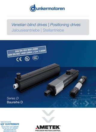
  • 1. Venetian blind drives | Positioning drives Jalousieantriebe | Stellantriebe Series D Baureihe D DIN EN ISO 9001:2008 DIN EN ISO 14001:2004 + Cor 1:2009 sales@electromate.com www.electromate.com ELECTROMATE Toll Free Phone (877) SERVO98 Toll Free Fax (877) SERV099 www.electromate.com sales@electromate.com Sold & Serviced By:
  • 2. 2 | Visit www.dunkermotoren.com for further product information/ Besuchen Sie www.dunkermotoren.de für weitere Produktinformationen To Our Valued Customers, Dunkermotoren is a world class leader in high quality motion control solutions to meet the ever increasing demands for cost effective and reliable drive solutions. Our comprehensive product range offers the flexibility to provide customized solutions as well as standardized components.The catalog represents Dunkermotoren´s years of engineering excellence. The Dunkermotoren Team will continue to utilize our outstanding engineering and industrial capabilities to meet the requirements helping you to succeed. Dunkermotoren Liebe Kunden, als führender Hersteller der Antriebstechnik bieten wir Ihnen wirtschaftliche, effiziente und qualitativ hochwertige Komplettlösungen. Unser umfassendes Produkt- und Leistungsspektrum ermöglicht Ihnen ein hohes Maß an Flexibilität: Ob standardisierte Komponenten oder kundenspezifische Anforderungen – bei uns finden Sie bestimmt die passende Lösung. Mit diesem Katalog können Sie sich einen Überblick über unsere innovativen und richtungsweisenden Produkte verschaffen. Das Dunkermotoren-Team berät Sie gerne engagiert und kompetent. Denn: Ihr Erfolg ist unser Ziel. Dunkermotoren sales@electromate.com www.electromate.com ELECTROMATE Toll Free Phone (877) SERVO98 Toll Free Fax (877) SERV099 www.electromate.com sales@electromate.com Sold & Serviced By:
  • 3. Visit www.dunkermotoren.com for further product information/ Besuchen Sie www.dunkermotoren.de für weitere Produktinformationen | 3 Content/ Inhalt Infos 4 Modular system/ Modulares Baukastensystem 5 Applications/ Anwendungen 16-17 Electrical connections for drives (Venetian-blind and positioning drive)/ Elektrischer Anschluss der Antriebe (Jalousie-und Stellantriebe) 19-23 Setting instructions/ Einstellanweisung 24 Clutches/ Kupplungen 25 Accessories/ Zubehör Venetianblind& Positioningdrives/ Jalousie-& Stellantriebe 6-7 Venetian blind drives/ Jalousieantriebe 8-9 Electronic venetian blind drives/ Elektronische Jalousieantriebe 10-11 SMI technology/ SMI Technologie 12-13 DC drives for interior blinds/ DC-Antriebe innenliegender Sonnenschutz 14-15 Positioning drives/ Stellantriebe sales@electromate.com www.electromate.com ELECTROMATE Toll Free Phone (877) SERVO98 Toll Free Fax (877) SERV099 www.electromate.com sales@electromate.com Sold & Serviced By:
  • 4. 4 | Visit www.dunkermotoren.com for further product information/ Besuchen Sie www.dunkermotoren.de für weitere Produktinformationen Modular system/ Modulares Baukastensystem I/O Condition m oni- toring Power modul BG 75 | 500 Watt Current mode Motor control Power modul BG 95 | 1100 Watt Power modul BG 65 | 180 Watt Power modul BG 45 | 90 Watt M ains connection 230 VAC 3x400 VAC Interface for encoder Functional safty STO SIL 2/3 MI | master functionality Speed mode Position mode Service interface µC Pow erfactor com pensation 6...325 VDC Flexibility, delivery performance and complete motion solutions Standardized motors, gears and modular accessories are available with a higher degree of flexibility to address specific requirements in complete motion solutions. Flexibilität, Lieferperformance und umfassende Antriebslösungen Die Produktpalette von Dunkermotoren ist so aufgebaut, dass sich mit standardisierten Motoren und einem modular aufgebauten Zubehör eine hohe Flexibilität für umfassende Antriebslösungen ergibt. Motion control 4.0 »» Motors carry out tasks autonomously »» Motors monitor their own state and gain information from their local environment »» Motors communicate with other devices and with control/ SCADA level »» Motors adapt flexibly to new tasks Motion Control 4.0 »» Motoren führen autonom Aufgaben aus »» Motoren überwachen ihren Zustand und sammeln Informationen aus der Umgebung »» Motoren kommunizieren mit anderen Geräten und mit der Steuerungs bzw. SCADA Ebene »» Motoren passen sich flexibel an neue Aufgaben an ENCODERS/ GEBER BRAKES/ BREMSEN Tacho generators/ Tachogeneratoren 3 -10 V/ 1.000 min-1 Power-on Brakes/ Arbeitsstrombremsen 0.2 - 1 Nm Power-off Brakes/ Ruhestrombremsen 0.2 - 6 Nm GEARBOXES/ GETRIEBE dGo dMove dPro Incremental Encoder/ Inkrementalgeber up to 4096 ppr MOTORS/ MOTOREN INTEGRATED CONTROLLER/ INTEGRIERTE ELEKTRONIK Magnetic Pulse Generators/ Magnetische Impulsgeber 4 ppr Permanent Magnet DC-Motors/ Bürstenbehaftete Gleichstrommotoren 3 - 240 Watt AC-Motors/ Wechselstrom- Drehstrommotoren 5 - 100 Watt Linear Motors/ Linearmotoren 19 - 1860 N Brushless DC-Servomotors/ Bürstenlose Gleichstrommotoren 6 - 1100 Watt Worm Gearboxes/ Schneckengetriebe 0.75 - 30 Nm Planetary Gearboxes/ Planetengetriebe 0.3 - 160 Nm Spirotec Gearboxes/ Spirotecgetriebe 9 Nm sales@electromate.com www.electromate.com ELECTROMATE Toll Free Phone (877) SERVO98 Toll Free Fax (877) SERV099 www.electromate.com sales@electromate.com Sold Serviced By:
  • 5. Visit www.dunkermotoren.com for further product information/ Besuchen Sie www.dunkermotoren.de für weitere Produktinformationen | 5 Some Applications »» Industrial Automation »» Robots and Logistics »» Wood »» Printing »» Paper »» Textile »» Food beverage »» Packaging »» Semiconductor »» Material handling »» Medical devices laboratory equipment »» Door automation »» Renewable energies »» Motive »» Pumps »» Sun protection Beispiele für Anwendungen »» Industrielle Automatisierung »» Robotik und Logistik »» Holzbearbeitung »» Druckindustrie »» Papierindustrie »» Textilmaschinen »» Lebensmittelmaschinen »» Verpackungsmaschinen »» Halbleiterindustrie »» Materialhandling »» Medizin- und Labortechnik »» Türautomation »» Erneuerbare Energien »» Motive »» Pumpen »» Sonnenschutz Applications/ Anwendungen sales@electromate.com www.electromate.com ELECTROMATE Toll Free Phone (877) SERVO98 Toll Free Fax (877) SERV099 www.electromate.com sales@electromate.com Sold Serviced By:
  • 6. 6 | Visit www.dunkermotoren.com for further product information/ Besuchen Sie www.dunkermotoren.de für weitere Produktinformationen » Single-phase capacitor motors for short time operation with mounted gear box » Solidly designed and maintenance free for life » With comfortable adjustment of the end positions » Single- and double shaft motors are available » With integrated (built in) temperature switch » With integrated electro magnetical brake » With cable 0.5m and mounted connector » Wechselstrom-Induktionsmotoren für Kurzzeitbetrieb mit angebautem Getriebe » Robust und wartungsfrei » Mit Komfort-Endlageneinstellung » End- und Mittelmotoren erhältlich » Mit eingebautem Temperaturwächter » Mit eingebauter elektromagnetischer Bremse » Mit Motorkabel 0,5m und angegossener Steckerverbindung Data/ Technische Daten Motortype/ Motortyp D259 / D258 D359 / D358 D839 / D838 D539 D339 120V D839 120V Operation mode/ Betriebsart KB 4 Min. KB 4 Min. KB 4 Min. KB 6 Min. KB 4 Min. KB 4 Min. Input rated voltage/ Anschlussspannung VAC 230 230 230 230 120 120 Frequenz/ Frequenz Hz 50 50 50 50 60 60 Rated continuous current/ Nennstromaufnahme A 0.42 0.58 0.97 0.51 1.21 1.8 Rated input power/ Nennleistungsaufnahme W 95 132 218 115 132 216 Continuous rated speed/ Nenndrehzahl min-1 23 22 23 23 28 28 Continuous rated torque/ Nenndrehmoment Nm 2x3 2x5 2x9.5 10 2x4 2x8 Starting torque/ Anlaufmoment Nm 2x3 2x5 2x9.5 10 2x4 2x8 Starting input current/ Anlaufstrom A 0.57 0.7 1.3 0.6 1.5 2.2 Capacitor/ Kondensator μF 3 4 7 4 14 23 Weight/ Gewicht kg 1.85 1.94 2.7 1.8 2.0 2.7 Maximum range of revolutions/ Max. Anzahl Umdrehungen 67 67 97 97 97 97 Protection class/ Schutzart IP 54 54 54 54 54 54 Temperature range/ Temperaturbereich °C -20 ... +60 -20 ... +60 -20 ... +60 -20 ... +60 -20 ... +60 -20 ... +60 Insulation class/ Isolierstoffklasse F (155 °C) F (155 °C) F (155 °C) F (155 °C) F (155 °C) F (155 °C) VDE mark/ VDE Zeichen VDE EMC mark/ VDE-EMV Zeichen CE mark/ CE-Zeichen CCC/ CCC UL mark/ UL-Zertifizierung Venetian blind drives/ Jalousieantriebe » D259 | D359 | D339 | D839: adjustable lower and upper end position, additional external limit switch for the upper end position » D258 | D358 | D838: two lower end positions, external limit switch for the upper end postion » D259 | D359 | D339 | D839: untere und obere Endlage einstellbar, zusätzlich Auflaufendschalter für die obere Endlage » D258 | D358 | D838: untere Endlage Doppelendschalter, obere Endlage Auflaufendschalter » D258, D358, D838 Venetian Blind Drives with two lower end position switches (Venetian Blind Drives with two lower end position switches are used in installations with operating position (interconnection venetian blinds). The venetian blinds move with slats in open position down to the first lower end posi- tion switch (AB1). With an additional move- down command the venetian blinds move to the second end position switch (AB2); the slats close.) » D258, D358, D838 Jalousieantriebe mit zwei unteren End- schaltern (Jalousieantriebe mit zwei unteren Endschal- tern werden bei Anlagen mit Arbeitsstellung (Verbundjalousien) eingesetzt. Hierbei fahren die Jalousien in einer geöffneten Stellung der Lamellen nach unten bis auf den ersten unteren Endschalter (AB1). Durch einen weiteren AB-Befehl fahren die Jalousien auf die zweite untere Endlage (AB2); die Lamellen werden geschlossen.) Operating position (slats opened)/ Arbeitsstellung (Lamellen geöffnet) Closed position/ Schließstellung Venetian Blind Drives Jalousieantriebe • D248, D348, D838 Venetian Blind Drives with two lower end position switches (Venetian Blind Drives with two lower end position switches are used in instal- lations with operating position (intercon- nection venetian blinds). The venetian blinds move with slats in open position down to the first lower end position switch (AB1). With an additional move- down command the venetian blinds move to the second end position switch (AB2); the slats close.) • J E (J E A e s L u e d E g AB1 operating position (slats opened) Arbeitsstellung (Lamellen geöffnet) AB2 closed position Schließstellung Venetian Blind Drives Jalousieantriebe • D248, D348, D838 Venetian Blind Drives with two lower end position switches (Venetian Blind Drives with two lower end position switches are used in instal- lations with operating position (intercon- nection venetian blinds). The venetian blinds move with slats in open position down to the first lower end position switch (AB1). With an additional move- down command the venetian blinds move to the second end position switch (AB2); the slats close.) • D248, D348, D83 Jalousieantriebe m Endschaltern (Jalousieantriebe m Endschaltern werd Arbeitsstellung (Ve eingesetzt. Hierbei sien in einer geöffn Lamellen nach unte unteren Endschalte einen weiteren AB die Jalousien auf d Endlage (AB2); die geschlossen.) AB1 operating position (slats opened) Arbeitsstellung (Lamellen geöffnet) AB2 closed position Schließstellung D259 | D359 sales@electromate.com www.electromate.com ELECTROMATE Toll Free Phone (877) SERVO98 Toll Free Fax (877) SERV099 www.electromate.com sales@electromate.com Sold Serviced By:
  • 7. Visit www.dunkermotoren.com for further product information/ Besuchen Sie www.dunkermotoren.de für weitere Produktinformationen | 7 Venetian blind drives/ Jalousieantriebe D259 | D258 | D359 | D358 7 D249 / D248 / D349 / D348 Maße D339 (110 )/ D839 (110 V)/ D839 I1 240 275 I2 182 217 I3 152.5 187.5 I4 146.5 181.5 I5 142 177 + 1.6 - 1 + 1.5 - 1 + 1.5 - 0.7 + 1.2 - 0.5 + 1.2 - 0.5 Dimensions D539 on request available / Maßbild 539 auf Anfrage erhältlich D339 (120V) | D839 (120V) | D839 7 D339 (120 V) / D839 (120 V) / D839 D249 / D248 / D349 / D348 Maße D339 (110 )/ D839 (110 V)/ D839 I1 240 275 I2 182 217 I3 152.5 187.5 I4 146.5 181.5 I5 142 177 + 1.6 - 1 + 1.5 - 1 + 1.5 - 0.7 + 1.2 - 0.5 + 1.2 - 0.5 Venetian Blind Drives Jalousieantriebe • D248, D348, D838 Venetian Blind Drives with two lower end position switches (Venetian Blind Drives with two lower end position switches are used in instal- lations with operating position (intercon- nection venetian blinds). The venetian blinds move with slats in open position down to the first lower end position switch (AB1). With an additional move- down command the venetian blinds move to the second end position switch (AB2); the slats close.) • D248, D348, D838 Jalousieantriebe mit zwei unteren Endschaltern (Jalousieantriebe mit zwei unteren Endschaltern werden bei Anlagen mit Arbeitsstellung (Verbundjalousien) eingesetzt. Hierbei fahren die Jalou- sien in einer geöffneten Stellung der Lamellen nach unten bis auf den ersten unteren Endschalter (AB1). Durch einen weiteren AB-Befehl fahren die Jalousien auf die zweite untere Endlage (AB2); die Lamellen werden geschlossen.) AB1 operating position (slats opened) Arbeitsstellung (Lamellen geöffnet) AB2 closed position Schließstellung Dimensions D539 on request available / Maßbild 539 auf Anfrage erhältlich Dimensions/ Maße D339 (110V) D839 (110V)/ D839 I1 + 1.6 | - 1 240 275 I2 + 1.5 | - 1 182 217 I3 + 1.5 | - 0.7 152.5 187.5 I4 + 1.2 | - 0.5 146.5 181.5 I5 + 1.2 | - 0.5 142 177 D539 sales@electromate.com www.electromate.com ELECTROMATE Toll Free Phone (877) SERVO98 Toll Free Fax (877) SERV099 www.electromate.com sales@electromate.com Sold Serviced By:
  • 8. 8 | Visit www.dunkermotoren.com for further product information/ Besuchen Sie www.dunkermotoren.de für weitere Produktinformationen Expanded capability profile in comparison with traditional motors based on AC motors with mechanical end limit switches. » Slow speed at each start in each direction of rotation enables a sensitive setting of the slat angle thus an optimized controlling of the insolation » The load-independent speed control keeps the speed constant for the whole height of the blind. As a result of this the view of the running of the blind is consistent » A new concept of the braking system eliminates disturbing braking noises » For the comfortable adjustment of the end position it is not necessary to have direct access to the motor by using the manual control device of Dunkermotoren » Several motors can be connected in parallel » Storage of the travel command after operation of the up our down button for more than 3 seconds » Because of the integration of many functions which have been realized in the past with external control devices the motor can be controlled by very easy control devices Erweitertes Leistungsspektrum gegenüber klassischen Jalousieantrieben auf Wechselstrombasis mit mechanischen Endschaltern. » Schleichdrehzahl für ca. 3 Sek. bei jedem Anfahren ermöglicht eine feinfühlige Einstellung des Lamellenwinkels und somit optimale Steuerung der Sonneneinstrahlung » Die lastunabhängige Drehzahlregelung hält die Drehzahl über die gesamte Behanghöhe konstant und führt so zu einem einheitlichen Behanglaufbild insbesondere bei großen Fassaden mit vielen Jalousien » Ein neues Bremskonzept eliminiert störende Bremsgeräusche » Die Einstellung der Endlagen erfolgt komfortabel über ein Steuerkabel, ohne daß der Motor zugänglich sein muß » Mehrere Motoren können über einen Taster parallel geschaltet werden » Speicherung (Selbsthaltung) der Fahrbefehle nach Drücken der Auf- oder Ab-Taste länger als 3 Sekunden » Durch die Intergration vieler Funktionen in den Antrieb, welche bisher in den Motorsteuergeräten enthalten sind, können zur Steuerung des Motors einfachste Steuergeräte verwendet werden Electronic venetian blind drives/ Elektronische Jalousieantriebe Data/ Technische Daten Motortype/ Motortyp D370 / D370 SMI Input rated voltage/ Anschlussspannung VAC 230 Frequenz/ Frequenz Hz 50 Continuous rated torque/ Nenndrehmoment Nm 2x5* Slow speed/ Schleichgang min-1 5 Fast speed/ Schnellgang min-1 23 Rated continuous current/ Nennstromaufnahme A~ 2x3 Rated input power/ Nennleistungsaufnahme W 92 Maximum range of revolutions/ Max. Anzahl Umdrehungen 140 Starting torque/ Anlaufmoment Nm 2x5 Maximum current/ Maximale Stromaufnahme A 0.82 Weight/ Gewicht kg 1.3 Protection class/ Schutzart IP 54 VDE mark/ VDE Zeichen VDE EMC mark/ VDE-EMV Zeichen CE mark/ CE-Zeichen sales@electromate.com www.electromate.com ELECTROMATE Toll Free Phone (877) SERVO98 Toll Free Fax (877) SERV099 www.electromate.com sales@electromate.com Sold Serviced By:
  • 9. Visit www.dunkermotoren.com for further product information/ Besuchen Sie www.dunkermotoren.de für weitere Produktinformationen | 9 Electronic venetian blind drives/ Elektronische Jalousieantriebe D370 | D370 SMI 9 Electronic Venetian Blind Drives Elektronische Jalousieantriebe D370 / D370 SMI D470 / D470 SMI sales@electromate.com www.electromate.com ELECTROMATE Toll Free Phone (877) SERVO98 Toll Free Fax (877) SERV099 www.electromate.com sales@electromate.com Sold Serviced By:
  • 10. 10 | Visit www.dunkermotoren.com for further product information/ Besuchen Sie www.dunkermotoren.de für weitere Produktinformationen SMI technology/ SMI-Technik The SMI interface defines a standard and robust link between roller shutter/venetian blind drives and control units. Low cost but effective interface circuits are built into the SMI drive and the SMI control unit. These match up to the building’s demanding requirements. SMI drives have 5-core leads. Three cores are for the power supply and the earthing (L, N and PE) and two cores are for the data transfer. The data transfer is so robust that no special types of leads are required. In addition the power supply and the data transfer (I+ and I-) can coexist in the same lead. The data signal leads are protected against any polarity reversal so that no incorrect connection can destroy a drive. The input circuit is protected against overvoltage so that no destruction is possible if high interference voltages occur. Thanks to the ingenious SMI circuit interface, lead lengths of up to 350 m can be accommodated. This means there are virtually no limitations that have to be taken into account during the planning. Data signal transfers take place at 2,400 bits per second. Together with the very efficient standard commands this ensures fast response times. A parallel connection of up to 16 drives to the same motor control unit is possible. Thanks to a global addressing it is possible to have just one start-up in a wired system. The drives can be addressed together or individually, i.e. the allocation of one address per drive is possible, but is not necessary if all the drives are to be controlled together. For further information please see at www.standard-motor-interface.com Die SMI-Schnittstelle definiert eine einheitliche und robuste Verbindung zwischen Rollladen-/Jalousieantrieben und Steuerungen. Jeweils im SMI-Antrieb und in der SMI-Steuerung sind kostengünstige, aber wirkungsvolle Interfaceschaltungen eingebaut, die den anspruchsvollen Anforderungen im Gebäude entsprechen. SMI-Antriebe haben Anschlussleitungen mit 5 Adern. Drei Adern sind für die Stromversorgung und den Schutzleiter (L, N und PE) und zwei Adern sind für die Datenübertragung. Die Datenübertragung ist so robust, dass keine speziellen Leitungstypen erforderlich sind. Zudem können Stromversorgung und Datenübertragung (I+ und I-) in der gleichen Leitung geführt werden. Die Telegrammleitungen sind so verpolsicher, dass ein Falschanschluss keine Zerstörung eines Antriebes zur Folge haben kann. Die Eingangss- chaltung hat eine so hohe Überspannungsfestigkeit, dass auch bei hoher Störspannung keine Zerstörung möglich ist. Dank dem ausgeklügelten SMI-Schaltungsinterface können Leitungslängen bis zu 350m überbrückt werden. Es sind kaum mehr Einschränkungen bei der Planung zu berücksichtigen. Die Telegrammübertragung erfolgt mit 2400 Bit pro Sekunde. Zusammen mit sehr effizienten Standardbefehlen ist eine hohe Reaktionsgeschwindigkeit gesichert. Die Parallelschaltung von bis zu 16 Antrieben an der gleichen Motorsteuerung ist möglich. Dank einer globalen Adresse ist auch eine Inbetriebnahme im verdrahteten System möglich. Die Antriebe können gemeinsam oder einzeln angesprochen werden, d.h. die Vergabe einer Adresse pro Antrieb ist möglich, ist aber bei gemeinsamer Ansteuerung nicht notwendig. Weitere Informationen zur SMI-Technik finden Sie bei www.standard-motor-interface.com Venetian blind drives/ Jalousieantriebe Compatible thanks SMI/ Kompatibel dank SMI Controls device/ Steuerung Building management system SMI drive/ SMI-Antrieb Controls system/ Steuerung sales@electromate.com www.electromate.com ELECTROMATE Toll Free Phone (877) SERVO98 Toll Free Fax (877) SERV099 www.electromate.com sales@electromate.com Sold Serviced By:
  • 11. Visit www.dunkermotoren.com for further product information/ Besuchen Sie www.dunkermotoren.de für weitere Produktinformationen | 11 Selection help for electrical venetian blinds/ Auswahlhilfe für Jalousieantriebe The parameter diagram is a possibility to identify the maximum surface for venetian blinds in dependence of width, height of the blind and torque of the motor. Furthermore the resulting surfaces are depending on the current venetian blinds system. For creating the diagram the following datas are needed: » Take-up spindle radius of lifting band (mm) » Lifting band thickness (mm) » Specific mass of slats (kg/m2) » Specific mass of bottom rail (kg/m) » Safety margin of motor torque (%) » Friction factor (%) For example: Take-up spindle radius of lifting band: 10.5 mm Lifting band thickness: 0.27 mm Specific mass of slats: 1.53 kg/m2 Specific mass of bottom rail: 0.427 kg/m Safety margin of motor torque: 10% Friction factor: 10% On request, Dunkermotoren provides a specific diagram depending on the details (as in the example above mentioned datas) of the venetian blind. Das Parameter-Diagramm dient zur Ermittlung der maximalen Jalousie- fläche in Abhängigkeit von Breite und Höhe der Jalousie sowie vom Motormoment. Die sich ergebenden Flächen sind darüber hinaus abhängig vom jeweiligen Jalousie-System. Zur Erstellung eines Diagrammes benötigen wir folgende Daten: » Wickelkernradius in mm » Zugbanddicke in mm » Gewicht der Lamellen in kg/m2 » Gewicht der Unterschiene (Fallstab) in kg/m » Gewünschte Sicherheit des Motormomentes in % » Reibungsverluste in % Beispiel: Wickelkernradius: 10,5 mm Zugbanddicke: 0,27 mm Gewicht der Lamellen: 1,53 kg/m2 Gewicht der Unterschiene: 0,427 kg/m Sicherheit des Motormomentes: 10% Reibungsverlust: 10% Von Dunkermotoren wird auf Anfrage, abhängig von den Daten (wie im Beispiel oben genannte Daten) der jeweiligen Jalousie, ein spezifisches Diagramm erstellt. Width/ Breite m Height/Höhem Drives/ Antriebe 20.07.2015 Kunde Jalousieart Wickelkernradius in mm: 10,50 mm Zugbanddicke in mm: 0,27 mm Lamellengewicht in kg/qm: 1,58 kg/qm Unterschienengewicht in kg/m: 0,43 kg/m Reibungsfaktor in %: 10% Sicherheitsfaktor in %: 10% 0,00 1,00 2,00 3,00 4,00 5,00 6,00 7,00 0,00 1,00 2,00 3,00 4,00 5,00 6,00 7,00 8,00 9,00 10,00 Höheinm Breite in m 6Nm 9Nm 10Nm 16Nm 20Nm 1 D838, D839 D839 120V D370, D539 D339 120V D258, D259 sales@electromate.com www.electromate.com ELECTROMATE Toll Free Phone (877) SERVO98 Toll Free Fax (877) SERV099 www.electromate.com sales@electromate.com Sold Serviced By:
  • 12. 12 | Visit www.dunkermotoren.com for further product information/ Besuchen Sie www.dunkermotoren.de für weitere Produktinformationen DC drives for interior blinds/ DC-Antriebe innenliegender Sonnenschutz DC Drives for interior blinds The Venetian Blind Drives series DCD22 – based on direct-current technology - are particularly designed for the use in interior blind applications. DCD22-2-G Double shaft drive with integrated incremental encoder. The signals can be interpreted by the use of an external controller and used for end position and velocity control. The upper end position is limited by an external end switch (pushbutton). DCD22-2-E Double shaft drive with integrated controller. The integrated electronics controls upper / lower end position and velocity. The drive is connected to the power supply via an up/ down push-button. The upper and lower end positions are adjustable; an additional external end switch is available for the upper end position. DC-Antriebe innenliegender Sonnenschutz Die Jalousettenatriebe (Jalousieantriebe) der Baureihe DCD22 sind speziell für den Einsatz im innenliegenden Sonnenschutz konzipierte Gleichstromantriebe. DCD22-2-G Antrieb für mittigen Einbau mit integriertem Inkrementalgeber. Die Sig- nale des Inkrementalgebers können durch eine externe Steuerung aus- gewertet und zur Endlagensteuerung und Drehzahlregelung verwendet werden. Die obere Endlage ist durch einen Auflaufendschalter begrenzt. DCD22-2-E Antrieb für mittigen Einbau mit integrierter Steuerelektronik. Die integrierte Steuerelektronik steuert die obere und die untere Endlage und regelt die Drehzahl. Der Antrieb wird über einen Auf-Ab-Taster mit der Spannungsversorgung verbunden. Die obere und untere Endlage sind einstellbar; für die obere Endlage steht zusätzlich ein externer Aufaufendschalter zur Verfügung. Data/ Technische Daten Motortype/ Motortyp DCD22-2-E DCD22-2-G Input rated voltage/ Anschlussspannung VDC 24 24 Continuous rated torque/ Nenndrehmoment Nm 2x0.3 2x0.3 Slow speed/ Schleichgang min-1 5 5* Fast speed/ Schnellgang min-1 32 32* Rated continuous current/ Nennstromaufnahme A 0.32 0.32 Rated input power/ Nennleistungsaufnahme W 7.7 7.7 Maximum range of revolutions/ Max. Anzahl Umdrehungen 400 -* Starting torque/ Anlaufmoment Nm 2x0.3 2x0.3 Maximum current/ Maximale Stromaufnahme A 1.4 1.4 Weight/ Gewicht kg 0.13 0.13 Protection class/ Schutzart IP 40 40 *Depends on controller/ Abhängig von Steuerung sales@electromate.com www.electromate.com ELECTROMATE Toll Free Phone (877) SERVO98 Toll Free Fax (877) SERV099 www.electromate.com sales@electromate.com Sold Serviced By:
  • 13. Visit www.dunkermotoren.com for further product information/ Besuchen Sie www.dunkermotoren.de für weitere Produktinformationen | 13 DC drives for interior blinds/ DC-Antriebe innenliegender Sonnenschutz Dimensions in mm/ Maßzeichnung in mm 13 0,4 0,3 0,2 0,1 torque/Drehmoment Nm 25 20 15 10 5 0 0 0,5 1 1,5 2 2,5 3 1,8 1,6 1,4 1,2 1 0,8 0,6 0,4 0,2 0 Ratedspeed/Drehzahlmin-1 Current/StromA 0 0,2 0,4 0,6 0,8 torque/Drehmoment Nm 70 60 50 40 30 20 10 0 Ratedspeed/Drehzahlmin-1 Characteristic diagram / Belastungskennlinien Dimensions in mm / Maßzeichnung in mm Rated Speed / Drehzahl DCD22-2-G Rated Speed / Drehzahl DCD22-2-E Current / Strom DCD22-2-E Current / Strom DCD22-2-G DC Drives for interior blinds DC-Antriebe innenliegender Sonnenschutz torque/Drehmoment Nm 25 20 15 10 5 0 0 0,5 1 1,5 2 2,5 3 1,8 1,6 1,4 1,2 1 0,8 0,6 0,4 0,2 0 Ratedspeed/Drehzahlmin-1 Current/StromA torque/Drehmoment Nm 25 20 15 10 5 0 0 0,5 1 1,5 2 2,5 3 1,8 1,6 1,4 1,2 1 0,8 0,6 0,4 0,2 0 Ratedspeed/Drehzahlmin-1 Current/StromA 70 60 50 40 30 20 10 0 0 0,2 0,4 0,6 MN 13 0,4 0,3 0,2 0,1 torque/Drehmoment Nm 25 20 15 10 5 0 0 0,5 1 1,5 2 2,5 3 1,8 1,6 1,4 1,2 1 0,8 0,6 0,4 0,2 0 Ratedspeed/Drehzahlmin-1 Current/StromA 0 0,2 0,4 0,6 0,8 torque/Drehmoment Nm 70 60 50 40 30 20 10 0 Ratedspeed/Drehzahlmin-1 Characteristic diagram / Belastungskennlinien Dimensions in mm / Maßzeichnung in mm Rated Speed / Drehzahl DCD22-2-G Rated Speed / Drehzahl DCD22-2-E Current / Strom DCD22-2-E Current / Strom DCD22-2-G DC Drives for interior blinds DC-Antriebe innenliegender Sonnenschutz torque/Drehmoment Nm 25 20 15 10 5 0 0 0,5 1 1,5 2 2,5 3 1,8 1,6 1,4 1,2 1 0,8 0,6 0,4 0,2 0 Ratedspeed/Drehzahlmin-1 Current/StromA torque/Drehmoment Nm 25 20 15 10 5 0 0 0,5 1 1,5 2 2,5 3 1,8 1,6 1,4 1,2 1 0,8 0,6 0,4 0,2 0 Ratedspeed/Drehzahlmin-1 Current/StromA 70 60 50 40 30 20 10 0 0 0,2 0,4 0,6 MN Current/StromA Ratedspeed/Drehzahlmin-1 Characteristic diagram/ Belastungskennlinien sales@electromate.com www.electromate.com ELECTROMATE Toll Free Phone (877) SERVO98 Toll Free Fax (877) SERV099 www.electromate.com sales@electromate.com Sold Serviced By:
  • 14. 14 | Visit www.dunkermotoren.com for further product information/ Besuchen Sie www.dunkermotoren.de für weitere Produktinformationen Positioning drives/ Stellantriebe Positioning drives are motor-gearbox combinations optimised for repeated, short, powerful movements, which are used in lifting tables, solaria, smoke-control shutters, venetian blinds. » With integral, adjustable cut-offs for two end positions » With integral temperature monitoring » With integral electromagnetic brake » With 0.5m motor lead and moulded connector plug Stellantriebe sind Motor-Getriebe-Kombinationen optimal für kurzzeitige und kraftvolle Bewegungen werden u.a. in Hubtischen, Solarien, Rauchklappen, Rolladen, ... eingesetzt. » Mit eingebauter einstellbarer Abschaltung für zwei Endlagen » Mit eingebautem Temperaturwächter » Mit eingebauter elektromagnetischer Bremse » Mit Motorkabel 0,5m und angegossener Steckerverbindung Data/ Technische Daten Motortype/ Motortyp D544 D554 D594 D654S D714S Operation mode/ Betriebsart KB 6 Min. KB 6 Min. KB 6 Min. KB 4 Min. KB 4 Min. Input rated voltage/ Anschlussspannung VAC 230 230 230 230 230 Frequency/ Frequenz Hz 50 50 50 50 50 Continuous rated speed/ Nenndrehzahl rpm 52 23 11 23 110 Rated continuous current/ Nennstromaufnahme A 0.51 0.51 0.51 0.91 0.97 Rated input power/ Nennleistungsaufnahme W 115 115 115 206 218 Continuous rated torque/ Nenndrehmoment Nm 4.4 10 20 19 2x2.4 Maximum radial load/ Max. Radiallast N 1200 1200 1200 1200 - Maximum axial load/ Max. Axiallast N 400 400 400 400 - Starting rated torque/ Anlaufdrehmoment Nm 4.4 10 20 19 2x2.4 Starting input current/ Anlaufstromaufnahme A 0.6 0.6 0.6 1.3 1.3 Capacitor/ Kondensator µF 4.0 4.0 4.0 7.0 7.0 Maximum range of revolutions/ Max. Anzahl Umdrehungen 212 97 44 97 585 Weight/ Gewicht kg ca. 2.2 ca. 2.2 ca. 2.3 ca. 2.8 ca. 2.5 Protection class/ Schutzart IP 54 54 54 54 54 CE mark/ CE Zeichen sales@electromate.com www.electromate.com ELECTROMATE Toll Free Phone (877) SERVO98 Toll Free Fax (877) SERV099 www.electromate.com sales@electromate.com Sold Serviced By:
  • 15. Visit www.dunkermotoren.com for further product information/ Besuchen Sie www.dunkermotoren.de für weitere Produktinformationen | 15 D544 | D554 | D594 17 D544 / D554 / D594 D654S Maße D544 D554 D594 I1 219 229.3 I2 165.2 175.5 I3 126 136.5 + 1.6 - 0.9 + 1.5 - 1 + 1.2 - 0.5 D714S Maße D654s I1 291.3 I2 208.2 I3 176.5 I4 172 + 1.6 - 1 + 1.5 - 1 + 1.5 - 0.7 + 1.2 - 0.7 D654S D714S 17 D544 / D554 / D594 D654S Maße D544 D554 D594 I1 219 229.3 I2 165.2 175.5 I3 126 136.5 + 1.6 - 0.9 + 1.5 - 1 + 1.2 - 0.5 D714S Maße D654s I1 291.3 I2 208.2 I3 176.5 I4 172 + 1.6 - 1 + 1.5 - 1 + 1.5 - 0.7 + 1.2 - 0.7 17 D544 / D554 / D594 D654S Maße D544 D554 D594 I1 219 229.3 I2 165.2 175.5 I3 126 136.5 + 1.6 - 0.9 + 1.5 - 1 + 1.2 - 0.5 D714S Maße D654s I1 291.3 I2 208.2 I3 176.5 I4 172 + 1.6 - 1 + 1.5 - 1 + 1.5 - 0.7 + 1.2 - 0.7 Positioning drives/ Stellantriebe Dimensions/ Maße D544 D554 D594 I1 + 1.6 | - 0.9 219 229.3 I2 + 1.5 | - 1 165.2 175.5 I3 + 1.2 | - 0.5 126 136.5 Dimensions/ Maße D654s I1 + 1.6 | - 1 291.3 I2 + 1.5 | - 1 208.2 I3 + 1.2 | - 0.7 176.5 I4 + 1.2 | - 0.7 172 sales@electromate.com www.electromate.com ELECTROMATE Toll Free Phone (877) SERVO98 Toll Free Fax (877) SERV099 www.electromate.com sales@electromate.com Sold Serviced By:
  • 16. 16 | Visit www.dunkermotoren.com for further product information/ Besuchen Sie www.dunkermotoren.de für weitere Produktinformationen Electrical connections/ Elektrischer Anschluss Venetian blind and positioning drives The single-phase, capacitor motors employed are technically-mature drives which, among other advantages, can be connected directly to an electrical mains supply. However, particularly with regard to connect- ing, there are several points that must be observed to avoid the drive malfunctioning. » For parallel drives incorporating a pair of drives, a two-pole switch must always be used and the connection made as shown in Figure 2 » Direct switching to reverse the direction of rotation should be avoided. Either a switch with a defined “neutral” position or one with a built-in switching delay should be employed. Recommended delay time when changing the direction of rotation: at least 200 milliseconds » Simultaneous up and down commands are not admissible. Only mechanically or electrically interlocked switches may be used » Connection may only be carried out by an authorised electrician » Installation must be carried out in accordance with the current VDE regulations or national regulations specific to the country in which it is located! » The installation must include complete separation of all motor poles from the mains supply, or a two-pole switch with contacts which open at least 3 mm may be employed » A damaged connecting cable has to be replaced by the manufacturer, its service representative or similarly qualified person Jalousie- und Stellantriebe Die verwendeten Einphasen-Kondensator-Motoren sind technisch ausgereifte Antriebe welche u.a. den Vorteil der direkten Anschlußmögli- chkeit an das elektrische Netz bieten. Jedoch sind gerade beim An- schluß einige Hinweise zu beachten, um eine Fehlfunktion der Antriebe auszuschließen. » Bei Parallel-Betrieb zweier Antriebe ist grundsätzlich ein zweipoliger Schalter zu verwenden und der Anschluß entsprechend Bild 2 vorzunehmen » Ein direktes Umschalten der Laufrichtung ist zu vermeiden. Es sind entweder Schalter mit einer ausgeprägten „Null“- Stellung oder mit integrierter Umschaltverzögerung zu verwenden. Empfohlene Pausenzeit bei Drehrichtungswechsel: mind. 200 mSek » Gleichzeitige Auf- und Ab-Befehle sind unzulässig Es dürfen nur mechanisch oder elektrisch verriegelte Schalter verwendet werden » Der Anschluß darf nur von einem konzessionierten Elektriker vorgenommen werden » Für die Installation sind die gültigen VDE bzw.länderspezifischen Vorschriften zu beachten! » Bei der Installation muß eine allpolige Trennung des Motors vom Netz geschaffen werden, oder ein zweipoliger Schalter mit mindestens 3 mm Kontaktöffnungsweite verwendet werden » Eine beschädigte Anschlussleitung ist nur zu ersetzen durch den Hersteller, seinen Kundendienstvertreter oder einer ähnlich qualifizierten Person Figure 1: Connection of a positioning drive using a single-pole switch. Bild 1: Anschluss von einem Stellantrieb über einen einpoli- gen Schalter. D539 | D239 | D339 | D839 | D259 | D544 | D554 | D594 | D654s D258 | D358 | D838 d positioning drives motors employed which, among nnected directly to owever, particularly here are several d to avoid the drive ating a pair of drives, ways be used and hown in Figure 2 e the direction of d. Either a switch osition or one with a ould be employed. when changing the st 200 milliseconds n commands are hanically or tches may be used arried out by an d out in accordance lations or national country in which it is de complete es from the mains ch with contacts may be employed ble has to be Jalousie- und Stellantriebe Die verwendeten Einphasen-Kondensator- Motoren sind technisch ausgereifte Antriebe welche u.a. den Vorteil der direkten Anschluß- möglichkeit an das elektrische Netz bieten. Jedoch sind gerade beim Anschluß einige Hinweise zu beachten, um eine Fehlfunktion der Antriebe auszuschließen. • Bei Parallel-Betrieb zweier Antriebe ist grundsätzlich ein zweipoliger Schalter zu verwenden und der Anschluß entsprechend Bild 2 vorzunehmen • Ein direktes Umschalten der Laufrichtung ist zu vermeiden. Es sind entweder Schalter mit einer ausgeprägten „Null“- Stellung oder mit integrierter Umschaltverzögerung zu ver- wenden. Empfohlene Pausenzeit bei Drehrichtungs- wechsel: mind. 200 mSek • Gleichzeitige Auf- und Ab-Befehle sind unzulässig Es dürfen nur mechanisch oder elektrisch verriegelte Schalter verwendet werden • Der Anschluß darf nur von einem konzessionierten Elektriker vorgenommen werden • Für die Installation sind die gültigen VDE- bzw. länderspezifischen Vorschriften zu beachten! • Bei der Installation muß eine allpolige Trennung des Motors vom Netz geschaffen werden, oder ein zweipoliger Schalter mit mindestens 3 mm Kontaktöffnungsweite verwendet werden • Eine beschädigte Anschlussleitung ist nur zu connections for drives Elektrischer Anschluss der Antriebe Figure 1: Connection of a positioning drive using a single-pole switch. Bild 1: Anschluß von einem Stellantrieb über einen einpoligen Schalter. Figure 2: Connection of two positioning drives using a two-pole switch. Bild 2: Anschluß von zwei Stellantrieben über einen zweipoligen Schalter. Figure 3: Inadmissible connection of two D539/D239/D339/D839/D249/D544/ D554/D594/D654s D539/D239/D339/D839/D249/D544/ D554/D594/D654s d positioning drives otors employed which, among nected directly to wever, particularly ere are several to avoid the drive ting a pair of drives, ays be used and own in Figure 2 the direction of Either a switch sition or one with a uld be employed. when changing the t 200 milliseconds commands are anically or ches may be used rried out by an out in accordance tions or national ountry in which it is e complete s from the mains h with contacts may be employed Jalousie- und Stellantriebe Die verwendeten Einphasen-Kondensator- Motoren sind technisch ausgereifte Antriebe welche u.a. den Vorteil der direkten Anschluß- möglichkeit an das elektrische Netz bieten. Jedoch sind gerade beim Anschluß einige Hinweise zu beachten, um eine Fehlfunktion der Antriebe auszuschließen. • Bei Parallel-Betrieb zweier Antriebe ist grundsätzlich ein zweipoliger Schalter zu verwenden und der Anschluß entsprechend Bild 2 vorzunehmen • Ein direktes Umschalten der Laufrichtung ist zu vermeiden. Es sind entweder Schalter mit einer ausgeprägten „Null“- Stellung oder mit integrierter Umschaltverzögerung zu ver- wenden. Empfohlene Pausenzeit bei Drehrichtungs- wechsel: mind. 200 mSek • Gleichzeitige Auf- und Ab-Befehle sind unzulässig Es dürfen nur mechanisch oder elektrisch verriegelte Schalter verwendet werden • Der Anschluß darf nur von einem konzessionierten Elektriker vorgenommen werden • Für die Installation sind die gültigen VDE- bzw. länderspezifischen Vorschriften zu beachten! • Bei der Installation muß eine allpolige Trennung des Motors vom Netz geschaffen werden, oder ein zweipoliger Schalter mit mindestens 3 mm Kontaktöffnungsweite verwendet werden onnections for drives Elektrischer Anschluss der Antriebe Figure 1: Connection of a positioning drive using a single-pole switch. Bild 1: Anschluß von einem Stellantrieb über einen einpoligen Schalter. Figure 2: Connection of two positioning drives using a two-pole switch. Bild 2: Anschluß von zwei Stellantrieben über einen zweipoligen Schalter. Figure 3: Inadmissible D539/D239/D339/D839/D249/D544/ D554/D594/D654s D539/D239/D339/D839/D249/D544/ D554/D594/D654s Figure 2: Connection of two positioning drives using a two-pole switch. Bild 2: Anschluss von zwei Stellantrieben über einen zweipoligen Schalter. 18 The single-phase, capacitor motors employed are technically-mature drives which, among other advantages, can be connected directly to an electrical mains supply. However, particularly with regard to connecting, there are several points that must be observed to avoid the drive malfunctioning. • For parallel drives incorporating a pair of drives, a two-pole switch must always be used and the connection made as shown in Figure 2 • Direct switching to reverse the direction of rotation should be avoided. Either a switch with a defined “neutral” position or one with a built-in switching delay should be employed. Recommended delay time when changing the direction of rotation: at least 200 milliseconds • Simultaneous up and down commands are not admissible. Only mechanically or electrically interlocked switches may be used • Connection may only be carried out by an authorised electrician • Installation must be carried out in accordance with the current VDE regulations or national regulations specific to the country in which it is located! • The installation must include complete separation of all motor poles from the mains supply, or a two-pole switch with contacts which open at least 3 mm may be employed • A damaged connecting cable has to be replaced by the manufacturer, its service representative or similarly qualified person Die verwendeten Einphasen Motoren sind technisch aus welche u.a. den Vorteil der d möglichkeit an das elektrisc Jedoch sind gerade beim An Hinweise zu beachten, um e Antriebe auszuschließen. • Bei Parallel-Betrieb zweie grundsätzlich ein zweipoli verwenden und der Ansc Bild 2 vorzunehmen • Ein direktes Umschalten d zu vermeiden. Es sind en einer ausgeprägten „Null“ integrierter Umschaltverz wenden. Empfohlene Pausenzeit b wechsel: mind. 200 mSek • Gleichzeitige Auf- und Ab unzulässig Es dürfen nur elektrisch verriegelte Sch werden • Der Anschluß darf nur von konzessionierten Elektrike werden • Für die Installation sind di bzw. länderspezifischen V beachten! • Bei der Installation muß e Trennung des Motors vom werden, oder ein zweipol mindestens 3 mm Kontak verwendet werden • Eine beschädigte Anschlu ersetzen durch den Herst Kundendienstvertreter od qualifizierten Person Figure 1: Connection of a positioning drive using a single-pole switch. Bild 1: Anschluß von einem Stellantrieb über einen einpoligen Schalter. Figure 2: Connection of two positioning drives using a two-pole switch. Bild 2: Anschluß von zwei Stellantrieben über einen zweipoligen Schalter. Figure 3: Inadmissible connection of two positioning drives using a single-pole switch. Bild 3: Unzulässiger Anschluss von zwei Stellantrieben über einen einpoligen Schalter D539/D239/D339/D839/D249/D544/ D554/D594/D654s D539/D239/D339/D839/D249/D544/ D554/D594/D654s D539/D239/D339/D839/D249/D544/ D554/D594/D654s D248/D348/D839 Figure 3: Inadmissible connection of two positioning drives using a single-pole switch. Bild 3: Unzulässiger Anschluss von zwei Stellantrieben über einen einpoligen Schalter. D539 | D239 | D339 | D839 | D259 | D544 | D554 | D594 | D654s D539 | D239 | D339 | D839 | D259 | D544 | D554 | D594 | D654s sales@electromate.com www.electromate.com ELECTROMATE Toll Free Phone (877) SERVO98 Toll Free Fax (877) SERV099 www.electromate.com sales@electromate.com Sold Serviced By:
  • 17. Visit www.dunkermotoren.com for further product information/ Besuchen Sie www.dunkermotoren.de für weitere Produktinformationen | 17 Electronic venetian blind drives D370 | D370 SMI » Installation must be carried out in accordance with the current VDE regulations or national regulations specific to the country in which it is located! » Connection may only be carried out by an authorised electrician » The installation must include complete separation of all motor poles from the mains supply, or a two-pole switch with contacts which open at least 3 mm may be employed » Operation using a controller with “active path control” by monitoring the current draw is not possible, because the current does not pass through the UP and DOWN lines, but through terminal 3 (L1) » A damaged connecting cable has to be replaced by the manufacturer, its service representative or similarly qualified person Elektronische Jalousieantriebe D370 | D370 SMI » Für die Installation sind die gültigen VDE- bzw. länderspezifischen Vorschriften zu beachten! » Der Anschluß darf nur von einem konzessionierten Elektriker vorgenommen werden » Bei der Installation muß eine allpolige Trennung des Motors vom Netz geschaffen werden, oder ein zweipoliger Schalter mit mindestens 3 mm Kontaktöffnungsweite verwendet werden » Eine Bedienung über Ansteuergeräte mit einer „aktiven Wegmessung“ mittels Überwachung der Stromaufnahme ist nicht möglich, da die Stromaufnahme nicht über die AUF- oder AB-Leitung sondern über Klemme 3 (L1) erfolgt » Eine beschädigte Anschlussleitung ist nur zu ersetzen durch den Hersteller, seinen Kundendienstvertreter oder einer ähnlich qualifizierten Person Single operation/ Einzelbetrieb an-blind drives / D470/ D470 SMI d out in accordance ulations or national country in which it carried out by an ude complete les from the le switch with ast 3 mm may be er with monitoring the ble, because the ough the UP and terminal 3 (L1) able has to be urer, its similarly qualified Elektronische Jalousieantriebe D370/ D370 SMI / D470/ D470 SMI • Für die Installation sind die gültigen VDE- bzw. länderspezifischen Vorschriften zu beachten! • Der Anschluß darf nur von einem konzessionierten Elektriker vorgenommen werden • Bei der Installation muß eine allpolige Trennung des Motors vom Netz geschaffen werden, oder ein zweipoliger Schalter mit mindestens 3 mm Kontaktöffnungsweite verwendet werden • Eine Bedienung über Ansteuergeräte mit einer „aktiven Wegmessung“ mittels Überwachung der Stromaufnahme ist nicht möglich, da die Stromaufnahme nicht über die AUF- oder AB-Leitung sondern über Klemme 3 (L1) erfolgt • Eine beschädigte Anschlussleitung ist nur zu ersetzen durch den Hersteller, seinen Kundendienstvertreter oder einer ähnlich qualifizierten Person connections for drives Elektrischer Anschluss der Antriebe Single operation / Einzelbetrieb up down StAS 4 StAK 4 betrieb No earth connection required because of protection class II. Parallel operation/ Parallelbetrieb No earth connection required because of protection class II./ Kein Erdungsanschluss am Motor erforderlich, da der Motor die Schutzklasse II erfüllt. Tomoredrives/ zuweiterenAntrieben 19 Electronic venetian-blind drives D370/ D370 SMI / D470/ D470 SMI • Installation must be carried out in accordance with the current VDE regulations or national regulations specific to the country in which it is located! • Connection may only be carried out by an authorised electrician • The installation must include complete separation of all motor poles from the mains supply, or a two-pole switch with contacts which open at least 3 mm may be employed • Operation using a controller with “active path control” by monitoring the current draw is not possible, because the current does not pass through the UP and DOWN lines, but through terminal 3 (L1) • A damaged connecting cable has to be replaced by the manufacturer, its service representative or similarly qualified person Elektronische Jalousieantriebe D370/ D370 SMI / D470/ D470 SMI • Für die Installation sind die gültigen VDE- bzw. länderspezifischen Vorschriften zu beachten! • Der Anschluß darf nur von einem konzessionierten Elektriker vorgenommen werden • Bei der Installation muß eine allpolige Trennung des Motors vom Netz geschaffen werden, oder ein zweipoliger Schalter mit mindestens 3 mm Kontaktöffnungsweite verwendet werden • Eine Bedienung über Ansteuergeräte mit einer „aktiven Wegmessung“ mittels Überwachung der Stromaufnahme ist nicht möglich, da die Stromaufnahme nicht über die AUF- oder AB-Leitung sondern über Klemme 3 (L1) erfolgt • Eine beschädigte Anschlussleitung ist nur zu ersetzen durch den Hersteller, seinen Kundendienstvertreter oder einer ähnlich qualifizierten Person Electrical connections for drives Elektrischer Anschluss der Antriebe Single operation / Einzelbetrieb up down StAS 4 StAK 4 Parallel operation / Parallelbetrieb StAS 4 StAK 4 StAS 4 StAK 4 up down No earth connection required because of protection class II. Kein Erdungsanschluss am Motor erforderlich, da der Motor die Schutzklasse II erfüllt. tomoredrives zuweiterenAntrieben Electrical connections/ Elektrischer Anschluss sales@electromate.com www.electromate.com ELECTROMATE Toll Free Phone (877) SERVO98 Toll Free Fax (877) SERV099 www.electromate.com sales@electromate.com Sold Serviced By:
  • 18. 18 | Visit www.dunkermotoren.com for further product information/ Besuchen Sie www.dunkermotoren.de für weitere Produktinformationen Notes/ Notizen sales@electromate.com www.electromate.com ELECTROMATE Toll Free Phone (877) SERVO98 Toll Free Fax (877) SERV099 www.electromate.com sales@electromate.com Sold Serviced By:
  • 19. Visit www.dunkermotoren.com for further product information/ Besuchen Sie www.dunkermotoren.de für weitere Produktinformationen | 19 Venetian blind drives D539 | D259 | D359 | D839 | D339 The lower end position has already been set in the factory. In general, an adjustment of the lower end position is not necessary by installation in the lowered venetian blind. 1. Setting the upper end position (U.e.) » Drive the blind to at least 0.5 m* below the desired upper end position » Switch on the venetian blind in the “up” direction and at the same time push the adjustment button 1 (Up) for the time the venetian blind moved approx. 0.5 m* (about 10 sec.). After this time the adjustment button remains snapped in » Continue to run the venetian blind in the desired end position. A fine adjustment is possible by typing on the switch » To fix the adjustment move in the down direction; the adjustment button snaps out 2. Setting the lower end position (L.e.) » Drive the blind to at least 0.5 m* above the desired lower end position » Switch on the venetian blind in the “down” direction and at the same time push the adjustment button 2 for the time the venetian blind moved approx. 0.5 m* (about 10 sec.). After this time the adjustment button remains snapped in » Continue to run the venetian blind in the desired end position. A fine adjustment is possible by typing on the switch » To fix the adjustment move in the up direction; the adjustment button snaps out * By venetian blind lengths more than 1.5 m add approx. 0.2 m per meter Modification of an adjusted end position Run the venetian blind at a sufficient distance (min. 0.5 m) in direction to the new end position. Set new position according to item 1 or 2. Demounting the push button a) lift one of the side snap locks with a thin screw driver. b) press the push button to the side. Do not remove the cover below the push button! Left side installation of single output shaft motors The standard version of the single output shaft units is planned for installation in the right side. In case the unit should be installed in the left side, the left side version has to be ordered! Jalousieantriebe D539 | D259 | D359 | D839 | D339 Die Antriebe sind bei Auslieferung auf die untere Endlage eingestellt. Bei Einbau in die herabgelassene Jalousie ist eine Einstellung der unteren Endlage in der Regel nicht erforderlich. 1. Einstellung der oberen Endlage » Jalousie mindestens 0,5 m* unter die gewünschte obere Endlage fahren » Jalousie in „AUF“-Richtung über Taster fahren, hierbei Einstellknopf 1 für einen Jalausielaufweg von ca. 0,5 m* (ca. 10 Sek.) gedrückt halten, danach selbsthaltend » Jalousie weiter in „AUF“- Richtung in die gewünschte Endlage fahren, Feineinstellung durch Tippen am Taster möglich » Mit „AB“- Befehl Endlageneinstellung fixieren 2. Einstellung der unteren Endlage » Jalousie mindestens 0,5 m* über die gewünschte untere Endlage fahren » Jalousie in „AB“-Richtung über Taster fahren, hierbei Einstellknopf 2 für einen Jalousielaufweg von ca. 0,5 m* (ca. 10 Sek.) gedrückt halten, danach selbsthaltend » Jalousie weiter in „AB“- Richtung in die gewünschte Endlage fahren, Feineinstellung durch Tippen am Taster möglich » Mit „AUF“- Befehl Endlageneinstellung fixieren * Bei Jalousiehöhen über 1,5 m sind pro zusätzlichem Meter ca. 0,2 m hinzuzurechnen Veränderung einer eingestellten Endlage Jalousie in einen ausreichenden Abstand (mind. 0,5 m) vor die neue Endlage fahren. Neue Einstellung entsprechend Punkt 1 oder 2 vornehmen. Demontage des Abschaltpilzes a) Mit dünnem Schraubendreher einen der seitlichen Schnappver- schlüsse anheben. b) Schaltpilz seitlich wegdrücken. Die Abdeckung unter dem Schaltpilz nicht entfernen! Linkseinbau von Endmotoren Standardmäßig sind Endmotoren für den Rechtseinbau vorgesehen. Bei Linkseinbau ist die Ausführung „Linkslauf“ zu bestellen! Setting instructions/ Einstellanweisung ADJUST BUTTONS/ EINSTELLKNÖFPE » UP | Button 1/ AUF | Einstellknopf 1 » DOWN | Button 2/ AB | Einstellknopf 2 Adjustable end position range: 97 revolutions at the drive Dx39 67 revolutions at the drive Dx49 Einstellbarer Endlagenbereich: 87 Umdrehungen am Abtrieb bei Dx39 67 Umdrehungen am Abtrieb bei Dx49 21 Venetian blind drives D539/D239/D339/D839/D249 The lower end position has already been set in the factory. In general, an adjustment of the lower end position is not necessary by installation in the lowered venetian blind. 1. Setting the upper end position (U.e.) • Drive the blind to at least 0.5 m* below the desired upper end position • Switch on the venetian blind in the “up” direction and at the same time push the adjustment button 1 (Up) for the time the venetian blind moved approx. 0.5 m* (about 10 sec.). After this time the adjustment button remains snapped in • Continue to run the venetian blind in the desired end position. A fine adjustment is possible by typing on the switch • To fix the adjustment move in the down direction; the adjustment button snaps out 2. Setting the lower end position (L.e.) • Drive the blind to at least 0.5 m* above the desired lower end position • Switch on the venetian blind in the “down” direction and at the same time push the adjustment button 2 for the time the venetian blind moved approx. 0.5 m* (about 10 sec.). After this time the adjustment button remains snapped in • Continue to run the venetian blind in the desired end position. A fine adjustment is possible by typing on the switch • To fix the adjustment move in the up direction; the adjustment button snaps out * By venetian blind lengths more than 1.5 m add approx. 0.2 m per meter Modification of an adjusted end position Run the venetian blind at a sufficient distance (min. 0.5 m) in direction to the new end position. Set new position according to item 1 or 2. Demounting the push button a) lift one of the side snap locks with a thin screw driver. b) press the push button to the side. Do not remove the cover below the push button! Left side installation of single output shaft motors The standard version of the single output shaft units is planned for installation in the right side. In case the unit should be installed in the left side, the left side version has to be ordered! Jalousieantriebe D539/D239/D339/D839/D249 Die Antriebe sind bei Auslieferung auf die untere Endlage eingestellt. Bei Einbau in die herabgelassene Jalousie ist eine Ein- stellung der unteren Endlage in der Regel nicht erforderlich. 1. Einstellung der oberen Endlage • Jalousie mindestens 0,5 m* unter die gewünschte obere Endlage fahren • Jalousie in „AUF“-Richtung über Taster fahren, hierbei Einstellknopf 1 für einen Jalausielaufweg von ca. 0,5 m* (ca. 10 Sek.) gedrückt halten, danach selbsthaltend • Jalousie weiter in „AUF“- Richtung in die gewünschte Endlage fahren, Feineinstellung durch Tippen am Taster möglich • Mit „AB“- Befehl Endlageneinstellung fixieren 2. Einstellung der unteren Endlage • Jalousie mindestens 0,5 m* über die gewünschte untere Endlage fahren • Jalousie in „AB“-Richtung über Taster fahren, hierbei Einstellknopf 2 für einen Jalousielaufweg von ca. 0,5 m* (ca. 10 Sek.) gedrückt halten, danach selbsthaltend • Jalousie weiter in „AB“- Richtung in die gewünschte Endlage fahren, Feineinstellung durch Tippen am Taster möglich • Mit „AUF“- Befehl Endlageneinstellung fixieren * Bei Jalousiehöhen über 1,5 m sind pro zusätzlichem Meter ca. 0,2 m hinzuzurechnen Veränderung einer eingestellten Endlage Jalousie in einen ausreichenden Abstand (mind. 0,5 m) vor die neue Endlage fahren. Neue Einstellung entsprechend Punkt 1 oder 2 vornehmen. Demontage des Abschaltpilzes a) Mit dünnem Schraubendreher einen der seitlichen Schnappverschlüsse anheben. b) Schaltpilz seitlich wegdrücken. Die Abdeckung unter dem Schaltpilz nicht entfernen! Linkseinbau von Endmotoren Standardmäßig sind Endmotoren für den Rechtseinbau vorgesehen. Bei Linkseinbau ist die Ausführung „Linkslauf“ zu bestellen! Setting instructions Einstellanweisung »UP« Button 1 / »Auf« Einstellknopf 1 »DOWN« Button 2 / »Ab« Einstellknopf 2 Adjustable end position range: 97 revolutions at the drive D x39; 67 revolutions at the drive D x49 Einstellbarer Endlagenbereich: 97 Umdrehungen am Abtrieb bei D x39; 67 Umdrehungen am Abtrieb bei D x49 ADJUSt BUttONS / EINStELLKNöpFE sales@electromate.com www.electromate.com ELECTROMATE Toll Free Phone (877) SERVO98 Toll Free Fax (877) SERV099 www.electromate.com sales@electromate.com Sold Serviced By:
  • 20. 20 | Visit www.dunkermotoren.com for further product information/ Besuchen Sie www.dunkermotoren.de für weitere Produktinformationen Setting instructions/ Einstellanweisung Electronic venetian blind drives D370 | D370 SMI 1. Initial Commissioning On delivery, the drive is in delivery condition: the position of the drive corresponds to the lower stop position. Fit the drive in the lowered venetian blind. Establish power supply. The drive can only be operated in the up direction. The up command initiates the position-learning run; the drive confirms the correct position-learning run by a short stop after 1 sec. Following change-over to fast speed, the drive travels in lock command mode to the external limit switch (push button), whereby this position is stored as the upper end position. After this position-learning run, the upper end position (corresponds to the push button) and the lower stop position are set. Further adjustments are only necessary if different up- per or lower end positions are required (see points 2 and 3). Note on programming: the drive indicates the duration of pushing the programming button by means of a short run both in up and down direction after 2 sec. respectively 5 sec. 2. Setting of the upper end position Run the drive at least 10cm below the desired upper end position. Press the programming button for 2 to 5 sec.; after 2 sec. the drive carries out a short run in up and down direction. Run with the up button (dead man’s mode) to the required upper end position. The drive con- firms the correct programming mode by means of a short stop after a run lasting 1 sec. When the required upper end position is reached, the position is stored by means of the down button: press the down button until the drive confirms the correct storage of the end position by a short stop after a run lasting 1 sec. 3. Setting of the lower end position Run the drive at minimum 10cm above the desired lower end position. Press the programming button for 2 to 5 sec.; after 2 sec. the drive carries out a short run in up and down direction. Run with the down button (dead man’s mode) to the required lower end position. The drive confirms the correct programming mode by means of a short stop after a run lasting 1 sec. When the required lower end position is reached, the position is stored by means of the up button: press the up button until the drive confirms the correct storage of the stop position by a short stop after a run lasting 1 sec. 4. Re-establishing the delivery state Press the programming button for 5 to 10 sec.; after 2 sec. respectively 5 sec., the drive carries out a short run in up and down direction. Briefly release the programming button. Push the programming button for 2 to 5 sec. again; after 2 sec. the drive carries out a short run in up and down direction. Release the programming button. The delivery state is now re-established. Elektronische Jalousieantriebe D370 | D370 SMI 1. Erste Inbetriebnahme Bei Auslieferung befindet sich der Antrieb im Auslieferzustand; die Position des Antriebs entspricht der unteren Endlage. Antrieb in die herabgelassene Jalousie einbauen. Netzanschluß herstellen. Der Antrieb kann nur in Richtung AUF gefahren werden. Durch den AUF-Befehl wird die Positionslernfahrt ausgelöst; der Antrieb bestätigt die korrekte Positionslernfahrt durch einen kurzen Stop nach 1 Sek. Fahrt. Nach Übergang in den Schnellgang fährt der Antrieb in Selbsthaltung auf den externen Endschalter (Pilztaster) wo- durch diese Position als obere Endlage abgespeichert wird. Nach dieser Positionslernfahrt sind die obere Endlage (entspricht Pilztaster) und die untere Endlage eingestellt; weitere Einstellungen sind nur notwendig wenn abweichende obere oder untere Endlagenpositionen gewünscht werden (siehe Pkt. 2 u. 3). Hinweis für die Programmierung: Der Antrieb zeigt die Zeitdauer der Betätigung des Programmiertasters nach 2 Sek. bzw. nach 5 Sek. durch jeweils eine kurze AUF- und AB-Bewegung an. 2. Einstellen der oberen Endlagen Antrieb mind. 10cm unter die gewünschte obere Endlage fahren. Programmiertaster zwischen 2 Sek. und 5 Sek. betätigen; der Antrieb führt nach Ablauf von 2 Sek. eine kurze AUF- und AB-Bewegung aus. Mit AUF-Taster (keine Selbsthaltung) die gewünschte obere Endlage anfahren. Der Antrieb bestätigt den korrekten Programmiermodus durch einen kurzen Stop nach 1 Sek. Fahrt. Nach Erreichen der oberen End- lage diese durch Betätigen des AB-Tasters speichern. Den AB-Taster so lange betätigen, bis der Antrieb das korrekte Speichern der Endlage durch einen kurzen Stop nach ca. 1 Sek. Fahrt bestätigt. 3. Einstellen der unteren Endlagen Antrieb mind. 10cm über die gewünschte untere Endlage fahren. Programmiertaster zwischen 2 Sek. und 5 Sek. betätigen; der Antrieb führt nach Ablauf von 2 Sek. eine kurze AUF- und AB-Bewegung aus. Mit AB-Taster (keine Selbsthaltung) die gewünschte untere Endlage anfahren. Der Antrieb bestätigt den korrekten Programmiermodus durch einen kurzen Stop nach ca. 1 Sek. Fahrt. Nach Erreichen der unteren Endlage diese durch Betätigen des AUF-Tasters speichern. Den AUF- Taster so lange betätigen, bis der Antrieb das korrekte Speichern der Endlage durch einen kurzen Stop nach ca. 1 Sek. Fahrt bestätigt. 4. Wiederherstellen des Auslieferzustandes Programmiertaster zwischen 5 Sek. und 10 Sek. betätigen. (der Antrieb führt nach 2 Sek. und 5 Sek. jeweils eine kurze AUF- und AB-Bewegung aus) Programmiertaster kurz los lassen. Programmier- taster nochmals zwischen 2 Sek. und 5 Sek. betätigen. (Der Antrieb führt nach 2 Sek. eine kurze AUF- und AB-Bewegung aus.) Programmiertaster los lassen. Der Antrieb befindet sich nun im Auslief- erzustand. Electronicvenetianblinddrives D370/D370SMI/D470/D470SMI 1.InitialCommissioning Ondelivery,thedriveisindeliverycondition:theposi- tionofthedrivecorrespondstothelowerstopposition. Fitthedriveintheloweredvenetianblind. Establishpowersupply. Thedrivecanonlybeoperatedintheupdirection. Theupcommandinitiatestheposition-learningrun; thedriveconfirmsthecorrectposition-learningrunby ashortstopafter1sec.Followingchange-overtofast speed,thedrivetravelsinlockcommandmodetothe externallimitswitch(mushroompushbutton),whereby thispositionisstoredastheupperstopposition. Afterthisposition-learningrun,theupperstopposition (correspondstothemushroompushbutton)andthe lowerstoppositionareset.Furtheradjustmentsare onlynecessaryifdifferentupperorlowerstoppositions arerequired(seepoints2and3). Noteonprogramming:thedriveindicatesthedura- tionofpushingtheprogrammingbuttonbymeansof ashortrunbothinupanddowndirectionafter2sec. respectively5sec. 2.Settingoftheupperstopposition Runthedriveatleast10cmbelowthedesiredupper stopposition. Presstheprogrammingbuttonfor2to5sec.;after2 sec.thedrivecarriesoutashortruninupanddown direction. Runwiththeupbutton(deadman’smode)tothe requiredupperstopposition.Thedriveconfirmsthe correctprogrammingmodebymeansofashortstop afterarunlasting1sec. Whentherequiredupperstoppositionisreached,the positionisstoredbymeansofthedownbutton:press thedownbuttonuntilthedriveconfirmsthecorrect storageofthestoppositionbyashortstopafterarun lasting1sec. 3.Settingofthelowerstopposition Runthedriveatminimum10cmabovethedesired lowerstopposition. Presstheprogrammingbuttonfor2to5sec.;after2 sec.thedrivecarriesoutashortruninupanddown direction. Runwiththedownbutton(deadman’smode)tothe requiredlowerstopposition.Thedriveconfirmsthe correctprogrammingmodebymeansofashortstopafterarun lasting1sec. Whentherequiredlowerstoppositionisreached,thepositionis storedbymeansoftheupbutton:presstheupbuttonuntilthe driveconfirmsthecorrectstorageofthestoppositionbyashort stopafterarunlasting1sec. ElektronischeJalousieantriebe D370/D370SMI/D470/D470SMI 1.ErsteInbetriebnahme BeiAuslieferungbefindetsichderAntriebimAus- lieferzustand;diePositiondesAntriebsentsprichtder unterenEndlage. AntriebindieherabgelasseneJalousieeinbauen. Netzanschlußherstellen. DerAntriebkannnurinRichtungAUFgefahrenwerden. DurchdenAUF-BefehlwirddiePositionslernfahrtaus- gelöst;derAntriebbestätigtdiekorrektePositionslernfahrt durcheinenkurzenStopnach1Sek.Fahrt.NachÜber- gangindenSchnellgangfährtderAntriebinSelbsthaltung aufdenexternenEndschalter(Pilztaster)wodurchdiese PositionalsobereEndlageabgespeichertwird. NachdieserPositionslernfahrtsinddieobereEndlage (entsprichtPilztaster)unddieuntereEndlageeingestellt; weitereEinstellungensindnurnotwendigwenn abweichendeobereoderuntereEndlagenpositionen gewünschtwerden(siehePkt.2u.3). HinweisfürdieProgrammierung:DerAntriebzeigtdie ZeitdauerderBetätigungdesProgrammiertastersnach2 Sek.bzw.nach5Sek.durchjeweilseinekurzeAUF-und AB-Bewegungan. 2.EinstellenderoberenEndlagen Antriebmind.10cmunterdiegewünschteobereEnd- lagefahren. Programmiertasterzwischen2Sek.und5Sek.betäti- gen;derAntriebführtnachAblaufvon2Sek.einekurze AUF-undAB-Bewegungaus. MitAUF-Taster(keineSelbsthaltung)diegewünschte obereEndlageanfahren.DerAntriebbestätigtden korrektenProgrammiermodusdurcheinenkurzenStop nach1Sek.Fahrt.NachErreichenderoberenEndlage diesedurchBetätigendesAB-Tastersspeichern.Den AB-Tastersolangebetätigen,bisderAntriebdaskor- rekteSpeichernderEndlagedurcheinenkurzenStop nachca.1Sek.Fahrtbestätigt. 3.EinstellenderunterenEndlagen Antriebmind.10cmüberdiegewünschteuntereEnd- lagefahren. Programmiertasterzwischen2Sek.und5Sek.betäti- gen;derAntriebführtnachAblaufvon2Sek.einekurze AUF-undAB-Bewegungaus. MitAB-Taster(keineSelbsthaltung)diegewünschte untereEndlageanfahren.DerAntriebbestätigtdenkor- rektenProgrammiermodusdurcheinenkurzenStopnachca.1Sek. Fahrt.NachErreichenderunterenEndlagediesedurchBetätigen desAUF-Tastersspeichern.DenAUF-Tastersolangebetätigen,bis derAntriebdaskorrekteSpeichernderEndlagedurcheinenkurzen Stopnachca.1Sek.Fahrtbestätigt. up/down button / AUF-/AB-Taster programming button / Programmiertaster ManualControlDevice Handsteuerkabel up/down button/ auf/ab Taste programming button/ Programmiertaste Manualcontroldevice/ Handsteuerkabel sales@electromate.com www.electromate.com ELECTROMATE Toll Free Phone (877) SERVO98 Toll Free Fax (877) SERV099 www.electromate.com sales@electromate.com Sold Serviced By:
  • 21. Visit www.dunkermotoren.com for further product information/ Besuchen Sie www.dunkermotoren.de für weitere Produktinformationen | 21 Setting instructions/ Einstellanweisung 5. Voltage failure A voltage failure when the drive is stationary has no effect. When the voltage is restored, the stored end positions are available once again in an unchanged state. A voltage failure when the drive is running can lead to an incorrect storage of the current position. In this case, the drive must be run in the up direction for the purpose of a reference run to the push button. A down command is not possible before activation of the push button. The reference run takes place in lock command mode independently of whether it is in lock command mode or dead man’s mode of the running commands. The drive confirms the correct reference run by means a short stop after a run lasting 1 sec. Following activation of the push button, the set end positions are once again available and normal operation can be resumed. Note: unlike the reference run, the upper and the lower end positions are reset in the position-learning run (see point 1). 6. Switching between lock command mode and dead man`s mode of the running commands On delivery, the drives are set as standard to lock command mode of the running commands. Switching from lock command mode and dead man’s mode / vice versa is carried out in accordance with the following sequence: Press the programming button for 2 to 5 sec.; after 2 sec., the drive carries out a short run in up and down direction. Briefly release the pro- gramming button. Press the programming button for 2 to 5 sec. again; after 2 sec. the drive carries out a short run in up and down direction. The drive has now changed into the other mode. 5. Spannungsausfall Ein Netzspannungsausfall bei stehendem Antrieb hat keine Auswirkun- gen. Nach Wiedereinschalten der Spannung stehen die gespeicherten Endlagen ohne Änderung zur Verfügung. Ein Netzspannungsausfall während laufendem Antrieb kann zu nicht korrekter Speicherung der aktuellen Position führen. In diesem Fall muß der Antrieb in AUF-Richtung zum Zwecke einer Referenzfahrt auf den Pilztaster gefahren werden. Ein AB-Befehl ist vor Betätigen des Pilztaster nicht möglich. Die Referenzfahrt erfolgt in Selbsthaltung unabhängig ob Selbsthaltung oder Totmann-Betrieb der Fahrbefehle eingestellt ist. Der Antrieb bestätigt die korrekte Referenzfahrt durch einen kurzen Stop nach ca. 1 Sek. Fahrt. Nach Betätigung des Pilz- tasters stehen die eingestellten Endlagen wieder zur Verfügung und der normale Betrieb kann wieder aufgenommen werden. Anmerkung: Im Gegensatz zur Referenzfahrt wird bei der Positionslern- fahrt (siehe Pkt. 1) die obere und die untere Endlage neu gesetzt. 6. Umschalten zwischen Slebsthaltung und Totmann-Betrieb der Fahrbefehle Die Antriebe sind bei Auslieferung standardmäßig auf Selbsthaltung der Fahrbefehle eingestellt. Das Umschalten von Selbsthaltung auf Totmann-Betrieb bzw. umgekehrt erfolgt gem. nachfolgendem Ablauf. Programmiertaster zwischen 2 Sek. und 5 Sek. betätigen; der Antrieb führt nach 2 Sek. eine kurze AUF- und AB-Bewegung aus. Programmiertaster kurz los lassen. Programmiertaster nochmals zwis- chen 2 Sek. und 5 Sek. betätigen. (Der Antrieb führt nach 2 Sek. eine kurze AUF- und AB-Bewegung aus.) Programmiertaster los lassen. Der Antrieb ist im anderen Zustand. sales@electromate.com www.electromate.com ELECTROMATE Toll Free Phone (877) SERVO98 Toll Free Fax (877) SERV099 www.electromate.com sales@electromate.com Sold Serviced By:
  • 22. 22 | Visit www.dunkermotoren.com for further product information/ Besuchen Sie www.dunkermotoren.de für weitere Produktinformationen Setting instructions/ Einstellanweisung Positioning drive D714s Warning! After every change to a limit switch (switching disc), turn the operating switch to the “0” position. The motor is not suitable for direct connection to an electrical supply. As-delivered condition: “0” position - motor stationary, both end positions are set to the same position, motor cannot run. 0 to 585 revolutions can be selected on the drive shaft. Setting the end positions, motor in as-delivered condition 1. Push the two positioning pins in as far as they will go and turn each clockwise about 45° to its stop. 2. Setting the “clockwise” end position Run to the “clockwise” end position. Turn the positioning pin for “clockwise” anti-clockwise to its end position and release it. 3. Setting the “anti-clockwise” end position Run to the “anti-clockwise” end position. Turn the positioning pin for “anti-clockwise” anti-clockwise to its end position and release it. Please note: If the drive clutch is engaged at one of the end positions, then setting is not required for that position. Changing a pre-set end position subsequently Run to the “clockwise” or “anti-clockwise” end position Never push a positioning pin inwards when it is in an intermediate position - this can damage the cut-off unit! Switch off the power supply to the motor. Push the relevant positioning pin in as far as it will go and turn it clockwise about 45° to its stop. Make the desired change (run to the “clockwise” or “anti clockwise” end position). Turn the positioning pin anti-clockwise to its end position again and release it. Stellantrieb D714s Achtung! Bei jeder Veränderung am Endschalter (Schaltscheiben), Bedienungsschalter in 0-Stellung bringen. Der Motor ist für direkten elektrischen Anschluss nicht geeignet. Lieferzustand: 0-Stellung - Motor steht, beide Endlagen sind auf gleiche Position eingestellt, Motor kann nicht gefahren werden. 0 bis 585 Umdrehungen schaltbar an der Antriebswelle. Einstellung der Endlagen, Motor im Lieferzustand 1. Beide Stellbolzen bis auf Anschlag nach innen drücken und ca. 45° nach rechts bis auf Anschlag drehen. 2. Einstellung der Endlage “Rechtslauf“ Endlage “Rechtslauf“ anfahren. Stellbolzen für “Rechtslauf“ bis auf Anschlag nach links drehen und loslassen. 3. Einstellung der Endlage “Linkslauf“ Endlage “Linkslauf“ anfahren. Stellbolzen für „Linkslauf“ bis auf Anschlag nach links drehen und loslassen. Hinweis: Wird der Antrieb bei einer der beiden Endpositionen eingekuppelt, entfällt die Einstellung hierfür. Nachträgliches Verändern eingestellter Endlagen Endlage “Linkslauf“ oder “Rechtslauf“ anfahren. Keinesfalls die Stell- bolzen in einer Zwischenposition nach innen drücken, da sonst die Abschalteinheit beschädigt wird! Motor spannungslos schalten. Den zugehörigen Stellbolzen bis auf Anschlag nach innen drücken und ca. 45° nach rechts bis auf Anschlag drehen. Gewünschte Änderung vornehmen (Endlage “Rechtslauf“ oder “Linkslauf“ anfahren). Den Stellbolzen wieder auf Anschlag nach links drehen und loslassen. Setting end positions from outside/ Endlageneinstellung von Außen 24 Positioning drive D714s Warning! After every change to a limit switch (switching disc), turn the oper- ating switch to the “0” position. The motor is not suitable for direct connection to an electrical supply. As-delivered condition: “0” position - motor stationary, both end positions are set to the same position, motor cannot run. 0 to 585 revolutions can be selected on the drive shaft. Setting the end positions, motor in as-delivered condition 1. Push the two positioning pins in as far as they will go and turn each clockwise about 45° to its stop. 2. Setting the “clockwise” end position Run to the “clockwise” end position. Turn the positioning pin for “clockwise” anti-clockwise to its end position and release it. 3. Setting the “anti-clockwise” end position Run to the “anti-clockwise” end position. Turn the positioning pin for “anti-clockwise” anti-clockwise to its end position and release it. Please note: If the drive clutch is engaged at one of the end positions, then setting is not required for that position. Changing a pre-set end position subsequently Run to the “clockwise” or “anti-clockwise” end position Never push a positioning pin inwards when it is in an intermediate position - this can damage the cut-off unit! Switch off the power supply to the motor. Push the relevant positioning pin in as far as it will go and turn it clockwise about 45° to its stop. Make the desired change (run to the “clockwise” or “anti clockwise” end position). Turn the position- ing pin anti-clockwise to its end position again and release it. Stellantrieb D714s Achtung! Bei jeder Veränderung am Endschalter (Schaltscheiben), Bedienungsschalter in 0-Stellung bringen. Der Motor ist für direkten elektrischen Anschluss nicht geeignet. Lieferzustand: 0-Stellung - Motor steht, beide Endlagen sind auf gleiche Position eingestellt, Motor kann nicht gefahren werden. 0 bis 585 Umdrehungen schaltbar an der Antriebswelle. Einstellung der Endlagen, Motor im Lieferzustand 1. Beide Stellbolzen bis auf Anschlag nach innen drücken und ca. 45° nach rechts bis auf Anschlag drehen. 2. Einstellung der Endlage “Rechtslauf“ Endlage “Rechtslauf“ anfahren. Stellbolzen für “Rechtslauf“ bis auf Anschlag nach links drehen und loslassen. 3. Einstellung der Endlage “Linkslauf“ Endlage “Linkslauf“ anfahren. Stellbolzen für „Linkslauf“ bis auf Anschlag nach links drehen und loslassen. Hinweis: Wird der Antrieb bei einer der beiden Endpositionen eingekuppelt, entfällt die Einstellung hierfür. Nachträgliches Verändern eingestellter Endlagen Endlage “Linkslauf“ oder “Rechtslauf“ anfahren. Keinesfalls die Stellbolzen in einer Zwischenposition nach innen drücken, da sonst die Abschalteinheit beschädigt wird! Motor spannungslos schalten. Den zugehörigen Stellbolzen bis auf Anschlag nach innen drücken und ca. 45° nach rechts bis auf Anschlag drehen. Gewünschte Änderung vornehmen (Endlage “Rechtslauf“ oder “Linkslauf“ anfahren). Den Stellbolzen wieder auf Anschlag nach links drehen und loslassen. Setting instructions Einstellanweisung Up positioning pin anti-clockwise/ Ab-Stellbolzen Linkslauf Down positioning pin clockwise/ Auf-Stellbolzen Rechtslauf clockwise/ Rechtslauf Gearbox end/ Getriebeseite Setting end positions from outside/ Endlageneinstellung von Außen Clockwise/ Rechtslauf Gearbox end/ Getriebeseite Down positioning pin clockwise/ Auf-Stellbolzen Rechtslauf Up positioning pin anti-clockwise/ Ab-Stellbolzen Linkslauf sales@electromate.com www.electromate.com ELECTROMATE Toll Free Phone (877) SERVO98 Toll Free Fax (877) SERV099 www.electromate.com sales@electromate.com Sold Serviced By:
  • 23. Visit www.dunkermotoren.com for further product information/ Besuchen Sie www.dunkermotoren.de für weitere Produktinformationen | 23 Setting instructions/ Einstellanweisung Positioning drive D5../ D654s Warning! After every change to a limit switch (switching disc), turn the operating switch to the “0” position. The motor is not suitable for direct connection to an electrical supply. As-delivered condition: “0” position, motor stationary Setting the “clockwise” end position a) Turn the white switching disc of the clockwise limit switch two clicks in the direction of the arrow. b) Run the motor to the end position and switch it off. c) Bring the markings on the clockwise switching disc and the motor housing into alignment (they must click into engagement). Setting the “anti-clockwise” end position a) Turn the white switching disc of the anti-clockwise limit switch two clicks in the direction of the arrow. b) Run the motor to the end position and switch it off. c) Bring the markings on the anti-clockwise switching disc and the motor housing into alignment (they must click into engagement). Stellantrieb D5../D654s Achtung! Bei jeder Veränderung am Endschalter (Schaltscheiben), Bedienungs- schalter in 0-Stellung bringen. Motor ist für direkten elektrischen Anschluß nicht geeignet. Lieferzustand: 0-Stellung - Motor steht Einstellung der Endlage -Rechtslauf a) Die weiße Schaltscheibe des R-Endschalters um 2 Rasten in Pfeilrichtung drehen. b) Motor in Endlage fahren und abschalten. c) Markierungen der R-Schaltscheiben und Motorgehäuse in Deckung bringen (Rasten). Einstellung der Endlage -Linkslauf a) Die weiße Schaltscheibe des L-Endschalters um 2 Rasten in Pfeilrichtung drehen. b) Motor in Endlage fahren und abschalten. c) Markierungen der L-Schaltscheiben und Motorgehäuse in Deckung bringen (Rasten). 25 Positioning drive D5../D654s Warning! After every change to a limit switch (switching disc), turn the operating switch to the “0” position. The motor is not suitable for direct connection to an electrical supply. As-delivered condition: “0” position, motor stationary Setting the “clockwise” end position a) Turn the white switching disc of the clockwise limit switch two clicks in the direction of the arrow. b) Run the motor to the end position and switch it off. c) Bring the markings on the clockwise switching disc and the motor housing into alignment (they must click into engagement). Setting the “anti-clockwise” end position a) Turn the white switching disc of the anti-clockwise limit switch two clicks in the direction of the arrow. b) Run the motor to the end position and switch it off. c) Bring the markings on the anti-clockwise switching disc and the motor housing into alignment (they must click into engagement). Stellantriebe D5../D654s Achtung! Bei jeder Veränderung am Endschalter (Schaltscheiben), Bedienungsschalter in 0-Stellung bringen. Motor ist für direkten elektrischen Anschluß nicht geeignet. Lieferzustand: 0-Stellung - Motor steht Einstellung der Endlage -Rechtslauf a) Die weiße Schaltscheibe des R-Endschalters um 2 Rasten in Pfeilrichtung drehen. b) Motor in Endlage fahren und abschalten. c) Markierungen der R-Schaltscheiben und Motorgehäuse in Deckung bringen (Rasten). Einstellung der Endlage -Linkslauf a) Die weiße Schaltscheibe des L-Endschalters um 2 Rasten in Pfeilrichtung drehen. b) Motor in Endlage fahren und abschalten. c) Markierungen der L-Schaltscheiben und Motorgehäuse in Deckung bringen (Rasten). Setting instructions Einstellanweisung D544 / D554 / 594 D654s L anti-clockwise L Linkslauf End position clockwise Endlage Rechtslauf End position anti-clockwise Endlage Linkslauf End position clockwise Endlage Rechtslauf End position anti-clockwise Endlage Linkslauf clockwise / Rechtslauf Gearbox end / Getriebeseite clockwise / Rechtslauf Markierung am Motorgehäuse/ Marking on motor housing Farbmarkierung an den Schaltscheiben/ Coloured marking on switching disc 25 Positioning drive D5../D654s Warning! After every change to a limit switch (switching disc), turn the operating switch to the “0” position. The motor is not suitable for direct connection to an electrical supply. As-delivered condition: “0” position, motor stationary Setting the “clockwise” end position a) Turn the white switching disc of the clockwise limit switch two clicks in the direction of the arrow. b) Run the motor to the end position and switch it off. c) Bring the markings on the clockwise switching disc and the motor housing into alignment (they must click into engagement). Setting the “anti-clockwise” end position a) Turn the white switching disc of the anti-clockwise limit switch two clicks in the direction of the arrow. b) Run the motor to the end position and switch it off. c) Bring the markings on the anti-clockwise switching disc and the motor housing into alignment (they must click into engagement). Stellantriebe D5../D654s Achtung! Bei jeder Veränderung am Endschalter (Schaltscheiben), Bedienungsschalter in 0-Stellung bringen. Motor ist für direkten elektrischen Anschluß nicht geeignet. Lieferzustand: 0-Stellung - Motor steht Einstellung der Endlage -Rechtslauf a) Die weiße Schaltscheibe des R-Endschalters um 2 Rasten in Pfeilrichtung drehen. b) Motor in Endlage fahren und abschalten. c) Markierungen der R-Schaltscheiben und Motorgehäuse in Deckung bringen (Rasten). Einstellung der Endlage -Linkslauf a) Die weiße Schaltscheibe des L-Endschalters um 2 Rasten in Pfeilrichtung drehen. b) Motor in Endlage fahren und abschalten. c) Markierungen der L-Schaltscheiben und Motorgehäuse in Deckung bringen (Rasten). Setting instructions Einstellanweisung D544 / D554 / 594 D654s L anti-clockwise L Linkslauf End position clockwise Endlage Rechtslauf End position anti-clockwise Endlage Linkslauf End position clockwise Endlage Rechtslauf End position anti-clockwise Endlage Linkslauf clockwise / Rechtslauf Gearbox end / Getriebeseite clockwise / Rechtslauf Markierung am Motorgehäuse/ Marking on motor housing Farbmarkierung an den Schaltscheiben/ Coloured marking on switching disc 25 Positioning drive D5../D654s Warning! After every change to a limit switch (switching disc), turn the operating switch to the “0” position. The motor is not suitable for direct connection to an electrical supply. As-delivered condition: “0” position, motor stationary Setting the “clockwise” end position a) Turn the white switching disc of the clockwise limit switch two clicks in the direction of the arrow. b) Run the motor to the end position and switch it off. c) Bring the markings on the clockwise switching disc and the motor housing into alignment (they must click into engagement). Setting the “anti-clockwise” end position a) Turn the white switching disc of the anti-clockwise limit switch two clicks in the direction of the arrow. b) Run the motor to the end position and switch it off. c) Bring the markings on the anti-clockwise switching disc and the motor housing into alignment (they must click into engagement). Stellantriebe D5../D654s Achtung! Bei jeder Veränderung am Endschalter (Schaltscheiben), Bedienungsschalter in 0-Stellung bringen. Motor ist für direkten elektrischen Anschluß nicht geeignet. Lieferzustand: 0-Stellung - Motor steht Einstellung der Endlage -Rechtslauf a) Die weiße Schaltscheibe des R-Endschalters um 2 Rasten in Pfeilrichtung drehen. b) Motor in Endlage fahren und abschalten. c) Markierungen der R-Schaltscheiben und Motorgehäuse in Deckung bringen (Rasten). Einstellung der Endlage -Linkslauf a) Die weiße Schaltscheibe des L-Endschalters um 2 Rasten in Pfeilrichtung drehen. b) Motor in Endlage fahren und abschalten. c) Markierungen der L-Schaltscheiben und Motorgehäuse in Deckung bringen (Rasten). Setting instructions Einstellanweisung D544 / D554 / 594 D654s L anti-clockwise L Linkslauf End position clockwise Endlage Rechtslauf End position anti-clockwise Endlage Linkslauf End position clockwise Endlage Rechtslauf End position anti-clockwise Endlage Linkslauf clockwise / Rechtslauf Gearbox end / Getriebeseite clockwise / Rechtslauf Markierung am Motorgehäuse/ Marking on motor housing Farbmarkierung an den Schaltscheiben/ Coloured marking on switching disc End position/ Endlage Clockwise/ Rechtslauf End position/ Endlage Anti-clockwise/ Linkslauf L Anti-Clockwise/ L Linkslauf Coloured marking on switching disc/ Farbmarkierung an den Schaltscheiben End position/ Endlage Clockwise/ Rechtslauf End position/ Endlage Anti-clockwise/ Linkslauf Marking on motor housing/ Markierung am Motorgehäuse Clockwise/ Rechtslauf Gearbox end/ Getriebeseite Clockwise/ Rechtslauf D654s D544 | D554 | D594 sales@electromate.com www.electromate.com ELECTROMATE Toll Free Phone (877) SERVO98 Toll Free Fax (877) SERV099 www.electromate.com sales@electromate.com Sold Serviced By:
  • 24. 24 | Visit www.dunkermotoren.com for further product information/ Besuchen Sie www.dunkermotoren.de für weitere Produktinformationen Clutches/ Kupplungen Shape of shaft, square/ Wellenformen, 4-kant Shape of shaft, hexagon/ Wellenformen, 6-kant Shape of shaft, grooved/ Wellenformen, Nutwelle 26 Shape of shaft, square/ Wellenformen, 4-kant Shape of shaft, hexagon / Wellenformen, 6-kant Shape of shaft, grooved / Wellenformen Nutwelle Clutches Kupplungen 7.05 10.0512.05 7.05 10.05 12.05 7.05 8.05 11.05 14.05 14.05 11.3 10.5 round nut / runde Nut square nut / eckige Nut Dx39 / Dx38: SNR 27576 52049 Dx49 / Dx48: Adapter/Einsatz SNR 27576 41601 in SNR 27576 52112 (Coupling/Kupplung 4-kant 12 mm) Dx39 / Dx38: SNR 27576 52112 Dx49 / Dx48: SNR 27576 52221 Dx39 / Dx38: SNR 27576 52113 Dx49 / Dx48: SNR 27576 52220 Dx39 / Dx38: SNR 27576 52059 Dx39 / Dx38: SNR 27576 52114 Dx39 / Dx38: SNR 27576 52062 Dx39 / Dx38: SNR 27576 52076 Dx49 / Dx48: SNR 27576 52222 Dx39 / Dx38: SNR 27576 52058 Dx49 / Dx48: SNR 27576 52224 Dx39 / Dx38: SNR 27576 52049 Dx59 / Dx58: Adapter/ Einsatz SNR 27576 41601 in SNR 27576 52112 (Coupling/ Kupplung 4-kant 12mm) Dx39 / Dx38: SNR 27576 52112 Dx59 / Dx58: SNR 27576 52221 Dx39 / Dx38: SNR 27576 52113 Dx59 / Dx58: SNR 27576 52220 26 Shape of shaft, square/ Wellenformen, 4-kant Shape of shaft, hexagon / Wellenformen, 6-kant Shape of shaft, grooved / Wellenformen Nutwelle Clutches Kupplungen 7.05 10.0512.05 7.05 10.05 12.05 7.05 8.05 11.05 14.05 14.05 11.3 10.5 round nut / runde Nut square nut / eckige Nut Dx39 / Dx38: SNR 27576 52049 Dx49 / Dx48: Adapter/Einsatz SNR 27576 41601 in SNR 27576 52112 (Coupling/Kupplung 4-kant 12 mm) Dx39 / Dx38: SNR 27576 52112 Dx49 / Dx48: SNR 27576 52221 Dx39 / Dx38: SNR 27576 52113 Dx49 / Dx48: SNR 27576 52220 Dx39 / Dx38: SNR 27576 52059 Dx39 / Dx38: SNR 27576 52114 Dx39 / Dx38: SNR 27576 52062 Dx39 / Dx38: SNR 27576 52076 Dx49 / Dx48: SNR 27576 52222 Dx39 / Dx38: SNR 27576 52058 Dx49 / Dx48: SNR 27576 52224 Dx39 / Dx38: SNR 27576 52059 Dx39 / Dx38: SNR 27576 52114 Dx39 / Dx38: SNR 27576 52062 26 Shape of shaft, square/ Wellenformen, 4-kant Shape of shaft, hexagon / Wellenformen, 6-kant Shape of shaft, grooved / Wellenformen Nutwelle Clutches Kupplungen 7.05 10.0512.05 7.05 10.05 12.05 7.05 8.05 11.05 14.05 14.05 11.3 10.5 round nut / runde Nut square nut / eckige Nut Dx39 / Dx38: SNR 27576 52049 Dx49 / Dx48: Adapter/Einsatz SNR 27576 41601 in SNR 27576 52112 (Coupling/Kupplung 4-kant 12 mm) Dx39 / Dx38: SNR 27576 52112 Dx49 / Dx48: SNR 27576 52221 Dx39 / Dx38: SNR 27576 52113 Dx49 / Dx48: SNR 27576 52220 Dx39 / Dx38: SNR 27576 52059 Dx39 / Dx38: SNR 27576 52114 Dx39 / Dx38: SNR 27576 52062 Dx39 / Dx38: SNR 27576 52076 Dx49 / Dx48: SNR 27576 52222 Dx39 / Dx38: SNR 27576 52058 Dx49 / Dx48: SNR 27576 52224 Round nut/ Runde Nut Dx39 / Dx38: SNR 27576 52076 Dx59 / Dx58: SNR 27576 52222 Square nut/ Eckige Nut Dx39 / Dx38: SNR 27576 52058 Dx59 / Dx58: SNR 27576 52224 sales@electromate.com www.electromate.com ELECTROMATE Toll Free Phone (877) SERVO98 Toll Free Fax (877) SERV099 www.electromate.com sales@electromate.com Sold Serviced By:
  • 25. Visit www.dunkermotoren.com for further product information/ Besuchen Sie www.dunkermotoren.de für weitere Produktinformationen | 25 Fixing screw/ Befestigungsschraube Spacer sleeve/ Distanzbuchse Limit switch extension/ Pilzverlängerung Standard button/ Standard-Schaltkopf Special button for Z profiles/ Schaltkopf für Z-Profile Cable inlet spout/ Kabeldurchführungstülle L1 = 6 mm; L2 = 17 mm SNR 27576 44103 L1 = 11 mm; L2 = 22 mm SNR 27576 44102 L1 = 3.5 mm; L2 = 14.5 mm SNR 27576 44104 L1 = 4.5 mm SNR 27576 17001 L1 = 10 mm SNR 27576 17002 L1 = 2 mm SNR 27576 17004 L1 = 10 mm SNR 27576 12047 L1 = 30 mm SNR 27576 12048 black/ schwarz SNR 27576 83036 black/ schwarz SNR 27576 83039 SNR 27576 57010 Fixing components for various head rails on request/ Befestigungsmaterial für verschiedene Kopfschienen auf Anfrage 27 Accessories Zubehör Fixing screw / Befestigungsschraube Special button for z profiles / Schaltkopf für Z-Profil Fixing components for various head rails on request / Befestigungsmaterial für verschiedene Kopfschienen auf Anfrage Spacer sleeve / Distanzbuchse Cable inlet spout / Kabeldurchführungstülle SNR 22431 57010 Limit switch extension / Pilzverlängerung Standard button / Standard-Schaltkopf L1 = 6 mm; L2 = 17 mm SNR 27576 44103 L1 = 11 mm; L2 = 22 mm SNR 27576 44102 L1 = 3.5 mm; L2 = 14.5 mm SNR 27576 44104 L1 = 4.5 mm SNR 27576 17001 L1 = 10 mm SNR 27576 17002 L1 = 2 mm SNR 27576 17004 L1 = 10 mm SNR 27576 12047 L1 = 30 mm SNR 27576 12048 black/schwarz SNR 27576 83036 black/schwarz SNR 27576 83039 27 Accessories Zubehör Fixing screw / Befestigungsschraube Special button for z profiles / Schaltkopf für Z-Profil Fixing components for various head rails on request / Befestigungsmaterial für verschiedene Kopfschienen auf Anfrage Spacer sleeve / Distanzbuchse Cable inlet spout / Kabeldurchführungstülle SNR 22431 57010 Limit switch extension / Pilzverlängerung Standard button / Standard-Schaltkopf L1 = 6 mm; L2 = 17 mm SNR 27576 44103 L1 = 11 mm; L2 = 22 mm SNR 27576 44102 L1 = 3.5 mm; L2 = 14.5 mm SNR 27576 44104 L1 = 4.5 mm SNR 27576 17001 L1 = 10 mm SNR 27576 17002 L1 = 2 mm SNR 27576 17004 L1 = 10 mm SNR 27576 12047 L1 = 30 mm SNR 27576 12048 black/schwarz SNR 27576 83036 black/schwarz SNR 27576 83039 27 Accessories Zubehör Fixing screw / Befestigungsschraube Special button for z profiles / Schaltkopf für Z-Profil Fixing components for various head rails on request / Befestigungsmaterial für verschiedene Kopfschienen auf Anfrage Spacer sleeve / Distanzbuchse Cable inlet spout / Kabeldurchführungstülle SNR 22431 57010 Limit switch extension / Pilzverlängerung Standard button / Standard-Schaltkopf L1 = 6 mm; L2 = 17 mm SNR 27576 44103 L1 = 11 mm; L2 = 22 mm SNR 27576 44102 L1 = 3.5 mm; L2 = 14.5 mm SNR 27576 44104 L1 = 4.5 mm SNR 27576 17001 L1 = 10 mm SNR 27576 17002 L1 = 2 mm SNR 27576 17004 L1 = 10 mm SNR 27576 12047 L1 = 30 mm SNR 27576 12048 black/schwarz SNR 27576 83036 black/schwarz SNR 27576 83039 27 Accessories Zubehör Fixing screw / Befestigungsschraube Special button for z profiles / Schaltkopf für Z-Profil Fixing components for various head rails on request / Befestigungsmaterial für verschiedene Kopfschienen auf Anfrage Spacer sleeve / Distanzbuchse Cable inlet spout / Kabeldurchführungstülle SNR 22431 57010 Limit switch extension / Pilzverlängerung Standard button / Standard-Schaltkopf L1 = 6 mm; L2 = 17 mm SNR 27576 44103 L1 = 11 mm; L2 = 22 mm SNR 27576 44102 L1 = 3.5 mm; L2 = 14.5 mm SNR 27576 44104 L1 = 4.5 mm SNR 27576 17001 L1 = 10 mm SNR 27576 17002 L1 = 2 mm SNR 27576 17004 L1 = 10 mm SNR 27576 12047 L1 = 30 mm SNR 27576 12048 black/schwarz SNR 27576 83036 black/schwarz SNR 27576 83039 27 Accessories Zubehör Fixing screw / Befestigungsschraube Special button for z profiles / Schaltkopf für Z-Profil Fixing components for various head rails on request / Befestigungsmaterial für verschiedene Kopfschienen auf Anfrage Spacer sleeve / Distanzbuchse Cable inlet spout / Kabeldurchführungstülle SNR 22431 57010 Limit switch extension / Pilzverlängerung Standard button / Standard-Schaltkopf L1 = 6 mm; L2 = 17 mm SNR 27576 44103 L1 = 11 mm; L2 = 22 mm SNR 27576 44102 L1 = 3.5 mm; L2 = 14.5 mm SNR 27576 44104 L1 = 4.5 mm SNR 27576 17001 L1 = 10 mm SNR 27576 17002 L1 = 2 mm SNR 27576 17004 L1 = 10 mm SNR 27576 12047 L1 = 30 mm SNR 27576 12048 black/schwarz SNR 27576 83036 black/schwarz SNR 27576 83039 27 Accessories Zubehör Fixing screw / Befestigungsschraube Special button for z profiles / Schaltkopf für Z-Profil Fixing components for various head rails on request / Befestigungsmaterial für verschiedene Kopfschienen auf Anfrage Spacer sleeve / Distanzbuchse Cable inlet spout / Kabeldurchführungstülle SNR 22431 57010 Limit switch extension / Pilzverlängerung Standard button / Standard-Schaltkopf L1 = 6 mm; L2 = 17 mm SNR 27576 44103 L1 = 11 mm; L2 = 22 mm SNR 27576 44102 L1 = 3.5 mm; L2 = 14.5 mm SNR 27576 44104 L1 = 4.5 mm SNR 27576 17001 L1 = 10 mm SNR 27576 17002 L1 = 2 mm SNR 27576 17004 L1 = 10 mm SNR 27576 12047 L1 = 30 mm SNR 27576 12048 black/schwarz SNR 27576 83036 black/schwarz SNR 27576 83039 27 Accessories Zubehör Fixing screw / Befestigungsschraube Special button for z profiles / Schaltkopf für Z-Profil Fixing components for various head rails on request / Befestigungsmaterial für verschiedene Kopfschienen auf Anfrage Spacer sleeve / Distanzbuchse Cable inlet spout / Kabeldurchführungstülle SNR 22431 57010 Limit switch extension / Pilzverlängerung Standard button / Standard-Schaltkopf L1 = 6 mm; L2 = 17 mm SNR 27576 44103 L1 = 11 mm; L2 = 22 mm SNR 27576 44102 L1 = 3.5 mm; L2 = 14.5 mm SNR 27576 44104 L1 = 4.5 mm SNR 27576 17001 L1 = 10 mm SNR 27576 17002 L1 = 2 mm SNR 27576 17004 L1 = 10 mm SNR 27576 12047 L1 = 30 mm SNR 27576 12048 black/schwarz SNR 27576 83036 black/schwarz SNR 27576 83039 Accessories/ Zubehör sales@electromate.com www.electromate.com ELECTROMATE Toll Free Phone (877) SERVO98 Toll Free Fax (877) SERV099 www.electromate.com sales@electromate.com Sold Serviced By:
  • 26. 26 | Visit www.dunkermotoren.com for further product information/ Besuchen Sie www.dunkermotoren.de für weitere Produktinformationen Notes/ Notizen sales@electromate.com www.electromate.com ELECTROMATE Toll Free Phone (877) SERVO98 Toll Free Fax (877) SERV099 www.electromate.com sales@electromate.com Sold Serviced By:
  • 27. Visit www.dunkermotoren.com for further product information/ Besuchen Sie www.dunkermotoren.de für weitere Produktinformationen | 27 Notes/ Notizen sales@electromate.com www.electromate.com ELECTROMATE Toll Free Phone (877) SERVO98 Toll Free Fax (877) SERV099 www.electromate.com sales@electromate.com Sold Serviced By: