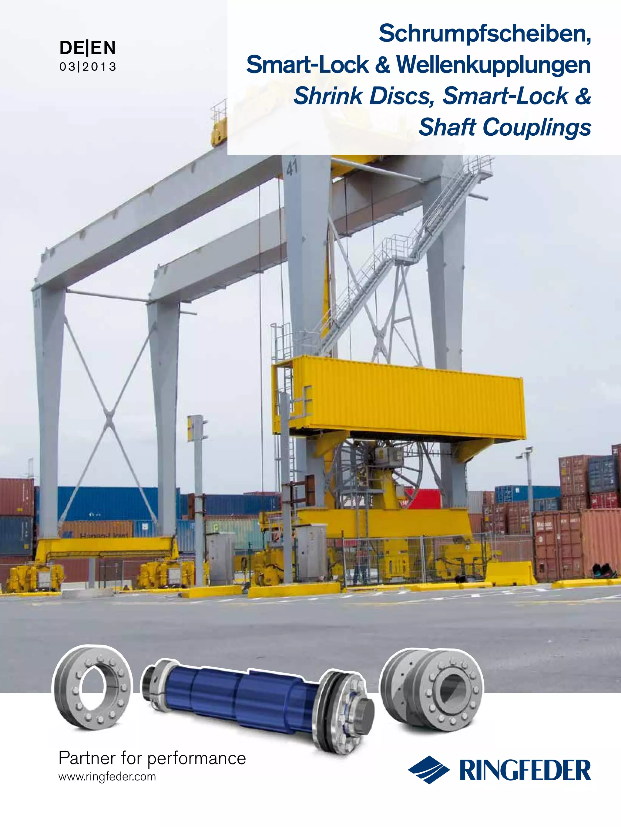
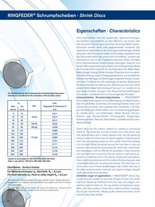
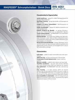
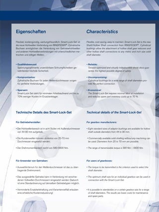
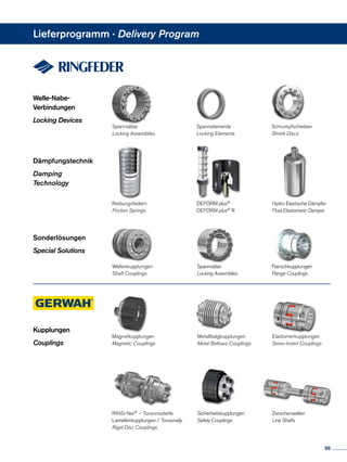
DE|EN
03|2013
Partner for performance
www.ringfeder.com
Schrumpfscheiben,
Smart-Lock & Wellenkupplungen
Shrink Discs, Smart-Lock &
Shaft Couplings
Wir sind für Sie da
A Global Presence For You
Die heutige RINGFEDER POWER TRANS­MISSION GMBH wurde
1922 in Krefeld / Deutschland als Patentverwertungsgesellschaft
für Reibungsfedern gegründet. Heute sind wir ein weltweiter An-
bieter für Spitzenprodukte der Antriebs- und Dämpfungstechnik.
Innovatives Denken in die Grenzbereiche des Möglichen zeichnet
uns aus und hilft uns, mit progressiven und günstigen Lösungen
den technischen Fortschritt unserer Kunden zu unterstützen.
The RINGFEDER POWER TRANSMISSION GMBH was founded
in 1922 in Krefeld, Germany to fabricate and promote Friction
Spring technology. Today we have expanded our offerings to top
power transmission and damping products. Innovative thinking sets
us apart and allows us to develop progressive and economical solu-
tions to support our customers.
2
Besondere Anforderungen erfordern besondere
Anstrengungen
Wir stehen Ihnen mit langjähriger Erfahrung und produktivem En-
gineering zur Verfügung - ob mit Standardprodukten oder auf indi-
viduelle Anfrage. Wir verste­hen Dinge wie außer­­gewöhnlich hohe
Belastbarkeit oder Montage-, Demontagefreund­lichkeit von Bauteilen,
aber auch die Senkung von Fertigungskosten als „Dienst am Kunden“
und entwickeln effiziente und technisch ausgereifte Lösungen.
Special applications require special solutions
Our extensive range of RINGFEDER POWER TRANSMISSION pro-
ducts can be applied to solve most applications. We don´t just sell, but
by understanding the individual requirements of our customers (e.g.
loads on the components, easy installation/removal capability and
reduction of production costs) assist you in every step with innovative
engineering to plan efficient and technically mature solutions.
3
Content
Inhalt
Content
All technical details and information are non-binding and cannot be used as a basis
for legal claims. The user is obligated to determine whether the represented products
meet his requirements. We reserve the right at all times to carry out modifications
in the interests of technical progress. Upon the issue of this catalogue all previous
brochures and questionnaires on the products displayed are no longer valid.
Alle technischen Daten und Hin­weise sind unverbindlich, Rechts­ansprüche können
daraus nicht abgeleitet werden. Der Anwender ist grundsätzlich verpflichtet zu prü-
fen, ob die dargestellten Produkte seinen Anforderungen genügen. Änderungen, die
dem technischen Fortschritt dienen, behalten wir uns jederzeit vor. Mit Erscheinen
dieses Kataloges werden alle älteren Prospekte und Fragebögen zu den gezeigten
Produkten ungültig.
Eigenschaften / Characteristics............................. Seite / Page	8
RINGFEDER® RfN 4012................................................ Seite / Page	10
RINGFEDER® RfN 4022................................................ Seite / Page	 12
RINGFEDER® RfN 4023................................................ Seite / Page	16
RINGFEDER® RfN 4051................................................ Seite / Page	20
RINGFEDER® RfN 4061................................................ Seite / Page	28
RINGFEDER® RfN 4071................................................ Seite / Page	36
RINGFEDER® RfN 4073................................................ Seite / Page	40
RINGFEDER® RfN 4091................................................ Seite / Page	44
RINGFEDER® RfN 4161................................................ Seite / Page	52
RINGFEDER® RfN 4181................................................ Seite / Page	56
RINGFEDER® RfN 4061
Rostfrei/Stainless steel................................................ Seite / Page	60
Schrumpfscheiben
Shrink Discs
4
Inhalt
Content
Content
Inhalt
Content
Smart-Lock
Wellenkupplungen
Shaft Couplings
Eigenschaften / Characteristics............................. Seite / Page	68
RINGFEDER® RfN 4001................................................ Seite / Page	72
Smart-Lock Einzelteile / Parts................................. Seite / Page	76
Eigenschaften / Characteristics............................. Seite / Page	80
RINGFEDER® WK 5071................................................ Seite / Page	82
RINGFEDER® WK 5091................................................ Seite / Page	86
Montage-/Demontageanweisungen
Installation and removal instructions
Schrumpfscheiben / Shrink Discs........................... Seite / Page	90
5
RINGFEDER® Schrumpfscheiben · Shrink Discs
RfN 4071
Standard Reihe
Standard Series
RfN 4073
Mini Reihe
Mini Series
RfN 4091
Schwere Reihe
Heavy Duty Series
RfN 4023
Schwere Reihe
Heavy Duty Series
RfN 4022
Standard Reihe
Standard Series
RfN 4051
Leichte Reihe
Light Duty Series
RfN 4051
Leichte Reihe,
geteilt/halbe
Light Duty Series,
split/half
RfN 4061
Standard Reihe,
geteilt/halbe
Standard Series,
split/half
RfN 4061
Standard Reihe
Standard Series
RfN 4071
Standard Reihe, geteilt/halbe
Standard Series, split/half
RfN 4091
Schwere Reihe, geteilt/halbe
Heavy Duty Series,
split/half
RfN 4181
Schwere Reihe
Heavy Duty Series
RfN 4161
Standard Reihe
Standard Series
RfN 4012
Leichte Reihe
Light Duty Series
6
7
Schrumpfscheiben sind die modernsten Spannverbindungen.
Sie bestehen grundsätzlich, je nach Bauform, aus einem oder
zwei konischen Druckringen und einem Innenring. Mittels Spann­
schrauben werden diese axial gegeneinander verspannt. Der
wesentliche Unterschied zu den Innenspannverbindungen besteht
darin, dass die Pressung von außen auf die Nabe aufgebracht wird.
Die Schrumpfscheibe liegt somit nicht im Kraftfluss, sondern das
Drehmoment wird an der Füge­fläche zwischen Welle und Nabe
ohne Zwischenelement kraftschlüssig übertragen. Dadurch wird
mit der Schrumpfscheibe auf einfache und kostengünstige Weise
ein Presssitz (Schrumpfsitz) für hochbeanspruchte Welle-Nabe-
Verbindungen erzeugt. Bisher mussten Presssitze durch umständ-
liche Berechnung, engste Fertigungstoleranzen und erheblichem
Aufwand bei Montage und Demontage hergestellt werden. Zusätz-
lich treten Probleme bei evtl. notwendig werdenden Reparaturen
(Austauschbarkeit, Einstellung bzw. Zentrierung usw.) auf. Keine
andere Welle-Nabe-Verbindungsart hat auch nur annähernd so
gute Eigenschaften bezüglich der Dauerdrehwechselfestigkeit
aufzuweisen und besitzt einen so hervorragenden Rundlauf.
Unbeschränkte Einsatzmöglichkeiten – RINGFEDER®
Schrumpfscheiben eignen sich zur Befestigung von Nabenkörpern
aller Art auf Wellen und Achsen. Ein­satzmöglichkeiten bieten sich
überall dort, wo bisher Schrumpfsitze, Keil-, Passfeder- und Poly-
gon-Verbindungen, Vielkeilwellen usw. zur Anwendung gelangten.
So werden Zahn- und ­Kettenräder, Hebel, Nocken, Kurven-,
Riemen- oder Bremsscheiben­, Schwungräder, Kupplungen,
Aufsteck­getriebe, Flansche, Seilscheiben, Laufräder absolut zuver-
lässig befestigt.
Shrink discs are the modern method for creating a mechanical
shrink fit. The shrink disc consists of either one or two thrust rings
with tapered bores and a mating tapered inner ring. By tightening
locking screws the thrust rings are drawn together compressing the
inner ring and applying pressure to the outside of the hub clamping
it to the shaft. Being positioned around the hub there is only one
interface transmitting the loads giving the shrink disc method dis-
tinct advantages such as offering the possibility of very concentric
and well balanced connections that are suited to high speed ap-
plications. Traditional shrink fits require complicated calculations,
close machining tolerances and fine surface finishes, they also need
considerable effort with mounting and removal. The shrink disc con-
nection has none of these disadvantages and is better than any of
the other usual connection methods with regard to fatigue strength
under alternating torsional stress.
Unlimited range of applications – RINGFEDER® Shrink Disc
connections are suitable for securing all types of hubs onto shafts
and axles. Replacing traditional shrink fits, keys and polygon con-
nections, splined shafts etc. So cog wheels and sprockets, levers,
lifters, cam discs, pulleys or brake discs, balance wheels, couplings,
slip on gear mechanisms, flanges, pulley wheels and rotors can be
attached absolutely reliable.
Eigenschaften · Characteristics
RINGFEDER® Schrumpfscheiben · Shrink Discs
	dw	
ISO
	max.
	 über	 bis	 Fügespiel S/Clearance S
	 above	 up to	mm
	6	 10		 0,011
	10	 18	 H6/j6	 0,014
	18	 30		 0,017
	30	 50	 H6/h6	 0,032
	50	 80	 H6/g6	 0,048
	80	 120		 0,069
	120	 180		 0,079
	180	 250	 H7/g6	 0,090
	250	 315		 0,101
	315	 400		 0,111
	400	 500		 0,123
	500	 630		 0,136
	 630	800		 0,154
Für die Berechnung der Funktionswerte berücksichtigte Passungen:
Clearances considered for the calculation of the function values:
Es können auch beliebige andere Passungen gewählt werden. Solange dabei das
angegebene max. Fügespiel nicht überschritten wird, ergeben sich keine Funktions-
wertänderungen.
Any other tolerances can be chosen. As long as the stated max. clearance is not
exceeded, there will be no variations of the functional characteristics.
Oberflächen · Surface finishes
Für Wellendurchmesser dw: Rauhtiefe: Ra ≤ 3,2 μm.
For shaft diameter dw: Peak-to-valley height Ra ≤ 3,2 μm.
Tabelle ist nicht gültig für: RfN 4012, RfN 4022, RfN 4023
Table is not valid for: RfN 4012, RfN 4022, RfN 4023
8
Erläuterungen zu Tabellen  Explanations to tables
Basic dimensions when screws are not tightened
d 	 = 	 Inner diameter
D 	 = 	 Outer diameter
dw 	 = 	 Solid shaft diameter
d1 	 = 	 Pitch circle diameter
L 	 =	 Overwall width		
L1 	 =	 Overall width (without screws)
L2 	 =	 Thrust ring width
L3	 =	 Clamping length
Z 	 =	 Depth of center value
TA 	 = 	 Max. tightened torque of the screws
T 	 = 	 Transmissible torque at given TA
Fax	 =	 Transmissible axial force
P 	 =	 Hub surface pressure
σv 	 =	 Equivalent stress in the hub
nSc	=	Quantity of locking screws
G 	 =	 Center diameter
R 	 =	 Corner radius
Tmax 	 = 	 Max. transmissible torque
σv	 =	 Calculated combined stress in the hub
	 extension (d/dw) under consideration of the 	
	 tangential, radial and torsional stresses
	 following the equation:
Grundabmessungen im ungespannten Zustand
d 	 = 	 Innendurchmesser
D 	 = 	 Außendurchmesser
dw 	 = 	 Vollwellen-Durchmesser
d1 	 = 	 Lochkreis-Durchmesser
L 	 =	 Einbaulänge maximal
L1 	 =	 Einbaulänge mind. (ohne Schrauben)
L2 	 =	Druckringbreite
L3	 =	Klemmlänge
Z 	 =	 Tiefe Zentriermaß
TA 	 = 	 Vorgegebenes Anzugsmoment
		 der Spannschrauben
T 	 = 	 Übertragbares Drehmoment bei
		 angegebenem TA
Fax	 =	 Übertragbare Axialkraft	
P 	 =	 Flächenpressung an der Nabe
σv 	 =	 Vergleichsspannung im Nabenansatz
nSc	 =	 Anzahl der Spannschrauben
G 	 =	Zentrierdurchmesser
R 	 =	Eckenradius
Tmax 	 = 	 Max. übertragbares Drehmoment
σv	 =	 Rechnerische Vergleichsspannung im
	Nabenansatz (d/dw) unter Berücksichtigung der 	
	Tangential-,Radial- und Torsions­span­nung nach 	
	 folgender Beziehung:
Zusätzliche Spannungen, z.B. Zug, Druck, Biegung, sind ent-
sprechend zu berücksichtigen.
Funktionswerte
Die Funktionswerte sind in Abhängigkeit der jeweils angege-
benen Anzieh­drehmomente TA bestimmt.
Die Spannschrauben sind mit Schmiermitteln, die MoS2 ent-
halten, geschmiert (µges = 0,1).
Die Konen sind ebenfalls molykotiert (µ = 0,05).
Für die Fuge, Durchmesser dw, wurde der für geölte Montage­
verhältnisse übliche Reibwert µ = 0,12 angesetzt.
Als E-Modul für Welle und Hohlwelle wurde der Wert
210.000 N/mm2 berücksichtigt. (Niedrigere Werte führen
zu einer Erhöhung von T und Fax und einer Reduzierung der
höchsten Einzelspannung, der Tangential­span­nung.)
Für die Berechnung der Funktionswerte wurde das max.
Fügespiel S berücksichtigt, s. nebenstehende Tabelle.
Die Funktionswerte gelten nur bei Verwendung einer Voll-
welle.
Bei der Anwendung einer Außenverspannung auf Hohlwellen
ändern sich die Funktionswerte. Bitte mit unseren Spezia-
listen Rück­sprache nehmen.
Additional loads, e.g. tension, thrust or bending have to be
taken into consideration accordingly.
Function values
The functional characteristics are valid with the screw tighte-
ning torque listed in the tables and the following assumed
conditions:
The locking screws are lubricated using MoS2 (µtot= 0,1).
The tapered cones are lubricated using MoS2 (µ = 0,05).	
The contact surfaces (dw ) are in lightly oiled condition with
coefficient of friction µ = 0,12.
The hub and shaft materials have a modulus of elasticity of
210,000 N/mm2. (Lower values­result in increased values for
T and Fax with reduced tangential stress.)
The maximum clearance S is being fully utilized.
The shaft being used is solid, for hollow shaft applications the
functional values will change.
In cases where the assumed conditions do not apply then
contact our Technical Department where we will be happy to
assist you with your application.
9
RINGFEDER® Schrumpfscheiben · Shrink Discs RfN 4012Leichte Reihe · Light Duty Series
Charakteristische Eigenschaften
Leichtere Ausführung – zur Übertragung kleiner Drehmomente
bei beengten Platzverhältnissen.
Ausgleich von kleinen Toleranzfehlern – bitte Rücksprache
mit unseren Technikern nehmen.
Größte Zuverlässigkeit – geeignet für statische, dynamische
und stoßartige Belastungen.
Einfache Fertigung der Bauteile – nur geringe Anforderungen
an die Funktionsflächen der zu verbindenden Bauteile.
Einfache Montage – kein Absatz, keine Paßfeder, kein Splint
erforderlich. Montierbar an jeder Stelle der Welle mit Standard-
schrauben und handelsüblichen Werkzeugen. Keine zusätzliche
Bearbeitung oder Einpassarbeiten sind erforderlich.
Leichte Demontierbarkeit – nach Lösen der Spannschrauben
ist die RINGFEDER® Schrumpfscheibe selbstlösend und frei auf
der Welle verschiebbar.
Characteristics
Reduced dimensions – for lower transmissible torques, especially
for applications with restricted space.
Compensation of small tolerance errors – please contact our
engineers.
Maximum reliability – suitable for static, dynamic and impact loads.
Simplified manufacture – only plain shaft and bore diameters with
easily achieved surface finish and tolerances are required.
Easy mounting – no steps, keyways, splines are required, therefore
hubs can be located and locked at any point or angle on the shaft.
RINGFEDER® Shrink Discs use standard screws tightened with
standard tools. No additional machining or fitting work is required.
Easy removal – after loosening the locking screws, the
RINGFEDER® Shrink Disc will self release and the hub will move
freely on the shaft.
Bezeichnungen der Bauformen
Description of configurations
RfN 4012 Bauform SDB Gewinde in Schrumpfscheibe mit Zentrieransatz
RfN 4012 configuration SDB thread in shrink disc with centering
L2
Z
x
d1
G
D
d
SDB
RfN 4012 Bauform SDC Durchgangsbohrung in Schrumpfscheibe ohne
Zentrieransatz · RfN 4012 configuration SDC through boring in shrink disc
without centering
L2x
d1
D
d
SDC
RfN 4012 Bauform SDD Durchgangsbohrung in Schrumpfscheibe mit
Zentrieransatz · RfN 4012 configuration SDD through boring in shrink disc
with centering
L2
Z
x
d1
G
D
d
SDD
RfN 4012 Bauform SDA Gewinde in Schrumpfscheibe ohne Zentrieransatz
RfN 4012 configuration SDA thread in shrink disc without centering
L2x
d1
d
D
SDA
10
Baureihe/Series Typ/Type d
RfN 4012 40 SDA 35
RfN 4012 40 SDB 35
RfN 4012 40 SDC 35
RfN 4012 40 SDD 35
Bestellbeispiele · Ordering examples: RfN 4012
x= Bauform	 SDA =	Gewinde in Schrumpfscheibe ohne Zentrieransatz	 SDB = 	Gewinde in Schrumpfscheibe mit Zentrieransatz
Configuration		 Thread in shrink disc without centering		 Thread in shrink disc with centering
	 SDC =	Durchgangsbohrung in Schrumpfscheibe ohne Zentrieransatz	 SDD = 	Durchgangsbohrung in Schrumpfscheibe mit Zentrieransatz
		Through boring in shrink disc without centering		 Through boring in shrink disc with centering
1) Schrumpfscheibe wird ohne Schrauben geliefert. Anzugsmomente für vorgesehene Schraubengröße/-güte siehe Tabelle
Shrink disc delivered without screws. Tigthening torques for srews quantity see table
2) Die Bohrungstoleranz des Kundenbauteils sollte innerhalb der Passungstoleranz G6 und H7 liegen
The bore tolerance of the customer component should be within the fit tolerance G6 and H7	
RfN 4012 Leichte Reihe / Light Duty Series
Typ Abmessungen Schrumpfscheiben Übertragbare Drehmomente Spannschrauben1) Gewicht
Type Shrink discs dimensions Transmissible torques Locking screws Weight
ISO 4014/4017-10.9
Anzahl Gewinde
d x D d1 G2) L2 Z TA T Quantity Thread
mm mm mm mm mm Nm Nm kg
10 SD-x
9
x 39 25 12 10 1.5 12
20
3 M 6 0,110 20
11 20
12 SD-x
11
x 44 28 14 13 1.5 12
50
3 M 6 0,112 50
13 50
15 SD-x
14
x 52 36 18 15 2 30
130
3 M 8 0,215 130
16 130
20 SD-x
16
x 60 42 22 17 2 30
200
3 M 8 0,318 200
20 200
25 SD-x
20
x 66 48 27 19 2 30
340
5 M 8 0,422 340
25 340
30 SD-x
25
x 76 56 32 21 2 30
550
6 M 8 0,628 550
30 550
40 SD-x
30
x 96 70 43 25 3 60
1.060
6 M 10 1,235 1.060
40 1.060
50 SD-x
40
x 112 84 53 30 3 100
1.000
7 M 12 1,845 1.800
50 2.200
Erläuterungen zu Tabellen: Seite 9
Explanations to tables: Page 9
1)
	 Oberflächen · Surface finishes
	 Für Welle / For shaft Ra ≤ 3,2 μm
	 Toleranzen · Tolerances
	 Für Welle / For shaft h9
11
RINGFEDER® Schrumpfscheiben · Shrink Discs RfN 4022Standard Reihe · Standard Series
RfN 4022 Bauform SDC Durchgangsbohrung in Schrumpfscheibe ohne
Zentrieransatz · RfN 4022 configuration SDC through boring in shrink disc
without centering
RfN 4022 Bauform SDD Durchgangsbohrung in Schrumpfscheibe mit
Zentrieransatz · RfN 4022 configuration SDD through boring in shrink disc
with centering
RfN 4022 Bauform SDB Gewinde in Schrumpfscheibe mit Zentrieransatz
RfN 4022 configuration SDB thread in shrink disc with centering
RfN 4022 Bauform SDA Gewinde in Schrumpfscheibe ohne Zentrieransatz
RfN 4022 configuration SDA thread in shrink disc without centering
Bezeichnungen der Bauformen
Description of configurations
L2
Z
x
d1
G
D
d
SDB
L2x
d1
D
d
SDC
L2
Z
x
d1
G
D
d
SDD
L2x
d1
D
d
SDA
12
RfN 4022 Standard Reihe / Standard Series
Fortsetzung s. nächste Seite
To continue see next page
x= Bauform	 SDA =	Gewinde in Schrumpfscheibe ohne Zentrieransatz	 SDB = 	Gewinde in Schrumpfscheibe mit Zentrieransatz
Configuration		 Thread in shrink disc without centering		 Thread in shrink disc with centering
	 SDC =	Durchgangsbohrung in Schrumpfscheibe ohne Zentrieransatz	 SDD = 	Durchgangsbohrung in Schrumpfscheibe mit Zentrieransatz
		Through boring in shrink disc without centering		 Through boring in shrink disc with centering
1) Schrumpfscheibe wird ohne Schrauben geliefert. Anzugsmomente für vorgesehene Schraubengröße/-güte siehe Tabelle
Shrink disc delivered without screws. Tigthening torques for srews quantity see table
2) Die Bohrungstoleranz des Kundenbauteils sollte innerhalb der Passungstoleranz G6 und H7 liegen
The bore tolerance of the customer component should be within the fit tolerance G6 and H7	
Typ Abmessungen Schrumpfscheiben Übertragbare Drehmomente Spannschrauben1) Gewicht
Type Shrink discs dimensions Transmissible torques Locking screws Weight
ISO 4014/4017-10.9
Anzahl Gewinde
d x D d1 G2) L2 Z TA T Quantity Thread
mm mm mm mm mm Nm Nm kg
12 SD-x
11
x 35 24 14 11 1,5 12
50
3 M 6 0,1
12 50
14 SD-x
13
x 38 26 16 12 1,5 12
70
3 M 6 0,1
14 70
16 SD-x
15
x 41 28 18 15 2 12
80
3 M 6 0,1
16 80
18 SD-x
17
x 44 30 20 15 2 12
130
4 M 6 0,1
18 130
20 SD-x
19
x 47 32 22 15 2 12
140
4 M 6 0,2
20 140
25 SD-x
22
x 50 36 27 19 2 12
200
5 M 6 0,224 200
25 200
30 SD-x
26
x 60 44 32 19 3 12
300
6 M 6 0,328 300
30 300
35 SD-x
32
x 72 52 38 21 3 30
450
5 M 8 0,535 500
36 500
40 SD-x
38
x 80 61 46 23 3 30
720
6 M 8 0,640 750
44 750
50 SD-x
42
x 90 68 53 25 3 30
1.000
8 M 8 0,945 1.300
50 1.300
55 SD-x
45
x 100 72 58 27 3 30
1.600
8 M 8 1,252 1.600
55 1.600
60 SD-x
50
x 110 80 63 27 3 30
2.000
9 M 8 1,460 2.000
62 2.000
70 SD-x
60
x 115 86 74 27 4 30
2.100
9 M 8 1,465 2.100
70 2.100
80 SD-x
70
x 138 100 84 29 4 59
4.000
10 M 10 2,275 4.000
80 4.000
90 SD-x
80
x 155 114 94 35 4 59
5.700
12 M 10 3,485 5.700
90 5.700
100 SD-x
90
x 170 124 104 40 4 100
8.400
12 M 12 595 8.400
100 8.400
110 SD-x
100
x 185 136 116 47 5 100
9.200
12 M 12 6105 9.200
110 9.200
Erläuterungen zu Tabellen: Seite 9
Explanations to tables: Page 9
1)
	 Oberflächen · Surface finishes
	 Für Welle / For shaft Ra ≤ 3,2 μm
	 Toleranzen · Tolerances
	 Für Welle / For shaft h9
13
RINGFEDER® Schrumpfscheiben · Shrink Discs RfN 4022Standard Reihe · Standard Series
Charakteristische Eigenschaften
Leichte Ausführung – zur Übertragung kleiner Drehmomente bei
beengten Platzverhältnissen.
Geschlitzter Innenring – geringe Verlustkräfte und Pressungen auf
Welle und Nabe.
Ausgleich von kleinen Toleranzfehlern – bitte Rücksprache mit
unseren Technikern nehmen.
Größte Zuverlässigkeit – geeignet für statische, dynamische und
stoßartige Belastungen.
Einfache Fertigung der Bauteile – nur geringe Anforderun-
gen an die Funktionsflächen der zu verbindenden Bauteile.
Einfache Montage – kein Absatz, keine Paßfeder, kein
Splint erforderlich. Montierbar an jeder Stelle der Welle mit
Standardschrauben und handelsüblichen Werkzeugen. Keine zu-
sätzliche Bearbeitung oder Einpassarbeiten sind erforderlich.
Leichte Demontierbarkeit – nach Lösen der Spannschrauben ist die
RINGFEDER® Schrumpfscheibe selbstlösend und frei auf der Welle
verschiebbar.
Geringe Schmutzempfindlichkeit – erhöhte Lebensdauer, da sich
nach dem Anziehen der Spannschrauben die Berührungsflächen fest
gegeneinander pressen. Schmutz und Feuchtigkeit können nicht an
die Funktionsfläche vordringen.
Characteristics
Reduced dimensions – for lower transmissible torques, especially
for applications with restricted space.
Slitted inner ring – low forces and pressures on hub and shaft.
Compensation of small tolerance errors – please contact our
engineers.
Maximum reliability – suitable for static, dynamic and impact loads.
Simplified manufacture – only plain shaft and bore diameters
with easily achieved surface finish and tolerances are required.
Easy mounting – no steps, keyways, splines are required, therefore
hubs can be located and locked at any point or angle on the shaft.
RINGFEDER® Shrink Discs use standard screws tightened with
standard tools. No additional machining or fitting work is required.
Easy removal – after loosening the locking screws, the
RINGFEDER® Shrink Disc will self release and the hub will move
freely on the shaft.
Low susceptibility to contamination – when the locking screws are
tightened the functional contact surfaces are pressed firmly together
and prevent the ingress of dirt and moisture.
14
Weitere Größen auf Anfrage
More sizes on requestBaureihe/Series Typ/Type d
RfN 4022 170 SDA 165
RfN 4022 170 SDB 165
RfN 4022 170 SDC 165
RfN 4022 170 SDD 165
Bestellbeispiele · Ordering examples: RfN 4022
x  = Bauform (Bezeichnung der Bauformen siehe Seite 13)
Configuration (Description of configurations see page 13)
1) Schrumpfscheibe wird ohne Schrauben geliefert. Anzugsmomente
für vorgesehene Schraubengröße/-güte siehe Tabelle · Shrink disc de-
livered without screws. Tigthening torques for srews quantitiy see table
2) Die Bohrungstoleranz des Kundenbauteils sollte innerhalb der
Passungstoleranz G6 und H7 liegen · The bore tolerance of the
customer component should be within the fit tolerance G6 and H7	
RfN 4022 Standard Reihe / Standard Series
Typ Abmessungen Schrumpfscheiben Übertragbare Drehmomente Spannschrauben1) Gewicht
Type Shrink discs dimensions Transmissible torques Locking screws Weight
ISO 4014/4017-10.9
Anzahl Gewinde
d x D d1 G2) L2 Z TA T Quantity Thread
mm mm mm mm mm Nm Nm kg
125 SD-x
115
x 215 160 126 50 5 250
20.000
12 M 16 9120 21.000
125 21.000
140 SD-x
130
x 230 172 146 54 5 250
26.000
14 M 16 11135 26.000
140 26.000
155 SD-x
150
x 263 192 166 58 5 250
31.000
15 M 16 15155 31.000
160 31.000
170 SD-x
160
x 290 204 176 62 5 250
36.000
16 M 16 21165 36.000
170 36.000
180 SD-x
170
x 300 218 186 62 5 250
43.000
18 M 16 22175 43.000
180 43.000
190 SD-x
180
x 320 232 196 79 5 490
60.000
15 M 20 32185 60.000
190 60.000
200 SD-x
190
x 340 246 206 79 5 490
67.000
16 M 20 37195 67.000
200 67.000
220 SD-x
200
x 370 270 226 98 5 850
93.000
14 M 24 53210 93.000
220 93.000
240 SD-x
220
x 405 296 246 101 5 850
117.000
16 M 24 66230 117.000
240 117.000
260 SD-x
240
x 430 318 266 112 5 850
126.000
16 M 24 80250 126.000
260 126.000
280 SD-x
260
x 460 340 286 126 5 850
151.000
18 M 24 103270 151.000
280 151.000
300 SD-x
280
x 485 360 306 130 5 850
178.000
20 M 24 116290 178.000
300 178.000
320 SD-x
280
x 520 380 330 130 5 1.250
248.000
20 M 27 134300 248.000
320 248.000
340 SD-x
300
x 570 402 350 144 5 1.250
275.000
21 M 27 185320 275.000
340 275.000
360 SD-x
320
x 590 424 370 144 8 1.250
290.000
21 M 27 172340 290.000
360 290.000
390 SD-x
350
x 630 458 400 148 8 1.700
363.000
20 M 30 222370 363.000
390 363.000
420 SD-x
380
x 650 490 430 168 8 1.700
407.000
21 M 30 253400 407.000
420 407.000
440 SD-x
400
x 670 512 450 176 8 1.700
426.000
21 M 30 275420 426.000
440 426.000
1)
	 Oberflächen · Surface finishes
	 Für Welle / For shaft Ra ≤ 3,2 μm
	 Toleranzen · Tolerances
	 Für Welle / For shaft h9
15
RINGFEDER® Schrumpfscheiben · Shrink Discs RfN 4023Schwere Reihe · Heavy Duty Series
RfN 4023 Bauform SDC Durchgangsbohrung in Schrumpfscheibe ohne
Zentrieransatz · RfN 4023 configuration SDC through boring in shrink disc
without centering
RfN 4023 Bauform SDD Durchgangsbohrung in Schrumpfscheibe mit
Zentrieransatz · RfN 4023 configuration SDD through boring in shrink disc
with centering
RfN 4023 Bauform SDB Gewinde in Schrumpfscheibe mit Zentrieransatz
RfN 4023 configuration SDB thread in shrink disc with centering
RfN 4023 Bauform SDA Gewinde in Schrumpfscheibe ohne Zentrieransatz
RfN 4023 configuration SDA thread in shrink disc without centering
Bezeichnungen der Bauformen
Description of configurations
L2
Z
x
d1
G
D
d
SDB
L2
Z
x
d1
G
D
d
SDD
L2x
d1
D
d
SDC
L2x
d1
D
d
SDA
16
Fortsetzung s. nächste Seite
To continue see next page
Baureihe/Series Typ/Type d
RfN 4023 50 SDA 45
RfN 4023 50 SDB 45
RfN 4023 50 SDC 45
RfN 4023 50 SDD 45
Bestellbeispiele · Ordering examples: RfN 4023
x= Bauform	 SDA =	Gewinde in Schrumpfscheibe ohne Zentrieransatz	 SDB = 	Gewinde in Schrumpfscheibe mit Zentrieransatz
Configuration		 Thread in shrink disc without centering		 Thread in shrink disc with centering
	 SDC =	Durchgangsbohrung in Schrumpfscheibe ohne Zentrieransatz	 SDD = 	Durchgangsbohrung in Schrumpfscheibe mit Zentrieransatz
		Through boring in shrink disc without centering		 Through boring in shrink disc with centering
1) Schrumpfscheibe wird ohne Schrauben geliefert. Anzugsmomente für vorgesehene Schraubengröße/-güte siehe Tabelle
Shrink disc delivered without screws. Tigthening torques for srews quantity see table
2) Die Bohrungstoleranz des Kundenbauteils sollte innerhalb der Passungstoleranz G6 und H7 liegen
The bore tolerance of the customer component should be within the fit tolerance G6 and H7	
RfN 4023 Schwere Reihe / Heavy Duty Series
Typ Abmessungen Schrumpfscheiben Übertragbare Drehmomente Spannschrauben1) Gewicht
Type Shrink discs dimensions Transmissible torques Locking screws Weight
ISO 4014/4017-10.9
Anzahl Gewinde
d x D d1 G2) L2 Z TA T Quantity Thread
mm mm mm mm mm Nm Nm kg
50 SD-x
40
x 115 84 53 30 3 100
1.400
7 M 12 245 2.200
50 3.300
60 SD-x
50
x 120 94 63 34 3 100
2.300
9 M 12 2,255 3.500
60 4.700
70 SD-x
60
x 155 112 74 40 4 250
5.800
8 M 16 4,765 7.600
70 9.400
80 SD-x
70
x 167 130 84 44 4 250
8.000
9 M 16 6,175 10.000
80 12.000
90 SD-x
80
x 185 144 94 50 4 250
12.000
12 M 16 885 15.000
90 18.000
100 SD-x
90
x 197 156 104 54 4 250
16.000
14 M 16 9,595 19.000
100 23.000
110 SD-x
100
x 215 166 116 58 5 490
22.000
10 M 20 12105 26.000
110 27.000
120 SD-x
110
x 230 186 126 65 5 490
33.000
14 M 20 15115 38.000
120 43.000
140 SD-x
120
x 290 216 146 76 5 490
39.000
16 M 20 30130 50.000
140 56.000
160 SD-x
140
x 320 234 166 83 5 850
64.000
14 M 24 40150 77.000
160 77.000
180 SD-x
160
x 340 276 186 94 5 850
85.000
16 M 24 48170 101.000
180 104.000
200 SD-x
180
x 370 290 206 96 5 1.250
114.000
16 M 27 57190 133.000
200 144.000
Erläuterungen zu Tabellen: Seite 9
Explanations to tables: Page 9
1)
	 Oberflächen · Surface finishes
	 Für Welle / For shaft Ra ≤ 3,2 μm
	 Toleranzen · Tolerances
	 Für Welle / For shaft h9
17
RfN 4023Schwere Reihe · Heavy Duty Series
Charakteristische Eigenschaften
Schwere Ausführung – für hohe Dreh- und Biegemomente
geeignet.
Geschlitzter Innenring – geringe Verlustkräfte und Pressungen auf
Welle und Nabe.
Ausgleich von kleinen Toleranzfehlern – bitte Rücksprache mit
unseren Technikern nehmen.
Größte Zuverlässigkeit – geeignet für statische, dynamische und
stoßartige Belastungen.
Einfache Fertigung der Bauteile – nur geringe Anforderun-
gen an die Funktionsflächen der zu verbindenden Bauteile.
Einfache Montage – kein Absatz, keine Paßfeder, kein Splint erfor-
derlich. Montierbar an jeder Stelle der Welle mit Standardschrauben
und handelsüblichen Werkzeugen. Keine zusätzliche Bearbeitung oder
Einpassarbeiten sind erforderlich.
Leichte Demontierbarkeit – nach Lösen der Spannschrauben ist die
RINGFEDER® Schrumpfscheibe selbstlösend und frei auf der Welle
verschiebbar.
Geringe Schmutzempfindlichkeit – erhöhte Lebensdauer, da sich
nach dem Anziehen der Spannschrauben die Berührungsflächen fest
gegeneinander pressen. Schmutz und Feuchtigkeit können nicht an
die Funktionsfläche vordringen.
Characteristics
Heavy design – suitable for high torque and bending moments.
Slitted inner ring – low forces and pressures on hub and shaft.
Compensation of small tolerance errors – please contact our
engineers.
Maximum reliability – suitable for static, dynamic and impact loads.
Simplified manufacture – only plain shaft and bore diameters
with easily achieved surface finish and tolerances are required.
Easy mounting – no steps, keyways, splines are required, therefore
hubs can be located and locked at any point or angle on the shaft.
RINGFEDER® Shrink Discs use standard screws tightened with
standard tools. No additional machining or fitting work is required.
Easy removal – after loosening the locking screws, the
RINGFEDER® Shrink Disc will self release and the hub will move
freely on the shaft.
Low susceptibility to contamination – when the locking screws are
tightened the functional contact surfaces are pressed firmly together
and prevent the ingress of dirt and moisture.
RINGFEDER® Schrumpfscheiben · Shrink Discs
18
Baureihe/Series Typ/Type d
RfN 4023 280 SDA 270
RfN 4023 280 SDB 270
RfN 4023 280 SDC 270
RfN 4023 280 SDD 270
Bestellbeispiele · Ordering examples: RfN 4023
x= Bauform	 SDA =	Gewinde in Schrumpfscheibe ohne Zentrieransatz	 SDB = 	Gewinde in Schrumpfscheibe mit Zentrieransatz
Configuration		 Thread in shrink disc without centering		 Thread in shrink disc with centering
	 SDC =	Durchgangsbohrung in Schrumpfscheibe ohne Zentrieransatz	 SDD = 	Durchgangsbohrung in Schrumpfscheibe mit Zentrieransatz
		Through boring in shrink disc without centering		 Through boring in shrink disc with centering
1) Schrumpfscheibe wird ohne Schrauben geliefert. Anzugsmomente für vorgesehene Schraubengröße/-güte siehe Tabelle
Shrink disc delivered without screws. Tigthening torques for srews quantity see table
2) Die Bohrungstoleranz des Kundenbauteils sollte innerhalb der Passungstoleranz G6 und H7 liegen
The bore tolerance of the customer component should be within the fit tolerance G6 and H7	
RfN 4023 Schwere Reihe / Heavy Duty Series
Typ Abmessungen Schrumpfscheiben Übertragbare Drehmomente Spannschrauben1) Gewicht
Type Shrink discs dimensions Transmissible torques Locking screws Weight
ISO 4014/4017-10.9
Anzahl Gewinde
d x D d1 G2) L2 Z TA T Quantity Thread
mm mm mm mm mm Nm Nm kg
220 SD-x
200
x 405 320 226 97 5 1.250
159.000
18 M 27 71210 178.000
220 178.000
240 SD-x
220
x 430 340 246 110 5 1.250
211.000
20 M 27 86230 211.000
240 211.000
260 SD-x
240
x 460 356 286 119 5 1.250
234.000
21 M 27 109250 234.000
260 232.000
280 SD-x
260
x 485 360 306 125 5 1.250
234.000
21 M 27 125270 234.000
280 234.000
300 SD-x
280
x 520 380 330 130 5 1.250
247.000
21 M 27 144290 247.000
300 247.000
320 SD-x
300
x 550 402 350 136 8 1.250
299.000
24 M 27 167310 299.000
320 299.000
340 SD-x
320
x 570 424 370 142 8 1.250
315.000
24 M 27 183330 315.000
340 315.000
360 SD-x
340
x 610 454 400 147 8 1.700
410.000
24 M 30 218350 410.000
360 410.000
390 SD-x
360
x 630 486 430 167 8 1.700
439.000
24 M 30 250380 439.000
390 439.000
420 SD-x
390
x 670 506 450 175 10 1.700
457.000
24 M 30 292410 457.000
420 457.000
440 SD-x
400
x 700 534 470 175 10 1.700
562.000
28 M 30 318420 562.000
440 562.000
1)
Weitere Größen auf Anfrage
More sizes on request
Erläuterungen zu Tabellen: Seite 9
Explanations to tables: Page 9
	 Oberflächen · Surface finishes
	 Für Welle / For shaft Ra ≤ 3,2 μm
	 Toleranzen · Tolerances
	 Für Welle / For shaft h9
19
RINGFEDER® Schrumpfscheibe RfN 4051 · Einbausituation
RINGFEDER® Shrink Disc RfN 4051 · Location
Anwendungsbeispiel: Axiallagerteller · Example of application: Axial bearing disc
dw
RINGFEDER® Schrumpfscheibe RfN 4051 · Maßzeichnung
RINGFEDER® Shrink Disc RfN 4051 · Dimensions
L2
L
L3
L1
d1
D
d
RfN 4051Leichte Reihe · Light Duty Series
≥ 55
≥ 75
58
51 ≥ 20
Ra 3,2
Rp0,2 ≥ 300 N/mm
9
220
175
140h8
113H7/g6
RINGFEDER® Schrumpfscheiben · Shrink Discs
20
RfN 4051 Leichte Reihe / Light Duty Series
Abmessungen Schrumpfscheiben Übertragbare Drehmomente Spannschrauben Gewicht
Shrink discs dimensions oder Axialkräfte Locking screws Weight
Transmissible torques ISO 4014/4017-10.9
or axial forces Anzahl Gewinde
d x D dw d1 L L1 L2 L3 TA T Fax P σv Quantity Thread Tmax
mm mm mm mm mm mm mm Nm Nm kN N/mm2 N/mm2 kg Nm
125 x 185
95
158 58 51 22 39 59
10.550 220
191
278
8 M 10 5,1
13.200
100 12.100 240 280 15.125
105 13.800 260 288 17.250
140 x 220
110
175 58 51 22 39 59
14.800 265
192
268
9 M 10 8
18.500
120 18.640 310 281 23.300
125 20.500 325 315 25.625
155 x 245
130
192 58 51 22 39 59
24.000 365
212
293
11 M 10 10
30.000
135 26.400 390 306 33.000
140 29.000 410 334 36.250
165 x 260
135
210 70 62 26 46 100
32.000 475
224
298
10 M 12 14
40.000
140 35.200 500 308 44.000
145 38.500 530 327 48.125
175 x 275
145
220 70 62 26 46 100
39.000 535
232
302
11 M 12 14,7
48.750
150 42.400 560 313 53.000
155 46.000 590 334 57.500
185 x 295
155
225 70 62 26 46 100
46.600 600
240
307
12 M 12 17,2
58.250
160 50.300 625 319 62.875
165 54.000 650 341 67.500
195 x 315
165
237 80 72 31 56 100
63.000 760
233
306
15 M 12 23,8
78.750
170 67.700 795 323 84.625
175 72.500 825 355 90.625
200 x 330
175
242 80 72 31 56 100
74.000 850
243
334
16 M 12 26,8
92.500
180 79.500 890 368 99.375
185 84.500 915 440 105.625
220 x 345
180
265 94 84 36 66 250
82.800 920
220
277
10 M 16 32
103.500
190 93.500 980 306 116.875
200 105.000 1.055 367 131.250
240 x 370
200
290 94 84 36 66 250
113.000 1.135
243
304
12 M 16 36
141.250
210 127.500 1.210 330 159.375
215 134.500 1.250 356 168.125
260 x 395
220
310 102 92 40 72 250
149.000 1.350
240
303
14 M 16 48
186.250
230 165.000 1.435 334 206.250
235 173.000 1.475 364 216.250
280 x 425
230
333 114 104 46 84 250
171.000 1.485
218
270
16 M 16 60
213.750
240 189.000 1.570 287 236.250
250 208.000 1.660 324 260.000
300 x 460
250
358 114 104 46 84 250
215.000 1.720
229
279
18 M 16 70
268.750
260 234.000 1.800 303 292.500
270 255.000 1.890 342 318.750
320 x 495
270
378 116 106 48 84 250
260.000 1.940
239
293
20 M 16 84
325.000
280 284.000 2.030 313 355.000
290 306.000 2.125 355 382.500
340 x 535
290
402 116 106 48 84 250
300.000 2.070
236
288
21 M 16 100
375.000
300 324.000 2.160 309 405.000
305 337.000 2.210 326 421.250
350 x 545
300
413 135 122 54 100 490
372.000 2.485
230
292
16 M 20 120
465.000
305 385.000 2.540 304 481.250
310 400.000 2.590 320 500.000
360 x 555
300
423 135 122 54 100 490
360.000 2.400
223
270
16 M 20 125
450.000
310 388.000 2.500 284 485.000
320 415.000 2.590 314 518.750
380 x 585
320
442 149 136 60 112 490
435.000 2.720
213
268
18 M 20 150
543.750
325 451.000 2.780 275 563.750
330 467.000 2.835 285 583.750
390 x 595
330
452 149 136 60 112 490
505.000 3.060
230
285
20 M 20 156
631.250
340 540.000 3.175 304 675.000
350 577.000 3.295 337 721.250
400 x 615
340
462 149 136 60 112 490
550.000 3.235
236
291
21 M 20 164
687.500
350 587.000 3.360 311 733.750
360 626.000 3.480 345 782.500
Fortsetzung s. nächste Seite
To continue see next page
Erläuterungen zu Tabellen: Seite 9
Explanations to tables: Page 9
	 Oberflächen · Surface finishes
	 Für Welle / For shaft Ra ≤ 3,2 μm
	 Toleranzen · Tolerances
	 Für Welle / For shaft h9
21
RfN 4051Leichte Reihe · Light Duty Series
RINGFEDER® Schrumpfscheiben · Shrink Discs
Charakteristische Eigenschaften
Leichte Ausführung – geeignet für mittlere Übertragungswerte bei
beengten Platzverhältnissen.
Geschlitzter Innenring – geringe Verlustkräfte und Pressungen auf
Welle und Nabe.
Ausgleich von kleinen Toleranzfehlern – bitte Rücksprache mit
unseren Technikern nehmen.
Größte Zuverlässigkeit – geeignet für statische, dynamische und
stoßartige Belastungen.
Einfache Fertigung der Bauteile – nur geringe Anforderun-
gen an die Funktionsflächen der zu verbindenden Bauteile.
Leichte Austauschbarkeit – die RINGFEDER® Schrumpfscheiben
arbeiten ohne jeden Formschluss.
Einfache Montage – kein Absatz, keine Paßfeder, kein Splint erfor-
derlich. Montierbar an jeder Stelle der Welle mit Standardschrauben
und handelsüblichen Werkzeugen. Keine zusätzliche Bearbeitung oder
Einpassarbeiten sind erforderlich.
Geringe Schmutzempfindlichkeit – erhöhte Lebensdauer, da sich
nach dem Anziehen der Spannschrauben die Berührungsflächen fest
gegeneinander pressen. Schmutz und Feuchtigkeit können nicht an
die Funktionsfläche vordringen.
Characteristics
Light design – suitable for medium transmissible values when space
is limited.
Slitted inner ring – low forces and pressures on hub and shaft.
Compensation of small tolerance errors – please contact our
engineers.
Maximum reliability – suitable for static, dynamic and impact loads.
Simplified manufacture – only plain shaft and bore diameters
with easily achieved surface finish and tolerances are required.
Easy replacement – The RINGFEDER® shrink disc is free from any
form fit.
Easy mounting – no steps, keyways, splines are required, therefore
hubs can be located and locked at any point or angle on the shaft.
RINGFEDER® Shrink Discs use standard screws tightened with stan-
dard tools. No additional machining or fitting work is required.
Low susceptibility to contamination – when the locking screws are
tightened the functional contact surfaces are pressed firmly together
and prevent the ingress of dirt and moisture.
22
RfN 4051 Leichte Reihe / Light Duty Series
Baureihe/Series d D
RfN 4051 420 630
Bestellbeispiel · Ordering example: RfN 4051
Abmessungen Schrumpfscheiben Übertragbare Drehmomente Spannschrauben Gewicht
Shrink discs dimensions oder Axialkräfte Locking screws Weight
Transmissible torques ISO 4014/4017-10.9
or axial forces Anzahl Gewinde
d x D dw d1 L L1 L2 L3 TA T Fax P σv Quantity Thread Tmax
mm mm mm mm mm mm mm Nm Nm kN N/mm2 N/mm2 kg Nm
420 x 630
350
485 157 144 64 120 490
578.000 3.300
219
265
22 M 20 185
722.500
360 617.000 3.425 277 771.250
370 655.000 3.545 297 818.750
440 x 660
370
505 157 144 64 120 490
677.000 3.660
229
274
24 M 20 205
846.250
380 719.000 3.785 287 898.750
390 762.000 3.910 309 952.500
460 x 685
390
527 171 158 71 132 490
840.000 4.320
232
283
28 M 20 235
1.050.000
400 890.000 4.460 299 1.112.500
410 935.000 4.580 328 1.170.000
480 x 715
410
547 171 158 71 132 490
891.000 4.350
222
275
28 M 20 255
1.113.750
420 941.000 4.480 290 1.176.250
425 966.000 4.548 301 1.207.500
500 x 750
425
567 171 158 71 132 490
986.000 4.645
228
275
30 M 20 285
1.232.500
430 1.013.000 4.712 281 1.266.250
440 1.066.000 4.845 297 1.332.500
Weitere Größen auf Anfrage
More sizes on request
Erläuterungen zu Tabellen: Seite 9
Explanations to tables: Page 9
	 Oberflächen · Surface finishes
	 Für Welle / For shaft Ra ≤ 3,2 μm
	 Toleranzen · Tolerances
	 Für Welle / For shaft h9
23
RINGFEDER® Schrumpfscheibe RfN 4051 GT · Einbausituation
RINGFEDER® Shrink Disc RfN 4051 GT · Location
RINGFEDER® Schrumpfscheibe RfN 4051 HT · Maßzeichnung
RINGFEDER® Shrink Disc RfN 4051 HT · Dimensions
RINGFEDER® Schrumpfscheibe RfN 4051 HC · Maßzeichnung
RINGFEDER® Shrink Disc RfN 4051 HC · Dimensions
RfN 4051
L2
x
d1
d
D
dw
Rmax
L1
L2
Rmax
L1 x
d1
d
D
dw
L2
x
d1
d
D
dw
Rmax
L1
Schrumpfscheiben GT (geteilt)
Bei einer Anordnung dieser Art werden in Abhängigkeit des
Maßes X längere Spannschrauben erforderlich, die entspre-
chend zu bestellen sind. Wird das Maß „X“ größer als 2 · L 1
(RfN 4051 Leichte Reihe, Seite 20) gewählt, muss mit einer
Reduzierung des übertragbaren Drehmomentes beim Typ GT
bis zu 50% gerechnet werden.
Shrink discs GT (split)
In the application shown above special screws according to the
dimension X are required, which have to be ordered accordingly.
When dimension „X“ larger than 2 · L 1 (RfN 4051 Light Duty
Series, Page 20) is chosen, a reduction of the transmissible
torque up to 50% has to be considered to the type GT.
Halbe Schrumpfscheiben
Mit halben Schrumpfscheiben HT/HC können nur 50% des
angegebenen Drehmomentes T übertragen werden.
Typ HT (Gewinde im Druckring)
Typ HC (Durchgangsbohrungen im Druckring)
Half shrink discs
With half shrink discs HT/HC only 50% of stated T is
transmitted.
Type HT (Threaded holes in thrust ring)
Type HC (Clearance holes in thrust ring)
geteilt · split halbe · half
RINGFEDER® Schrumpfscheiben · Shrink Discs
24
1) Schrumpfscheibe wird ohne Schrauben geliefert. Anzugsmomente für vorgesehene Schraubengröße/-güte siehe Tabelle
Shrink disc delivered without screws. Tigthening torques for srews quantity see table
Abmessungen Schrumpfscheiben Übertragbare Drehmomente Spannschrauben Gewicht
Shrink discs dimensions oder Axialkräfte Locking screws Weight
Transmissible torques ISO 4014/4017-10.9
or axial forces Anzahl Gewinde
d x D dw d1 L1 L2 R TA T Fax Quantity Thread
mm mm mm mm mm mm Nm Nm kN kg
125 x 185
95
158 30,5 22 4,8 59
10.550 220
8 M 10 4,9100 12.100 240
105 13.800 260
140 x 220
110
175 30,85 22 4,8 59
14.800 265
9 M 10 8120 18.640 310
125 20.500 325
155 x 245
130
192 30,5 22 4,8 59
24.000 365
11 M 10 10135 26.400 390
140 29.000 410
165 x 260
135
210 36 26 4,8 100
32.000 475
10 M 12 14140 35.200 500
145 38.500 530
175 x 275
145
220 36 26 4,8 100
39.000 535
11 M 12 14,3150 42.400 560
155 46.000 590
185 x 295
155
225 36 26 4,8 100
46.600 600
12 M 12 16,8160 50.300 625
165 54.000 650
195 x 315
165
237 41 31 4,8 100
63.000 760
15 M 12 23170 67.700 795
175 72.500 825
200 x 330
175
242 41 31 4,8 100
74.000 850
16 M 12 26180 79.500 890
185 84.500 915
220 x 345
180
265 47 36 4,8 250
82.800 920
10 M 16 31190 93.500 980
200 105.000 1.055
240 x 370
200
290 47 36 4,8 250
113.000 1.135
12 M 16 35210 127.500 1.210
215 134.500 1.250
260 x 395
220
310 52,5 40 6,4 250
149.000 1.350
14 M 16 48230 165.000 1.435
235 173.000 1.475
280 x 425
230
333 59,5 46 6,4 250
171.000 1.485
16 M 16 60240 189.000 1.570
250 208.000 1.660
300 x 460
250
358 59,5 46 6,4 250
215.000 1.720
18 M 16 68,2260 234.000 1.800
270 255.000 1.890
320 x 495
270
378 60,5 48 6,4 250
260.000 1.940
20 M 16 84280 284.000 2.030
290 306.000 2.125
340 x 535
290
402 60,5 48 6,4 250
300.000 2.070
21 M 16 100300 324.000 2.160
305 337.000 2.210
350 x 545
300
413 68,5 54 6,4 490
372.000 2.485
16 M 20 120305 385.000 2.540
310 400.000 2.590
360 x 555
300
423 68,5 54 6,4 490
360.000 2.400
16 M 20 125310 388.000 2.500
320 415.000 2.590
380 x 585
320
442 75,5 60 6,4 490
435.000 2.720
18 M 20 150325 451.000 2.780
330 467.000 2.835
390 x 595
330
452 78 60 8,4 490
505.000 3.060
20 M 20 156340 540.000 3.175
350 577.000 3.295
RfN 4051 geteilt · split / halbe · half
Fortsetzung s. nächste Seite
To continue see next page
Erläuterungen zu Tabellen: Seite 9
Explanations to tables: Page 9
	 Oberflächen · Surface finishes
	 Für Welle / For shaft Ra ≤ 3,2 μm
	 Toleranzen · Tolerances
	 Für Welle / For shaft h9
25
RfN 4051geteilt · split halbe · half
RINGFEDER® Schrumpfscheiben · Shrink Discs
Charakteristische Eigenschaften
Leichte Ausführung – geeignet für mittlere Übertragungswerte bei
beengten Platzverhältnissen.
Geschlitzter Innenring – geringe Verlustkräfte und Pressungen auf
Welle und Nabe.
Ausgleich von kleinen Toleranzfehlern – bitte Rücksprache mit
unseren Technikern nehmen.
Größte Zuverlässigkeit – geeignet für statische, dynamische und
stoßartige Belastungen.
Einfache Fertigung der Bauteile – nur geringe Anforderun-
gen an die Funktionsflächen der zu verbindenden Bauteile.
Leichte Austauschbarkeit – die RINGFEDER® Schrumpfscheiben
arbeiten ohne jeden Formschluss.
Einfache Montage – kein Absatz, keine Paßfeder, kein Splint erfor-
derlich. Montierbar an jeder Stelle der Welle mit Standardschrauben
und handelsüblichen Werkzeugen. Keine zusätzliche Bearbeitung oder
Einpassarbeiten sind erforderlich.
Geringe Schmutzempfindlichkeit – erhöhte Lebensdauer, da sich
nach dem Anziehen der Spannschrauben die Berührungsflächen fest
gegeneinander pressen. Schmutz und Feuchtigkeit können nicht an
die Funktionsfläche vordringen.
Characteristics
Light design – suitable for medium transmissible values when space
is limited.
Slitted inner ring – low forces and pressures on hub and shaft.
Compensation of small tolerance errors – please contact our
engineers.
Maximum reliability – suitable for static, dynamic and impact loads.
Simplified manufacture – only plain shaft and bore diameters
with easily achieved surface finish and tolerances are required.
Easy replacement – The RINGFEDER® shrink disc is free from any
form fit.
Easy mounting – no steps, keyways, splines are required,
therefore hubs can be located and locked at any point or angle on
the shaft. RINGFEDER® Shrink Discs use standard screws tightened
with standard tools. No additional machining or fitting work is required.
Low susceptibility to contamination – when the locking screws are
tightened the functional contact surfaces are pressed firmly together
and prevent the ingress of dirt and moisture.
26
Baureihe/Series d D Ausführung/Version
RfN 4051 420 630 GT
RfN 4051 420 630 HT
RfN 4051 420 630 HC
Bestellbeispiele · Ordering examples: RfN 4051
GT = Geteilt/Split
HT = Halbe Schrumpfscheibe mit Gewinde im Druckring
Half shrink disc with threaded holes in thrust ring
HC = Halbe Schrumpfscheibe mit Durchgangsbohrungen im Druckring
Half shrink disc with clearence holes in thrust ring
Abmessungen Schrumpfscheiben Übertragbare Drehmomente Spannschrauben Gewicht
Shrink discs dimensions oder Axialkräfte Locking screws Weight
Transmissible torques ISO 4014/4017-10.9
or axial forces Anzahl Gewinde
d x D dw d1 L1 L2 R TA T Fax Quantity Thread
mm mm mm mm mm mm Nm Nm kN kg
400 x 615
340
462 78 60 8,4 490
550.000 3.235
21 M 20 160350 587.000 3.360
360 626.000 3.480
420 x 630
350
485 82 64 8,4 490
578.000 3.300
22 M 20 185360 617.000 3.425
370 655.000 3.545
440 x 660
370
505 82 64 8,4 490
677.000 3.660
24 M 20 205380 719.000 3.785
390 762.000 3.910
460 x 685
390
527 91,5 71 9,9 490
840.000 4.320
28 M 20 235400 890.000 4.460
410 935.000 4.580
480 x 715
410
547 91,5 71 9,9 490
891.000 4.350
28 M 20 255420 941.000 4.480
425 966.000 4.548
500 x 750
425
567 91,5 71 9,9 490
986.000 4.645
30 M 20 285430 1.013.000 4.712
440 1.066.000 4.845
1) Schrumpfscheibe wird ohne Schrauben geliefert. Anzugsmomente für vorgesehene Schraubengröße/-güte siehe Tabelle
Shrink disc delivered without screws. Tigthening torques for srews quantity see table
RfN 4051 geteilt · split / halbe · half
Erläuterungen zu Tabellen: Seite 9
Explanations to tables: Page 9
	 Oberflächen · Surface finishes
	 Für Welle / For shaft Ra ≤ 3,2 μm
	 Toleranzen · Tolerances
	 Für Welle / For shaft h9
27
OPTIONAL
vernickelt
NICKEL plated
RINGFEDER® Schrumpfscheibe RfN 4061 · Einbausituation
RINGFEDER® Shrink Disc RfN 4061 · Location
Anwendungsbeispiel: Axialfixierung · Example of application: Axial fixing
RINGFEDER® Schrumpfscheibe RfN 4061 · Maßzeichnung
RINGFEDER® Shrink Disc RfN 4061 · Dimensions
RfN 4061Standard Reihe · Standard Series
L2
L
L3
L1
d1
D
d
dw
d
dw
RINGFEDER® Schrumpfscheiben · Shrink Discs
28
RfN 4061 Standard Reihe / Standard Series
Abmessungen Schrumpfscheiben Übertragbare Drehmomente Spannschrauben Gewicht
Shrink discs dimensions oder Axialkräfte Locking screws Weight
Transmissible torques ISO 4014/4017-10.9
or axial forces Anzahl Gewinde
d x D dw d1 L L1 L2 L3 TA T Fax P σv Quantity Thread Tmax
mm mm mm mm mm mm mm Nm Nm kN N/mm2 N/mm2 kg Nm
14 x 37
10
24 14,8 12 5 9 2,4
30 8
278
415
3 M 4 0,1
37,5
11 37 8 474 46
12 48 10 557 60
16 x 41
12
27 18,5 15 6,3 12 4
70 15
336
509
4 M 5 0,1
90
13 90 18 575 110
14 110 20 774 130
18 x 44
14
29 18,5 15 6,3 12 4
90 16
299
459
4 M 5 0,2
110
15 100 18 523 130
16 120 20 705 160
20 x 46
15
32 21 17,5 7 12 4
110 20
336
462
5 M 5 0,2
140
16 140 22 497 170
17 160 24 580 200
21 x 50
16
36 22,5 19 8 15 5
200 31
384
534
6 M 5 0,2
250
17 230 34 602 290
18 260 37 746 330
24 x 50
19
36 22,5 19 8 15 5
240 32
336
495
6 M 5 0,2
300
20 270 35 554 340
21 300 38 679 390
30 x 52
24
41,5 26 22,5 9,5 18 5
350 38
261
390
7 M 5 0,2
450
25 400 41 426 500
26 440 43 492 560
36 x 72
28
52 27,5 23,5 10 18 12
590 53
303
390
5 M 6 0,5
730
30 690 58 438 860
31 700 58 536 890
38 x 72
29
55 30 26 10,5 21 12
700 62
295
378
6 M 6 0,5
890
30 770 65 394 970
31 780 63 474 980
40 x 72
30
57 28,5 24,5 10,5 19 12
720 61
310
375
6 M 6 0,5
900
31 730 59 450 910
32 790 62 460 990
44 x 80
32
63 30 26 11 20 12
800 63
312
429
7 M 6 0,5
1.000
35 1.000 73 444 1.250
36 1.050 76 458 1.350
48 x 80
36
68 30 26 11 22 12
900 65
260
371
7 M 6 0,6
1.150
38 1.050 72 380 1.350
40 1.200 78 403 1.550
50 x 90
38
70 31,5 27,5 12 22,5 12
1.350 89
314
418
9 M 6 0,9
1.650
40 1.500 96 433 1.900
42 1.700 103 467 2.150
55 x 100
42
75 34,5 30,5 13 23 12
1.300 78
248
343
8 M 6 1,1
1.600
45 1.550 87 359 1.950
48 1.800 96 410 2.300
62 x 110
48
86 34,5 30,5 13 23 12
2.400 126
330
407
12 M 6 1,3
3.000
50 2.650 133 419 3.300
52 2.800 136 482 3.500
68 x 115
50
86 34,5 30,5 13 23,5 12
1.900 95
245
314
10 M 6 1,4
2.350
55 2.250 104 367 2.850
60 2.850 121 411 3.600
75 x 138
55
100 37,8 32,5 14 25 30
2.650 121
277
377
7 M 8 2,3
3.300
60 3.300 139 382 4.150
65 4.050 158 416 5.100
80 x 145
60
100 37,8 32,5 14 25 30
3.200 126
259
353
7 M 8 2,5
4.000
65 3.900 143 358 4.900
70 4.600 160 392 5.750
85 x 155
60
114 45,8 40,5 16 30 30
4.850 189
325
404
11 M 8 3,5
6.050
65 5.800 212 407 7.250
70 6.800 235 427 8.500
Fortsetzung s. nächste Seite
To continue see next page
Erläuterungen zu Tabellen: Seite 9
Explanations to tables: Page 9
	 Oberflächen · Surface finishes
	 Für Welle / For shaft Ra ≤ 3,2 μm
	 Toleranzen · Tolerances
	 Für Welle siehe Tabelle Seite 8
	 For shaft see table page 8
29
OPTIONAL
vernickelt
NICKEL plated
RfN 4061Standard Reihe · Standard Series
RINGFEDER® Schrumpfscheiben · Shrink Discs
Charakteristische Eigenschaften
Standardbaureihe für hohe Drehmomente – meist ver-
wendete Schrumpfscheibe. Diese Schrumpfscheibe für hohe
Übertragungswerte kann durch Verändern des Schraubenanzugs-
moments an die Anforderungen der Konstruktion angepaßt werden.
Geschlitzter Innenring – geringe Verlustkräfte und Pressungen auf
Welle und Nabe.
Ausgleich von kleinen Toleranzfehlern – bitte Rücksprache mit
unseren Technikern nehmen.
Größte Zuverlässigkeit – geeignet für statische, dynamische und
stoßartige Belastungen.
Einfache Fertigung der Bauteile – nur geringe Anforderun-
gen an die Funktionsflächen der zu verbindenden Bauteile.
Leichte Austauschbarkeit – die RINGFEDER® Schrumpfscheiben
arbeiten ohne jeden Formschluss.
Einfache Montage – kein Absatz, keine Paßfeder, kein Splint erfor-
derlich. Montierbar an jeder Stelle der Welle mit Standardschrauben
und handelsüblichen Werkzeugen. Keine zusätzliche Bearbeitung oder
Einpassarbeiten sind erforderlich.
Leichte Demontierbarkeit – nach Lösen der Spannschrauben ist die
RINGFEDER® Schrumpfscheibe selbstlösend und frei auf der Welle
verschiebbar.
Geringe Schmutzempfindlichkeit – erhöhte Lebensdauer, da sich
nach dem Anziehen der Spannschrauben die Berührungsflächen fest
gegeneinander pressen. Schmutz und Feuchtigkeit können nicht an
die Funktionsfläche vordringen.
Characteristics
Standard series – this is the most popular shrink disc. High
transmission values are possible and by varying the screw tightening
torque the Shrink Disc can be adapted to the design specification.
Slitted inner ring – low forces and pressures on hub and shaft.
Compensation of small tolerance errors – please contact our
engineers.
Maximum reliability – suitable for static, dynamic and impact loads.
Simplified manufacture – only plain shaft and bore diameters with
easily achieved surface finish and tolerances are required.
Easy replacement – The RINGFEDER® shrink disc is free from any
form fit.
Easy mounting – no steps, keyways, splines are required, therefore
hubs can be located and locked at any point or angle on the shaft.
RINGFEDER® Shrink Discs use standard screws tightened with stan-
dard tools. No additional machining or fitting work is required.
Easy removal – after loosening the locking screws, the
RINGFEDER® Shrink Disc will self release and the hub will move
freely on the shaft.
Low susceptibility to contamination – when the locking screws are
tightened the functional contact surfaces are pressed firmly together
and prevent the ingress of dirt and moisture.
30
RfN 4061 Standard Reihe / Standard Series
Bestellbeispiele · Ordering examples: RfN 4061
N =Vernickelte Ausführung/Nickel plated series
Baureihe/Series d D Ausführung/Version
RfN 4061 195 350
RfN 4061 195 350 N
Abmessungen Schrumpfscheiben Übertragbare Drehmomente Spannschrauben Gewicht
Shrink discs dimensions oder Axialkräfte Locking screws Weight
Transmissible torques ISO 4014/4017-10.9
or axial forces Anzahl Gewinde
d x D dw d1 L L1 L2 L3 TA T Fax P σv Quantity Thread Tmax
mm mm mm mm mm mm mm Nm Nm kN N/mm2 N/mm2 kg Nm
90 x 155
65
114 44,5 39 17 30 30
4.800 174
274
353
10 M 8 3,3
6.000
70 6.050 195 356 7.550
75 7.300 215 372 9.150
95 x 170
65
127 52,5 47,2 19 34 30
5.350 195
275
349
12 M 8 4,7
6.700
70 6.750 217 349 8.450
75 8.150 240 355 10.200
100 x 170
70
127 52,5 47,2 19 34 30
6.950 202
261
331
12 M 8 4,5
8.700
75 7.600 223 331 9.500
80 9.100 245 338 11.350
110 x 185
75
145 59,4 53 23 42 59
8.150 259
254
316
10 M 10 6,3
10.150
80 10.100 285 316 12.600
85 12.200 296 357 15.250
115 x 185
80
145 62,4 56 23 42 59
9.500 267
243
302
10 M 10 6,1
11.850
90 12.100 302 342 15.100
95 14.050 329 353 17.550
125 x 215
85
160 60,4 54 23 42 59
11.050 300
269
354
12 M 10 8,7
13.800
90 13.100 327 352 16.350
95 15.150 355 352 18.950
140 x 230
95
175 68 60,5 26 46 100
15.100 365
263
336
10 M 12 10,6
18.850
100 17.550 395 335 21.900
105 20.000 424 335 25.000
165 x 290
115
210 81 71 31 56 250
31.400 601
280
334
8 M 16 21,7
39.300
120 35.500 637 335 44.400
125 39.400 664 348 49.250
185 x 330
135
236 96,4 86,4 38,2 71 250
52.500 786
246
307
10 M 16 36
65.600
140 57.350 828 310 71.650
145 62.400 870 314 78.000
195 x 350
140
246 96 86 38,2 71 250
65.950 943
280
332
12 M 16 40
82.450
150 77.600 1.035 338 97.000
155 83.750 1.081 345 104.700
200 x 350
150
246 96 86 38,2 71 250
75.000 1.000
273
326
12 M 16 39
93.750
155 81.000 1.045 330 101.200
160 87.200 1.091 337 109.000
Erläuterungen zu Tabellen: Seite 9
Explanations to tables: Page 9
	 Oberflächen · Surface finishes
	 Für Welle / For shaft Ra ≤ 3,2 μm
	 Toleranzen · Tolerances
	 Für Welle siehe Tabelle Seite 8
	 For shaft see table page 8
31
OPTIONAL
vernickelt
NICKEL plated
RINGFEDER® Schrumpfscheibe RfN 4061 HC · Maßzeichnung
RINGFEDER® Shrink Disc RfN 4061 HC · Dimensions
L2
x
d1
d
D
dw
Rmax
L1
RINGFEDER® Schrumpfscheibe RfN 4061 GT · Einbausituation
RINGFEDER® Shrink Disc RfN 4061 GT · Location
L2
x
d1
d
D
dw
Rmax
L1
L2
x
d1
d
D
dw
Rmax
L1
RINGFEDER® Schrumpfscheibe RfN 4061 HT Version
RINGFEDER® Shrink Disc RfN 4061 HT version
RfN 4061
Schrumpfscheiben GT (geteilt)
Bei einer Anordnung dieser Art werden in Abhängigkeit des
Maßes X längere Spannschrauben erforderlich, die entspre-
chend zu bestellen sind. Wird das Maß „X“ größer als 2 · L 1
(RfN 4061 Standard Reihe, Seite 28) gewählt, muss mit einer
Reduzierung des übertragbaren Drehmomentes beim Typ GT
bis zu 50% gerechnet werden.
Shrink discs GT (split)
In the application shown above special screws according to the
dimension X are required, which have to be ordered accordin-
gly. When dimension „X“ larger than 2 · L 1 (RfN 4061 Standard
Series, Page 28) is chosen, a reduction of the transmissible
torque up to 50% has to be considered to the type GT.
Halbe Schrumpfscheiben
Mit halben Schrumpfscheiben HT/HC können nur 50% des
angegebenen Drehmomentes T übertragen werden.
Typ HT (Gewinde im Druckring)
Typ HC (Durchgangsbohrungen im Druckring)
Half shrink discs
With half shrink discs HT/HC only 50% of stated T is
transmitted.
Type HT (Threaded holes in thrust ring)
Type HC (Clearance holes in thrust ring)
geteilt · split halbe · half
RINGFEDER® Schrumpfscheiben · Shrink Discs
32
RfN 4061 geteilt · split / halbe · half
Abmessungen Schrumpfscheiben Übertragbare Drehmomente Spannschrauben1) Gewicht
Shrink discs dimensions oder Axialkräfte Locking screws Weight
Transmissible torques ISO 4014/4017-10.9
or axial forces Anzahl Gewinde
d x D dw d1 L1 L2 R TA T Fax Quantity Thread Tmax
mm mm mm mm mm mm Nm Nm kN kg Nm
14 x 37
10
24 9,5 5 1 2,4
30 8
3 M 4 0,1
35
11 35 8 45
12 45 10 60
16 x 41
12
27 9,5 6,3 1 4
70 15
4 M 5 0,1
90
13 90 18 110
14 110 20 130
18 x 44
14
29 9,5 6,3 1 4
90 16
4 M 5 0,1
110
15 100 18 130
16 120 20 160
20 x 46
15
32 11,5 7 1,3 4
110 20
5 M 5 0,2
140
16 140 22 170
17 160 24 200
21 x 50
16
36 11,8 8 1,3 5
200 31
6 M 5 0,2
250
17 230 34 290
18 260 37 330
24 x 50
19
36 11,8 8 1,3 5
240 32
6 M 5 0,2
300
20 270 35 340
21 300 38 390
30 x 52
24
41,5 12,8 9,5 1,3 5
350 38
7 M 5 0,2
450
25 400 41 500
26 440 43 560
36 x 72
28
52 13,8 10 1,3 12
590 53
5 M 6 0,5
730
30 690 58 860
31 700 58 890
38 x 72
29
55 15,2 10,5 1,3 12
700 62
6 M 6 0,5
890
30 770 65 970
31 780 63 980
40 x 72
30
57 14,8 10,5 1,3 12
720 61
6 M 6 0,5
900
31 730 59 910
32 790 62 990
44 x 80
32
63 15,3 11 2,8 12
800 63
7 M 6 0,5
1.000
35 1.000 73 1.250
36 1.050 76 1.350
48 x 80
36
68 15,8 11 2,8 12
900 65
7 M 6 0,6
1.150
38 1.050 72 1.350
40 1.200 78 1.550
50 x 90
38
70 16,3 12 2,8 12
1.350 89
9 M 6 0,8
1.650
40 1.500 96 1.900
42 1.700 103 2.150
55 x 100
42
75 17,8 13 2,8 12
1.300 78
8 M 6 1,1
1.600
45 1.550 87 1.950
48 1.800 96 2.300
62 x 110
48
86 17,8 13 2,8 12
2.400 126
12 M 6 1,3
3.000
50 2.650 133 3.300
52 2.800 136 3.500
68 x 115
50
86 17,8 13 2,8 12
1.900 95
10 M 6 1,4
2.350
55 2.250 104 2.850
60 2.850 121 3.600
75 x 138
55
100 19,7 14 2,8 30
2.650 121
7 M 8 2,3
3.300
60 3.300 139 4.150
65 4.050 158 5.100
80 x 145
60
100 19,7 14 2,8 30
3.200 126
7 M 8 2,4
4.000
65 3.900 143 4.900
70 4.600 160 5.750
85 x 155
60
114 23 16 3,3 30
4.850 189
11 M 8 3,3
6.050
65 5.800 212 7.250
70 6.800 235 8.500
1) Schrumpfscheibe wird ohne Schrauben geliefert. Anzugsmomente für vorgesehene Schraubengröße/-güte siehe Tabelle
Shrink disc delivered without screws. Tigthening torques for srews quantity see table
Fortsetzung s. nächste Seite
To continue see next page
Erläuterungen zu Tabellen: Seite 9
Explanations to tables: Page 9
	 Oberflächen · Surface finishes
	 Für Welle / For shaft Ra ≤ 3,2 μm
	 Toleranzen · Tolerances
	 Für Welle siehe Tabelle Seite 8
	 For shaft see table page 8
33
OPTIONAL
vernickelt
NICKEL plated
RfN 4061geteilt · split halbe · half
RINGFEDER® Schrumpfscheiben · Shrink Discs
Charakteristische Eigenschaften
Standardbaureihe für hohe Drehmomente – meist ver-
wendete Schrumpfscheibe. Diese Schrumpfscheibe für hohe
Übertragungswerte kann durch Verändern des Schraubenanzugs-
moments an die Anforderungen der Konstruktion angepaßt werden.
Geschlitzter Innenring – geringe Verlustkräfte und Pressungen auf
Welle und Nabe.
Ausgleich von kleinen Toleranzfehlern – bitte Rücksprache mit
unseren Technikern nehmen.
Größte Zuverlässigkeit – geeignet für statische, dynamische und
stoßartige Belastungen.
Einfache Fertigung der Bauteile – nur geringe Anforderun-
gen an die Funktionsflächen der zu verbindenden Bauteile.
Leichte Austauschbarkeit – die RINGFEDER® Schrumpfscheiben
arbeiten ohne jeden Formschluss.
Einfache Montage – kein Absatz, keine Paßfeder, kein Splint erfor-
derlich. Montierbar an jeder Stelle der Welle mit Standardschrauben
und handelsüblichen Werkzeugen. Keine zusätzliche Bearbeitung oder
Einpassarbeiten sind erforderlich.
Leichte Demontierbarkeit – nach Lösen der Spannschrauben ist die
RINGFEDER® Schrumpfscheibe selbstlösend und frei auf der Welle
verschiebbar.
Geringe Schmutzempfindlichkeit – erhöhte Lebensdauer, da sich
nach dem Anziehen der Spannschrauben die Berührungsflächen fest
gegeneinander pressen. Schmutz und Feuchtigkeit können nicht an
die Funktionsfläche vordringen.
Characteristics
Standard series – this is the most popular shrink disc. High
transmission values are possible and by varying the screw tightening
torque the Shrink Disc can be adapted to the design specification.
Slitted inner ring – low forces and pressures on hub and shaft.
Compensation of small tolerance errors – please contact our
engineers.
Maximum reliability – suitable for static, dynamic and impact loads.
Simplified manufacture – only plain shaft and bore diameters with
easily achieved surface finish and tolerances are required.
Easy replacement – The RINGFEDER® shrink disc is free from any
form fit.
Easy mounting – no steps, keyways, splines are required, therefore
hubs can be located and locked at any point or angle on the shaft.
RINGFEDER® Shrink Discs use standard screws tightened with stan-
dard tools. No additional machining or fitting work is required.
Easy removal – after loosening the locking screws, the
RINGFEDER® Shrink Disc will self release and the hub will move
freely on the shaft.
Low susceptibility to contamination – when the locking screws are
tightened the functional contact surfaces are pressed firmly together
and prevent the ingress of dirt and moisture.
34
RfN 4061 geteilt · split / halbe · half
Baureihe/Series d D Ausführung/Version
RfN 4061 110 185 GT
RfN 4061 110 185 GT-N
RfN 4061 110 185 HT
RfN 4061 110 185 HT-N
RfN 4061 110 185 HC
RfN 4061 110 185 HC-N
Bestellbeispiele · Ordering examples: RfN 4061
GT	 = Geteilt/Split
GT-N	= Geteilt-vernickelt/Split-nickel plated
HT	 = Halbe Schrumpfscheibe mit Gewinde im Druckring
Half shrink disc with threaded holes in thrust ring
HT-N	= Halbe Schrumpfscheibe mit Gewinde im Druckring - vernickelt
Half shrink disc with threaded holes in thrust ring - nickel plated
HC	 = Halbe Schrumpfscheibe mit Durchgangsbohrungen im Druckring
Half shrink disc with clearence holes in thrust ring
HC-N	= Halbe Schrumpfscheibe mit Durchgangsbohrungen im Druckring - vernickelt
Half shrink disc with clearence holes in thrust ring - nickel plated
Abmessungen Schrumpfscheiben Übertragbare Drehmomente Spannschrauben1) Gewicht
Shrink discs dimensions oder Axialkräfte Locking screws Weight
Transmissible torques ISO 4014/4017-10.9
or axial forces Anzahl Gewinde
d x D dw d1 L1 L2 R TA T Fax Quantity Thread Tmax
mm mm mm mm mm mm Nm Nm kN kg Nm
90 x 155
65
114 23 17 3,3 30
4.800 174
10 M 8 3,1
6.000
70 6.050 195 7.550
75 7.300 215 9.150
95 x 170
65
127 23,5 19 3,3 30
5.350 195
12 M 8 4,4
6.700
70 6.750 217 8.450
75 8.150 240 10.200
100 x 170
70
127 25,5 19 3,3 30
6.950 202
12 M 8 4,3
8.700
75 7.600 223 9.500
80 9.100 245 11.350
110 x 185
75
145 28,5 23 4,8 59
8.150 259
10 M 10 5,9
10.150
80 10.100 285 12.600
85 12.200 296 15.250
115 x 185
80
145 32 23 4,8 59
9.500 267
10 M 10 5,8
11.850
90 12.100 302 15.100
95 14.050 329 17.550
125 x 215
85
160 32 23 4,8 59
11.050 300
12 M 10 8,4
13.800
90 13.100 327 16.350
95 15.150 355 18.950
140 x 230
95
175 35,5 26 4,8 100
15.100 365
10 M 12 10,3
18.850
100 17.550 395 21.900
105 20.000 424 25.000
165 x 290
115
210 40,5 31 4,8 250
31.400 601
8 M 16 21
39.300
120 35.500 637 44.400
125 39.400 664 49.250
185 x 330
135
236 48 38,2 4,8 250
52.500 786
10 M 16 35
65.600
140 57.350 828 71.650
145 62.400 870 78.000
195 x 350
140
246 48 38,2 4,8 250
65.950 943
12 M 16 39
82.450
150 77.600 1.035 97.000
155 83.750 1.081 104.700
200 x 350
150
246 48 38,2 4,8 250
75.000 1.000
12 M 16 38
93.750
155 81.000 1.045 101.200
160 87.200 1.091 109.000
1) Schrumpfscheibe wird ohne Schrauben geliefert. Anzugsmomente für vorgesehene Schraubengröße/-güte siehe Tabelle
Shrink disc delivered without screws. Tigthening torques for srews quantity see table
Erläuterungen zu Tabellen: Seite 9
Explanations to tables: Page 9
	 Oberflächen · Surface finishes
	 Für Welle / For shaft Ra ≤ 3,2 μm
	 Toleranzen · Tolerances
	 Für Welle siehe Tabelle Seite 8
	 For shaft see table page 8
35
RfN 4071Standard Reihe · Standard Series
RINGFEDER® Schrumpfscheibe RfN 4071 · Maßzeichnung
RINGFEDER® Shrink Disc RfN 4071 · Dimensions
L2
L
L3
L1
d1
D
d
RINGFEDER® Schrumpfscheibe RfN 4071 · Einbausituation
RINGFEDER® Shrink Disc RfN 4071 · Location
dw
RINGFEDER® Schrumpfscheiben · Shrink Discs
Charakteristische Eigenschaften
Standardbaureihe für hohe Drehmomente – meist ver-
wendete Schrumpfscheibe. Diese Schrumpfscheibe für hohe
Übertragungswerte kann durch Verändern des Schraubenanzugs-
moments an die Anforderungen der Konstruktion angepaßt werden.
Geschlitzter Innenring – geringe Verlustkräfte und Pressungen auf
Welle und Nabe.
Ausgleich von kleinen Toleranzfehlern – bitte Rücksprache mit
unseren Technikern nehmen.
Größte Zuverlässigkeit – geeignet für statische, dynamische und
stoßartige Belastungen.
Einfache Fertigung der Bauteile – nur geringe Anforderun-
gen an die Funktionsflächen der zu verbindenden Bauteile.
Leichte Austauschbarkeit – die RINGFEDER® Schrumpfscheiben
arbeiten ohne jeden Formschluss.
Einfache Montage – kein Absatz, keine Paßfeder, kein Splint erfor-
derlich. Montierbar an jeder Stelle der Welle mit Standardschrauben
und handelsüblichen Werkzeugen. Keine zusätzliche Bearbeitung oder
Einpassarbeiten sind erforderlich.
Leichte Demontierbarkeit – nach Lösen der Spannschrauben ist die
RINGFEDER® Schrumpfscheibe selbstlösend und frei auf der Welle
verschiebbar.
Geringe Schmutzempfindlichkeit – erhöhte Lebensdauer, da sich
nach dem Anziehen der Spannschrauben die Berührungsflächen fest
gegeneinander pressen. Schmutz und Feuchtigkeit können nicht an
die Funktionsfläche vordringen.
Characteristics
Standard series – this is the most popular shrink disc. High
transmission values are possible and by varying the screw tightening
torque the Shrink Disc can be adapted to the design specification.
Slitted inner ring – low forces and pressures on hub and shaft.
Compensation of small tolerance errors – please contact our
engineers.
Maximum reliability – suitable for static, dynamic and impact loads.
Simplified manufacture – only plain shaft and bore diameters with
easily achieved surface finish and tolerances are required.
Easy replacement – The RINGFEDER® shrink disc is free from any
form fit.
Easy mounting – no steps, keyways, splines are required, therefore
hubs can be located and locked at any point or angle on the shaft.
RINGFEDER® Shrink Discs use standard screws tightened with stan-
dard tools. No additional machining or fitting work is required.
Easy removal – after loosening the locking screws, the
RINGFEDER® Shrink Disc will self release and the hub will move
freely on the shaft.
Low susceptibility to contamination – when the locking screws are
tightened the functional contact surfaces are pressed firmly together
and prevent the ingress of dirt and moisture.
36
Baureihe/Series d D
RfN 4071 390 660
Bestellbeispiel · Ordering example: RfN 4071
RfN 4071 Standard Reihe / Standard Series
Erläuterungen zu Tabellen: Seite 9
Explanations to tables: Page 9
	 Oberflächen · Surface finishes
	 Für Welle / For shaft Ra ≤ 3,2 μm
	 Toleranzen · Tolerances
	 Für Welle siehe Tabelle Seite 8
	 For shaft see table page 8
Abmessungen Schrumpfscheiben Übertragbare Drehmomente Spannschrauben Gewicht
Shrink discs dimensions oder Axialkräfte Locking screws Weight
Transmissible torques DIN EN ISO 4014
or axial forces Anzahl Gewinde
d x D dw d1 L L1 L2 L3 TA T Fax P σv Quantity Thread Tmax
mm mm mm mm mm mm mm Nm Nm kN N/mm2 N/mm2 kg Nm
220 x 370
160
270 114 104 47 88 250
95.000 1.190
248
295
15 M 16 54
118.750
165 102.000 1.239 298 127.500
170 110.000 1.290 303 137.500
240 x 405
170
295 122 109 49 92 490
120.000 1.464
272
309
12 M 20 67
150.000
180 138.000 1.576 315 172.500
190 156.000 1.675 334 195.000
260 x 430
190
321 133 120 54 103 490
164.000 1.760
262
306
14 M 20 82
205.000
200 184.000 1.880 314 230.000
210 205.000 2.010 329 256.250
280 x 460
210
346 147 134 60 114 490
217.000 2.090
251
295
16 M 20 102
271.250
220 244.000 2.220 306 305.000
230 270.000 2.350 324 337.500
300 x 485
230
364 155 142 64 122 490
275.000 2.431
246
291
18 M 20 118
343.750
240 295.000 2.567 303 368.750
245 315.000 2.636 312 393.750
320 x 520
240
386 155 142 64 122 490
312.000 2.647
257
293
20 M 20 131
390.000
250 340.000 2.786 301 425.000
260 374.000 2.900 320 467.500
340 x 570
250
408 169 156 71 134 490
390.000 3.119
264
295
24 M 20 186
487.500
260 422.500 3.249 307 528.125
270 460.000 3.400 317 575.000
350 x 580
270
432 175 162 73 140 490
442.000 3.276
245
289
24 M 20 195
552.500
280 480.000 3.430 300 600.000
285 500.000 3.500 307 625.000
360 x 590
280
432 175 162 73 140 490
463.000 3.310
238
282
24 M 20 204
578.750
290 502.000 3.461 292 627.500
295 522.000 3.536 298 652.500
380 x 645
290
458 183 168 76 144 840
567.000 3.910
263
300
20 M 24 239
708.750
300 610.000 4.080 307 762.500
310 658.000 4.248 320 822.500
390 x 660
300
468 183 168 76 144 840
624.000 4.160
270
305
21 M 24 260
780.000
310 671.000 4.330 314 838.750
320 718.000 4.484 331 897.500
400 x 680
315
480 183 168 76 144 840
670.000 4.260
263
302
21 M 24 280
837.500
320 695.000 4.345 310 868.750
330 744.000 4.500 324 930.000
420 x 690
330
504 203 188 86 164 840
780.000 4.850
251
295
24 M 24 316
975.000
340 840.000 5.040 306 1.050.000
350 900.000 5.220 322 1.125.000
440 x 750
340
527 217 202 91 177 840
806.000 4.740
223
267
24 M 24 408
1.007.500
350 860.000 4.910 274 1.075.000
360 917.000 5.090 285 1.146.250
460 x 770
360
547 217 202 91 177 840
1.000.000 5.670
248
293
28 M 24 420
1.250.000
370 1.070.000 5.860 301 1.337.500
380 1.400.000 6.050 314 1.750.000
480 x 800
380
570 228 213 96 188 840
1.170.000 6.150
240
282
30 M 24 505
1.462.500
390 1.240.000 6.350 292 1.550.000
400 1.310.000 6.550 306 1.637.500
500 x 850
400
590 230 213 96 188 1.250
1.312.000 6.560
242
284
24 M 27 575
1.640.000
410 1.380.000 6.730 297 1.725.000
420 1.455.000 6.930 311 1.818.750
37
RfN 4071
Schrumpfscheiben GT (geteilt)
Bei einer Anordnung dieser Art werden in Abhängigkeit des
Maßes X längere Spannschrauben erforderlich, die entspre-
chend zu bestellen sind. Wird das Maß „X“ größer als 2 · L 1
(RfN 4071 Standard Reihe, Seite 36) gewählt, muss mit einer
Reduzierung des übertragbaren Drehmomentes beim Typ GT
bis zu 50% gerechnet werden.
Shrink discs GT (split)
In the application shown above special screws according to the
dimension X are required, which have to be ordered accordin-
gly. When dimension „X“ larger than 2 · L 1 (RfN 4071 Standard
Series, Page 36) is chosen, a reduction of the transmissible
torque up to 50% has to be considered to the type GT.
Halbe Schrumpfscheiben
Mit halben Schrumpfscheiben HT/HC können nur 50% des
angegebenen Drehmomentes T übertragen werden.
Typ HT (Gewinde im Druckring)
Typ HC (Durchgangsbohrungen im Druckring)
Half shrink discs
With half shrink discs HT/HC only 50% of stated T is
transmitted.
Type HT (Threaded holes in thrust ring)
Type HC (Clearance holes in thrust ring)
RINGFEDER® Schrumpfscheibe RfN 4071 GT · Einbausituation
RINGFEDER® Shrink Disc RfN 4071 GT · Location
RINGFEDER® Schrumpfscheibe RfN 4071 HC · Maßzeichnung
RINGFEDER® Shrink Disc RfN 4071 HC · Dimensions
L2
Rmax
L1 x
d1
d
D
dw
L2
Rmax
L1 x
d1
d
D
dw
L2
Rmax
L1 x
d1
d
D
dw
RINGFEDER® Schrumpfscheibe RfN 4071 HT version
RINGFEDER® Shrink Disc RfN 4071 HT version
geteilt · split halbe · half
RINGFEDER® Schrumpfscheiben · Shrink Discs
38
RfN 4071 geteilt · split / halbe · half
Baureihe/Series d D Ausführung/Version
RfN 4071 420 690 GT
RfN 4071 420 690 HT
RfN 4071 420 690 HC
Bestellbeispiele · Ordering examples: RfN 4071
GT = Geteilt/Split
HT = Halbe Schrumpfscheibe mit Gewinde im Druckring
Half shrink disc with threaded holes in thrust ring
HC = Halbe Schrumpfscheibe mit Durchgangsbohrungen im Druckring
Half shrink disc with clearence holes in thrust ring
1) Schrumpfscheibe wird ohne Schrauben geliefert. Anzugsmomente für vorgesehene Schraubengröße/-güte siehe Tabelle
Shrink disc delivered without screws. Tigthening torques for srews quantity see table
Erläuterungen zu Tabellen: Seite 9
Explanations to tables: Page 9
	 Oberflächen · Surface finishes
	 Für Welle / For shaft Ra ≤ 3,2 μm
	 Toleranzen · Tolerances
	 Für Welle siehe Tabelle Seite 8
	 For shaft see table page 8
Abmessungen Schrumpfscheiben Übertragbare Drehmomente Spannschrauben1) Gewicht
Shrink discs dimensions oder Axialkräfte Locking screws Weight
Transmissible torques DIN EN DIN EN ISO 4014
or axial forces Anzahl Gewinde
d x D dw d1 L1 L2 R TA T Fax Quantity Thread Tmax
mm mm mm mm mm mm Nm Nm kN kg Nm
220 x 370
160
270 59,5 47 7,4 250
95.000 1.190
15 M 16 54
118.750
165 102.000 1.239 127.500
170 110.000 1.290 137.500
240 x 405
170
295 62 49 7,4 490
120.000 1.464
12 M 20 67
150.000
180 138.000 1.576 172.500
190 156.000 1.675 195.000
260 x 430
190
321 67,5 54 7,4 490
164.000 1.760
14 M 20 82
205.000
200 184.000 1.880 230.000
210 205.000 2.010 256.250
280 x 460
210
346 76,5 60 8,4 490
217.000 2.090
16 M 20 102
271.250
220 244.000 2.220 305.000
230 270.000 2.350 337.500
300 x 485
230
364 79,5 64 8,4 490
275.000 2.431
18 M 20 118
343.750
240 295.000 2.567 368.750
245 315.000 2.636 393.750
320 x 520
240
386 79,5 64 8,4 490
312.000 2.647
20 M 20 131
390.000
250 340.000 2.786 425.000
260 374.000 2.900 467.500
340 x 570
250
408 86,5 71 8,4 490
390.000 3.119
24 M 20 186
487.500
260 422.500 3.249 528.125
270 460.000 3.400 575.000
350 x 580
270
432 89,5 73 8,4 490
442.000 3.276
24 M 20 195
552.500
280 480.000 3.430 600.000
285 500.000 3.500 625.000
360 x 590
280
432 89,5 73 8,4 490
463.000 3.310
24 M 20 204
578.750
290 502.000 3.461 627.500
295 522.000 3.536 652.500
380 x 645
290
458 92,5 76 8,4 840
567.000 3.910
20 M 24 239
708.750
300 610.000 4.080 762.500
310 658.000 4.248 822.500
390 x 660
300
468 92,5 76 8,4 840
624.000 4.160
21 M 24 260
780.000
310 671.000 4.330 838.750
320 718.000 4.484 897.500
400 x 680
315
480 92,5 76 8,4 840
670.000 4.260
21 M 24 280
837.500
320 695.000 4.345 868.750
330 744.000 4.500 930.000
420 x 690
330
504 106,5 86 9,9 840
780.000 4.850
24 M 24 316
975.000
340 840.000 5.040 1.050.000
350 900.000 5.220 1.125.000
440 x 750
340
527 113,5 91 9,9 840
806.000 4.740
24 M 24 408
1.007.500
350 860.000 4.910 1.075.000
360 917.000 5.090 1.146.250
460 x 770
360
547 113,5 91 9,9 840
1.000.000 5.670
28 M 24 420
1.250.000
370 1.070.000 5.860 1.337.500
380 1.400.000 6.050 1.750.000
480 x 800
380
570 119 96 9,9 840
1.170.000 6.150
30 M 24 505
1.462.500
390 1.240.000 6.350 1.550.000
400 1.310.000 6.550 1.637.500
500 x 850
400
590 119 96 9,9 1.250
1.312.000 6.560
24 M 27 575
1.640.000
410 1.380.000 6.730 1.725.000
420 1.455.000 6.930 1.818.750
39
RINGFEDER® Schrumpfscheibe RfN 4073 · Einbausituation
RINGFEDER® Shrink Disc RfN 4073 · Location
Anwendungsbeispiel: Schneckenrad · Example of application: Worm gear
RINGFEDER® Schrumpfscheibe RfN 4073 · Maßzeichnung
RINGFEDER® Shrink Disc RfN 4073 · Dimensions
L2
L
L3
L1
d1
D
d
dw
RfN 4073Mini Reihe · Mini Series
RINGFEDER® Schrumpfscheiben · Shrink Discs
40
RfN 4073 Mini Reihe / Mini Series
Abmessungen Schrumpfscheiben Übertragbare Drehmomente Spannschrauben Gewicht
Shrink discs dimensions oder Axialkräfte Locking screws Weight
Transmissible torques ISO 4014/4017-10.9
or axial forces Anzahl Gewinde
d x D dw d1 L L1 L2 L3 TA T Fax P σv Quantity Thread Tmax
mm mm mm mm mm mm mm Nm Nm kN N/mm2 N/mm2 kg Nm
14 x 34
9
24 14 12 5 9 2,4
9 2,5
222
389
3 M 4 0,1
18
10 14 3,5 372 26
11 20 4,6 361 35
16 x 42
11
30 14,8 12 5 9 2,4
32 7,2
264
408
4 M 4 0,1
40
12 41 8,5 414 51
13 52 9,9 440 64
20 x 47
14
34 17,5 14 6 10 3
41 7,3
193
310
4 M 5 0,13
51
15 51 8,4 311 64
16 62 9,6 320 78
22 x 50
16
37 18,5 15 6,5 10 3
68 10,5
219
320
5 M 5 0,16
85
17 80 11,5 326 100
18 94 13 341 118
24 x 52
18
39 18,5 15 6,5 10 3
81 11
201
294
5 M 5 0,16
101
19 90 11,5 321 113
20 105 13 334 131
28 x 56
20
43 18,5 15 6,5 10 3
77 9,6
172
270
5 M 5 0,18
96
22 103 11,5 271 129
24 132 13,5 289 165
31 x 60
24
46 18,5 15 6,5 10 3
110 11
156
244
5 M 5 0,2
138
25 123 12 246 154
27 154 14 264 193
36 x 66
28
52 18,5 15 6,5 10 3
161 14
161
233
6 M 5 0,24
201
30 194 16 239 243
32 215 16,5 328 269
40 x 68
33
55 18,5 15 6,5 10 4
265 20
194
325
6 M 5 0,23
331
34 290 21 329 363
35 320 22,5 336 396
46 x 80
38
63 22,5 19 8 14 4
400 26
160
278
8 M 5 0,44
503
40 470 29 288 589
42 550 32,5 326 683
51 x 86
42
68,5 22,5 19 8 14 4
440 26
144
249
8 M 5 0,49
550
44 510 28,5 255 640
45 550 30 261 680
56 x 91
46
73 22,5 19 8 14 4
560 30
148
241
9 M 5 0,52
690
48 630 32,5 245 790
50 710 35 258 890
61 x 96
52
77 22,5 19 8 14 4
710 34
151
285
10 M 5 0,56
890
54 810 37 291 1.010
56 910 40 309 1.130
66 x 100
58
82 22,5 19 8 14 4
850 36,5
140
266
10 M 5 0,57
1.070
60 950 39,5 276 1.190
62 1.060 42,5 308 1.320
70 x 110
62
90 27,5 24 10 18 6
1.410 56,5
153
279
10 M 5 0,93
1.770
64 1.560 60,5 300 1.950
65 1.630 62,5 322 2.040
75 x 114
66
93 27,5 24 10 18 6
1.480 55
142
256
10 M 5 0,93
1.840
68 1.620 59 268 2.020
70 1.770 63 301 2.210
80 x 120
71
101 27,5 24 10 18 6
2.000 70
161
269
12 M 5 1,04
2.500
73 2.160 74 285 2.700
75 2.330 77,5 329 2.920
85 x 128
76
105 32 28 11,5 22 12
2.370 77,5
137
246
8 M 6 1,41
2.960
78 2.560 82 266 3.200
80 2.760 86 316 3.450
94 x 140
82
119 32 28 11,5 22 12
2.300 69,5
124
253
8 M 6 1,66
2.870
85 2.600 76 262 3.250
88 2.920 83 289 3.660
Fortsetzung s. nächste Seite
To continue see next page
Erläuterungen zu Tabellen: Seite 9
Explanations to tables: Page 9
	 Oberflächen · Surface finishes
	 Für Welle / For shaft Ra ≤ 3,2 μm
	 Toleranzen · Tolerances
	 Für Welle siehe Tabelle Seite 8
	 For shaft see table page 8
41
RfN 4073Mini Reihe · Mini Series
RINGFEDER® Schrumpfscheiben · Shrink Discs
Charakteristische Eigenschaften
Mini Reihe – mit geringem Trägheitsmoment, insbesondere für
Gleitringdichtungen und Kleingetriebe.
Geschlitzter Innenring – geringe Verlustkräfte und Pressungen auf
Welle und Nabe.
Ausgleich von kleinen Toleranzfehlern – bitte Rücksprache mit
unseren Technikern nehmen.
Größte Zuverlässigkeit – geeignet für statische, dynamische und
stoßartige Belastungen.
Einfache Fertigung der Bauteile – nur geringe Anforderun-
gen an die Funktionsflächen der zu verbindenden Bauteile.
Leichte Austauschbarkeit – die RINGFEDER® Schrumpfscheiben
arbeiten ohne jeden Formschluss.
Einfache Montage – kein Absatz, keine Paßfeder, kein Splint erfor-
derlich. Montierbar an jeder Stelle der Welle mit Standardschrauben
und handelsüblichen Werkzeugen. Keine zusätzliche Bearbeitung oder
Einpassarbeiten sind erforderlich.
Leichte Demontierbarkeit – nach Lösen der Spannschrauben ist die
RINGFEDER® Schrumpfscheibe selbstlösend und frei auf der Welle
verschiebbar.
Geringe Schmutzempfindlichkeit – erhöhte Lebensdauer, da sich
nach dem Anziehen der Spannschrauben die Berührungsflächen fest
gegeneinander pressen. Schmutz und Feuchtigkeit können nicht an
die Funktionsfläche vordringen.
Characteristics
Mini series – this range is a very compact design with low inertia
values. It is ideally suited for mechanical seal and small gearbox
applications.
Slitted inner ring – low forces and pressures on hub and shaft.
Compensation of small tolerance errors – please contact our
engineers.
Maximum reliability – suitable for static, dynamic and impact loads.
Simplified manufacture – only plain shaft and bore diameters with
easily achieved surface finish and tolerances are required.
Easy replacement – The RINGFEDER® shrink disc is free from any
form fit.
Easy mounting – no steps, keyways, splines are required, therefore
hubs can be located and locked at any point or angle on the shaft.
RINGFEDER® Shrink Discs use standard screws tightened with stan-
dard tools. No additional machining or fitting work is required.
Easy removal – after loosening the locking screws, the
RINGFEDER® Shrink Disc will self release and the hub will move
freely on the shaft.
Low susceptibility to contamination – when the locking screws are
tightened the functional contact surfaces are pressed firmly together
and prevent the ingress of dirt and moisture.
42
Baureihe/Series d D
RfN 4073 46 80
Bestellbeispiel · Ordering example: RfN 4073
RfN 4073 Mini Reihe / Mini Series
Abmessungen Schrumpfscheiben Übertragbare Drehmomente Spannschrauben Gewicht
Shrink discs dimensions oder Axialkräfte Locking screws Weight
Transmissible torques ISO 4014/4017-10.9
or axial forces Anzahl Gewinde
d x D dw d1 L L1 L2 L3 TA T Fax P σv Quantity Thread Tmax
mm mm mm mm mm mm mm Nm Nm kN N/mm2 N/mm2 kg Nm
105 x 150
92
128 32 28 11,5 22 12
3.000 81
125
239
9 M 6 1,77
3.750
95 3.330 87 246 4.160
98 3.680 93,5 266 4.600
112 x 158
100
135 32 28 11,5 22 12
3.390 84,5
117
225
9 M 6 1,91
4.240
104 3.850 92,5 241 3.570
106 4.100 96 264 5.120
120 x 164
106
141 36 32 13 25 12
3.900 91,5
107
208
10 M 6 2,2
4.870
110 4.400 100 217 5.500
112 4.670 104 230 5.830
130 x 172
115
151 36 32 13 25 12
4.250 99
99
191
10 M 6 2,21
5.320
120 4.890 101,5 202 6.110
122 5.100 104 225 6.380
140 x 182
125
161 36 32 13 25 12
5.690 135
110
208
12 M 6 2,4
7.110
128 6.140 119,5 213 7.670
130 6.450 124 220 8.060
150 x 194
135
171 36 32 13 25 12
6.280 116
103
194
12 M 6 2,7
7.840
138 6.730 121 200 8.420
140 7.050 125 206 8.810
160 x 204
142
181 36 32 13 25 12
6.360 111
96
179
12 M 6 2,8
7.940
145 6.800 117 182 8.500
148 7.260 122 187 9.070
Weitere Größen auf Anfrage
More sizes on request
Erläuterungen zu Tabellen: Seite 9
Explanations to tables: Page 9
	 Oberflächen · Surface finishes
	 Für Welle / For shaft Ra ≤ 3,2 μm
	 Toleranzen · Tolerances
	 Für Welle siehe Tabelle Seite 8
	 For shaft see table page 8
43
RINGFEDER® Schrumpfscheibe RfN 4091 · Einbausituation
RINGFEDER® Shrink Disc RfN 4091 · Location
Anwendungsbeispiel: Hebel · Example of application: Lever
106
R2
Ra 3,2
Ra 3,2
Ra 3,2
Ø300
96
Ø220
Ø148
Ø140H8
Ø100H7
96
RINGFEDER® Schrumpfscheibe RfN 4091 · Maßzeichnung
RINGFEDER® Shrink Disc RfN 4091 · Dimensions
L2
L
L3
L1
d1
D
d
dw
RfN 4091Schwere Reihe · Heavy Duty Series
RINGFEDER® Schrumpfscheiben · Shrink Discs
44
Baureihe/Series d D
RfN 4091 100 170
Bestellbeispiel · Ordering example: RfN 4091
RfN 4091 Schwere Reihe / Heavy Duty Series
Abmessungen Schrumpfscheiben Übertragbare Drehmomente Spannschrauben Gewicht
Shrink discs dimensions oder Axialkräfte Locking screws Weight
Transmissible torques ISO 4014/4017-10.9
or axial forces Anzahl Gewinde
d x D dw d1 L L1 L2 L3 TA T Fax P σv Quantity Thread Tmax
mm mm mm mm mm mm mm Nm Nm kN N/mm2 N/mm2 kg Nm
50 x 95
38
73 44,5 39 17 30 25
1.800 106
285
410
7 M 8 1,4
2.250
40 2.100 115 447 2.625
42 2.400 124 511 3.000
55 x 105
42
78 44,5 39 17 30 28
2.250 122
290
404
7 M 8 1,7
2.813
45 2.700 135 457 3.375
48 3.200 148 574 4.000
62 x 115
48
85 44,5 39 17 30 30
2.950 134
276
376
7 M 8 2
3.688
50 3.400 142 401 4.250
52 3.600 145 458 4.500
68 x 118
50
93 49 44 19 34 30
3.600 147
260
334
8 M 8 2,1
4.500
55 4.600 168 362 5.750
60 5.700 190 475 7.125
75 x 145
55
105 53 46 20 36 59
4.600 193
302
403
7 M 10 3,8
5.750
60 5.700 221 437 7.125
65 7.000 249 540 8.750
80 x 145
60
105 53 46 20 36 59
5.700 200
283
379
7 M 10 3,6
7.125
65 7.000 226 413 8.750
70 8.400 253 510 10.500
90 x 160
65
116 57 50 22 40 59
6.700 217
259
339
8 M 10 4,8
8.375
70 8.100 243 352 10.125
75 9.600 269 395 12.000
100 x 170
70
126 61 54 23 44 59
8.800 265
265
334
10 M 10 5,6
11.000
75 10.000 293 342 12.500
80 12.200 321 368 15.250
110 x 185
75
138 67 60 26 50 59
11.000 308
254
316
12 M 10 7,6
13.750
80 12.900 338 321 16.125
85 14.700 352 360 18.375
125 x 215
85
160 73 65 28 55 100
15.000 355
248
331
10 M 12 11
18.750
90 17.500 388 331 21.875
95 20.000 422 337 25.000
135 x 212
90
172 85 77 32 60 100
18.800 420
251
330
12 M 12 10,7
22.500
95 21.600 456 329 27.000
105 27.800 531 338 34.750
140 x 300
90
220 106 96 42 80 250
36.700 817
360
423
12 M 16 35,5
45.850
100 47.000 942 433 58.750
110 58.700 1.096 470 73.350
155 x 263
105
197 91,5 84 35 66 100
28.900 551
248
310
15 M 12 19,6
36.100
110 32.400 590 311 40.500
115 36.200 630 314 45.250
165 x 290
115
210 98 88 38 72 250
41.000 740
270
324
10 M 16 26
51.250
120 46.000 785 328 57.500
125 50.700 815 344 63.375
175 x 300
125
220 124 114 50 92 250
72.800 1.165
301
367
15 M 16 36,5
91.000
130 79.900 1.230 374 99.850
135 87.300 1.294 386 109.100
185 x 330
135
236 122 112 50 92 250
72.000 1.100
263
327
14 M 16 47
90.000
140 78.000 1.150 334 97.500
145 86.000 1.200 345 107.500
190 x 350
135
239 129 116,5 50 92 470
95.100 1.409
331
386
12 M 20 55
118.850
140 103.400 1.478 392 129.250
155 130.600 1.685 440 163.250
195 x 350
140
246 122 112 50 92 250
75.000 1.075
250
310
14 M 16 53
93.750
150 88.000 1.180 319 110.000
155 96.000 1.235 330 120.000
200 x 350
145
246 122 112 50 92 250
85.000 1.170
261
317
15 M 16 50
106.250
150 92.500 1.230 322 115.625
155 100.000 1.290 330 125.000
Fortsetzung s. nächste Seite
To continue see next page
Erläuterungen zu Tabellen: Seite 9
Explanations to tables: Page 9
	 Oberflächen · Surface finishes
	 Für Welle / For shaft Ra ≤ 3,2 μm
	 Toleranzen · Tolerances
	 Für Welle siehe Tabelle Seite 8
	 For shaft see table page 8
45
RfN 4091Schwere Reihe · Heavy Duty Series
RINGFEDER® Schrumpfscheiben · Shrink Discs
Charakteristische Eigenschaften
Schwere Ausführung – für höchste Übertragungswerte.
Geschlitzter Innenring – geringe Verlustkräfte und Pressungen auf
Welle und Nabe.
Ausgleich von kleinen Toleranzfehlern – bitte Rücksprache mit
unseren Technikern nehmen.
Größte Zuverlässigkeit – geeignet für statische, dynamische und
stoßartige Belastungen.
Einfache Fertigung der Bauteile – nur geringe Anforderun-
gen an die Funktionsflächen der zu verbindenden Bauteile.
Leichte Austauschbarkeit – die RINGFEDER® Schrumpfscheiben
arbeiten ohne jeden Formschluss.
Einfache Montage – kein Absatz, keine Paßfeder, kein Splint erfor-
derlich. Montierbar an jeder Stelle der Welle mit Standardschrauben
und handelsüblichen Werkzeugen. Keine zusätzliche Bearbeitung oder
Einpassarbeiten sind erforderlich.
Leichte Demontierbarkeit – nach Lösen der Spannschrauben ist die
RINGFEDER® Schrumpfscheibe selbstlösend und frei auf der Welle
verschiebbar.
Geringe Schmutzempfindlichkeit – erhöhte Lebensdauer, da sich
nach dem Anziehen der Spannschrauben die Berührungsflächen fest
gegeneinander pressen. Schmutz und Feuchtigkeit können nicht an
die Funktionsfläche vordringen.
Characteristics
Heavy design – for highest transmission values.
Slitted inner ring – low forces and pressures on hub and shaft.
Compensation of small tolerance errors – please contact our
engineers.
Maximum reliability – suitable for static, dynamic and impact loads.
Simplified manufacture – only plain shaft and bore diameters with
easily achieved surface finish and tolerances are required.
Easy replacement – The RINGFEDER® shrink disc is free from any
form fit.
Easy mounting – no steps, keyways, splines are required, therefore
hubs can be located and locked at any point or angle on the shaft.
RINGFEDER® Shrink Discs use standard screws tightened with stan-
dard tools. No additional machining or fitting work is required.
Easy removal – after loosening the locking screws, the
RINGFEDER® Shrink Disc will self release and the hub will move
freely on the shaft.
Low susceptibility to contamination – when the locking screws are
tightened the functional contact surfaces are pressed firmly together
and prevent the ingress of dirt and moisture.
46
RfN 4091 Schwere Reihe / Heavy Duty Series
Baureihe/Series d D
RfN 4091 280 460
Bestellbeispiel · Ordering example: RfN 4091
Abmessungen Schrumpfscheiben Übertragbare Drehmomente Spannschrauben Gewicht
Shrink discs dimensions oder Axialkräfte Locking screws Weight
Transmissible torques ISO 4014/4017-10.9
or axial forces Anzahl Gewinde
d x D dw d1 L L1 L2 L3 TA T Fax P σv Quantity Thread Tmax
mm mm mm mm mm mm mm Nm Nm kN N/mm2 N/mm2 kg Nm
220 x 370
160
270 144 134 60 114 250
127.000 1.590
255
309
20 M 16 65
158.750
165 136.000 1.650 316 170.000
170 146.500 1.720 325 183.125
240 x 405
170
295 157 144 65 120 490
155.000 1.820
261
305
15 M 20 87
193.750
180 176.000 1.960 315 220.000
190 198.000 2.080 341 247.500
260 x 430
190
321 173 160 72 136 490
213.000 2.260
255
308
18 M 20 100
266.250
200 240.000 2.420 322 300.000
210 268.000 2.580 346 335.000
280 x 460
210
346 185 172 78 148 490
285.000 2.740
254
310
21 M 20 132
356.250
220 320.000 2.910 327 400.000
230 355.000 3.090 356 443.750
300 x 485
230
364 189 176 80 152 490
341.000 2.960
242
298
22 M 20 140
426.250
240 376.000 3.130 316 470.000
245 394.000 3.215 327 492.500
320 x 520
240
386 197 184 82 160 490
378.000 3.150
235
282
24 M 20 165
472.500
250 415.000 3.325 294 518.750
260 451.000 3.470 318 563.750
340 x 570
250
420 215 200 92 176 840
489.500 3.910
253
295
21 M 24 240
611.875
260 530.000 4.075 310 662.500
270 578.000 4.275 326 722.500
350 x 580
270
425 215 200 92 176 840
556.000 4.122
247
304
21 M 24 247
695.000
280 604.000 4.320 320 755.000
285 629.000 4.415 331 786.250
360 x 590
280
432 219 204 92 180 840
612.000 4.370
245
303
22 M 24 250
765.000
290 663.000 4.570 320 828.750
295 689.000 4.670 332 861.250
380 x 645
290
458 219 204 92 180 840
618.000 4.270
233
279
22 M 24 320
772.500
300 668.000 4.455 290 835.000
310 719.000 4.645 307 898.750
390 x 660
300
468 227 212 96 188 840
708.000 4.715
236
284
24 M 24 350
885.000
310 762.000 4.910 297 952.500
320 814.500 5.090 318 1.018.125
400 x 680
315
480 227 212 96 188 840
765.000 4.855
231
285
24 M 24 370
956.250
320 788.000 4.927 294 985.000
330 845.000 5.125 312 1.056.250
420 x 690
330
504 253 238 111 214 840
999.000 6.055
241
302
30 M 24 410
1.248.750
340 1.068.000 6.285 318 1.335.000
350 1.140.000 6.515 342 1.425.000
440 x 750
340
527 269 252 115 224 1.250
1.058.000 6.230
231
283
24 M 27 540
1.322.500
350 1.130.000 6.460 295 1.412.500
360 1.204.000 6.690 312 1.505.000
460 x 770
360
547 269 252 115 224 1.250
1.320.000 7.440
257
312
28 M 27 540
1.650.000
370 1.420.000 7.700 326 1.775.000
380 1.500.000 7.950 346 1.875.000
480 x 800
380
580 291 274 128 246 1.250
1.535.000 8.080
241
302
30 M 27 650
1.918.750
390 1.626.000 8.340 318 2.032.500
400 1.720.000 8.600 340 2.150.000
500 x 850
400
600 291 274 128 246 1.250
1.750.000 8.750
246
309
32 M 27 750
2.187.500
410 1.840.000 8.980 328 2.300.000
420 1.940.000 9.250 350 2.425.000
Weitere Größen auf Anfrage
More sizes on request
Erläuterungen zu Tabellen: Seite 9
Explanations to tables: Page 9
	 Oberflächen · Surface finishes
	 Für Welle / For shaft Ra ≤ 3,2 μm
	 Toleranzen · Tolerances
	 Für Welle siehe Tabelle Seite 8
	 For shaft see table page 8
47
RINGFEDER® Schrumpfscheibe RfN 4091 GT · Einbausituation
RINGFEDER® Shrink Disc RfN 4091 GT · Location
RfN 4091
RINGFEDER® Schrumpfscheibe RfN 4091 HT
RINGFEDER® Shrink Disc RfN 4091 HT
D
d1
d
dw
Rmax
L2
L1
x
RINGFEDER® Schrumpfscheibe RfN 4091 HC · Maßzeichnung
RINGFEDER® Shrink Disc RfN 4091 HC · Dimensions
D
d1
d
dw
Rmax
L2
L1 x
D
d1
d
dw
Rmax
L2
L1 x
geteilt · split halbe · half
Schrumpfscheiben GT (geteilt)
Bei einer Anordnung dieser Art werden in Abhängigkeit des
Maßes X längere Spannschrauben erforderlich, die entspre-
chend zu bestellen sind. Wird das Maß „X“ größer als 2 · L 1
(RfN 4091 Schwere Reihe, Seite 44) gewählt, muss mit einer
Reduzierung des übertragbaren Drehmomentes beim Typ GT
bis zu 50% gerechnet werden.
Shrink discs GT (split)
In the application shown above special screws according to the
dimension X are required, which have to be ordered accordingly.
When dimension „X“ larger than 2 · L 1 (RfN 4091 Heavy Duty
Series, Page 44) is chosen, a reduction of the transmissible
torque up to 50% has to be considered to the type GT.
Halbe Schrumpfscheiben
Mit halben Schrumpfscheiben HT/HC können nur 50% des
angegebenen Drehmomentes T übertragen werden.
Typ HT (Gewinde im Druckring)
Typ HC (Durchgangsbohrungen im Druckring)
Half shrink discs
With half shrink discs HT/HC only 50% of stated T is
transmitted.
Type HT (Threaded holes in thrust ring)
Type HC (Clearance holes in thrust ring)
RINGFEDER® Schrumpfscheiben · Shrink Discs
48
RfN 4091 geteilt · split / halbe · half
Abmessungen Schrumpfscheiben Übertragbare Drehmomente Spannschrauben1) Gewicht
Shrink discs dimensions oder Axialkräfte Locking screws Weight
Transmissible torques ISO 4014/4017-10.9
or axial forces Anzahl Gewinde
d x D dw d1 L1 L2 R TA T Fax Quantity Thread Tmax
mm mm mm mm mm mm Nm Nm kN kg Nm
50 x 95
38
73 23 17 1,8 25
1.800 106
7 M 8 1,4
2.250
40 2.100 115 2.625
42 2.400 124 3.000
55 x 105
42
78 23 17 1,8 28
2.250 122
7 M 8 1,7
2.813
45 2.700 135 3.375
48 3.200 148 4.000
62 x 115
48
85 23 17 1,8 30
2.950 134
7 M 8 2
3.688
50 3.400 142 4.250
52 3.600 145 4.500
68 x 118
50
93 27 19 2,8 30
3.600 147
8 M 8 2,1
4.500
55 4.600 168 5.750
60 5.700 190 7.125
75 x 145
55
105 27 20 2,8 59
4.300 193
7 M 10 3,8
5.750
60 5.700 221 7.125
65 7.000 249 8.750
80 x 145
60
105 27 20 2,8 59
5.700 200
7 M 10 3,6
7.125
65 7.000 226 8.750
70 8.400 253 10.500
90 x 160
65
116 29 22 2,8 59
6.700 217
8 M 10 4,8
8.375
70 8.100 243 10.125
75 9.600 269 12.000
100 x 170
70
126 32 23 3,3 59
8.800 265
10 M 10 5,6
11.000
75 10.000 293 12.500
80 12.200 321 15.250
110 x 185
75
138 35 26 3,3 59
11.000 308
12 M 10 7,6
13.750
80 12.900 338 16.125
85 14.700 352 18.375
125 x 215
85
160 37,5 28 3,3 100
15.000 355
10 M 12 11
18.750
90 17.500 388 21.875
95 20.000 422 25.000
135 x 212
90
172 45 32 4,8 100
18.800 420
12 M 12 10,5
22.500
95 21.600 456 27.000
105 27.800 531 34.750
140 x 300
90
220 54 42 4,8 250
36.700 817
12 M 16 35
49.750
100 47.000 942 63.875
110 58.700 1.096 79.500
155 x 263
105
198 45 35 4,8 100
27.000 546
15 M 12 19,5
33.750
110 31.000 585 38.750
115 34.000 624 42.500
165 x 290
115
210 49 38 4,8 250
41.000 740
10 M 16 26
51.250
120 46.000 785 57.500
125 50.700 815 63.375
175 x 300
125
220 59 50 4,8 250
72.800 1.165
10 M 16 29
91.000
130 79.900 1.230 99.850
135 87.300 1.294 109.100
185 x 330
135
236 61 50 4,8 250
72.000 1.100
14 M 16 47
90.000
140 78.000 1.150 97.500
145 86.000 1.200 107.500
190 x 350
135
239 62 50 4,8 470
95.100 1.409
12 M 20 52
118.850
140 103.400 1.478 129.250
155 130.600 1.685 163.250
195 x 350
140
246 63,5 50 4,8 250
75.000 1.075
14 M 16 53
93.750
150 88.000 1.180 110.000
155 96.000 1.235 120.000
200 x 350
145
246 63,5 50 4,8 250
85.000 1.170
15 M 16 50
106.250
150 92.500 1.230 115.625
155 100.000 1.290 125.000
1) Schrumpfscheibe wird ohne Schrauben geliefert. Anzugsmomente für vorgesehene Schraubengröße/-güte siehe Tabelle
Shrink disc delivered without screws. Tigthening torques for srews quantity see table
Fortsetzung s. nächste Seite
To continue see next page
Erläuterungen zu Tabellen: Seite 9
Explanations to tables: Page 9
	 Oberflächen · Surface finishes
	 Für Welle / For shaft Ra ≤ 3,2 μm
	 Toleranzen · Tolerances
	 Für Welle siehe Tabelle Seite 8
	 For shaft see table page 8
49
RfN 4091
D
d1
d
dw
Rmax
L2
L1 x
RINGFEDER® Schrumpfscheibe RfN 4091 GT · Einbausituation
RINGFEDER® Shrink Disc RfN 4091 GT · Location
D
d1
d
dw
Rmax
L2
L1
x
RINGFEDER® Schrumpfscheibe RfN 4091 HT
RINGFEDER® Shrink Disc RfN 4091 HT
D
d1
d
dw
Rmax
L2
L1 x
RINGFEDER® Schrumpfscheibe RfN 4091 HC · Maßzeichnung
RINGFEDER® Shrink Disc RfN 4091 HC · Dimensions
geteilt · split halbe · half
RINGFEDER® Schrumpfscheiben · Shrink Discs
50
RfN 4091 geteilt · split / halbe · half
Baureihe/Series d D Ausführung/Version
RfN 4091 460 770 GT
RfN 4091 460 770 HT
RfN 4091 460 770 HC
Bestellbeispiele · Ordering examples: RfN 4091
GT = Geteilt/Split
HT = Halbe Schrumpfscheibe mit Gewinde im Druckring
Half shrink disc with threaded holes in thrust ring
HC = Halbe Schrumpfscheibe mit Durchgangsbohrungen im Druckring
Half shrink disc with clearence holes in thrust ring
Abmessungen Schrumpfscheiben Übertragbare Drehmomente Spannschrauben1) Gewicht
Shrink discs dimensions oder Axialkräfte Locking screws Weight
Transmissible torques ISO 4014/4017-10.9
or axial forces Anzahl Gewinde
d x D dw d1 L1 L2 R TA T Fax Quantity Thread Tmax
mm mm mm mm mm mm Nm Nm kN kg Nm
220 x 370
160
270 74,5 60 6,4 250
127.000 1.590
20 M 16 65
158.750
165 136.000 1.650 170.000
170 146.500 1.720 183.125
240 x 405
170
295 79,5 65 6,4 490
155.000 1.820
15 M 20 87
193.750
180 176.000 1.960 220.000
190 198.000 2.080 247.500
260 x 430
190
321 87,5 72 6,4 490
213.000 2.260
18 M 20 100
266.250
200 240.000 2.420 300.000
210 268.000 2.580 335.000
280 x 460
210
346 96 78 8,4 490
285.000 2.740
21 M 20 132
356.250
220 320.000 2.910 400.000
230 355.000 3.090 443.750
300 x 485
230
364 98 80 8,4 490
341.000 2.960
22 M 20 140
426.250
240 376.000 3.130 470.000
245 394.000 3.215 492.500
320 x 520
240
386 102 82 8,4 490
378.000 3.150
24 M 20 165
472.500
250 415.000 3.325 518.750
260 451.000 3.470 563.750
340 x 570
250
420 110 92 8,4 840
489.500 3.910
21 M 24 240
611.875
260 530.000 4.075 662.500
270 578.000 4.275 722.500
350 x 580
270
425 110 92 8,4 840
556.000 4.122
21 M 24 247
695.000
280 604.000 4.320 755.000
285 629.000 4.415 786.250
360 x 590
280
432 114,5 92 9,9 840
612.000 4.370
22 M 24 250
765.000
290 663.000 4.570 828.750
295 689.000 4.670 861.250
380 x 645
290
458 114,5 92 9,9 840
618.000 4.270
22 M 24 320
772.500
300 668.000 4.455 835.000
310 719.000 4.645 898.750
390 x 660
300
468 118,5 96 9,9 840
708.000 4.715
24 M 24 350
885.000
310 762.000 4.910 952.500
320 814.500 5.090 1.018.125
400 x 680
315
480 118,5 96 9,9 840
765.000 4.855
24 M 24 370
956.250
320 788.000 4.927 985.000
330 845.000 5.125 1.056.250
420 x 690
330
504 131,5 111 9,9 840
999.000 6.055
30 M 24 410
1.248.750
340 1.068.000 6.285 1.335.000
350 1.140.000 6.515 1.425.000
440 x 750
340
527 138,5 115 9,9 1.250
1.058.000 6.230
24 M 27 540
1.322.500
350 1.130.000 6.460 1.412.500
360 1.204.000 6.690 1.505.000
460 x 770
360
547 141 115 12,4 1.250
1.320.000 7.440
28 M 27 540
1.650.000
370 1.420.000 7.700 1.775.000
380 1.500.000 7.950 1.875.000
480 x 800
380
580 152 128 12,4 1.250
1.535.000 8.080
30 M 27 650
1.918.750
390 1.626.000 8.340 2.032.500
400 1.720.000 8.600 2.150.000
500 x 850
400
600 152 128 12,4 1.250
1.750.000 8.750
32 M 27 750
2.187.500
410 1.840.000 8.980 2.300.000
420 1.940.000 9.250 2.425.000
1) Schrumpfscheibe wird ohne Schrauben geliefert. Anzugsmomente für vorgesehene Schraubengröße/-güte siehe Tabelle
Shrink disc delivered without screws. Tigthening torques for srews quantity see table
Erläuterungen zu Tabellen: Seite 9
Explanations to tables: Page 9
	 Oberflächen · Surface finishes
	 Für Welle / For shaft Ra ≤ 3,2 μm
	 Toleranzen · Tolerances
	 Für Welle siehe Tabelle Seite 8
	 For shaft see table page 8
51
RINGFEDER® Schrumpfscheibe RfN 4161 · Einbausituation
RINGFEDER® Shrink Disc RfN 4161 · Location
RINGFEDER® Schrumpfscheibe RfN 4161 · Maßzeichnung
RINGFEDER® Shrink Disc RfN 4161 · Dimensions
RfN 4161Standard Reihe · Standard Series
dw
L
L3
L1
D
d
RINGFEDER® Schrumpfscheiben · Shrink Discs
52
RfN 4161 Standard Reihe / Standard Series
Abmessungen Schrumpfscheiben Übertragbare Drehmomente Spannschrauben Gewicht
Shrink discs dimensions oder Axialkräfte Locking screws Weight
Transmissible torques ISO 4014/4017-10.9
or axial forces Gewinde
d x D dw d1 L L1 L3 TA T Fax Thread Tmax
mm mm mm mm mm mm Nm Nm kN kg Nm
18 x 44
15
30 19 15 13 12
80 11
M 6 0,2
88
16 110 14 121
20 x 47
17
32 19,5 15,5 13,5 12
150 18
M 6 0,2
165
18 180 20 198
24 x 50
19
36 22 18 15 12
160 17
M 6 0,2
176
20 210 20 231
22 280 25 308
26 x 51,5
20
38 22 18 16 12
230 23
M 6 0,2
253
22 300 27 330
24 310 29 341
30 x 60
24
44 24 20 17 12
270 23
M 6 0,3
297
25 320 25 352
26 360 28 396
36 x 72
27
52 27,5 22 18,5 35
510 37
M 8 0,5
561
30 710 47 781
33 950 58 1.045
38 x 72
27
54 27,5 22 18,5 35
480 36
M 8 0,5
528
30 650 43 715
33 860 52 946
40 x 80
34
61 29,5 24 20,5 35
810 48
M 8 0,7
891
35 880 50 968
37 960 52 1.056
44 x 80
35
61 29,5 24 20,5 35
800 52
M 8 0,6
880
36 890 57 979
37 1.050 60 1.155
50 x 90
38
68 31,5 26 22 35
1.500 79
M 8 0,8
1.650
40 1.700 87 1.870
42 2.000 94 2.200
55 x 100
42
72 34,5 29 25 35
1.600 78
M 8 1,1
1.760
45 2.000 88 2.200
48 2.400 99 2.640
60 x 110
48
80 34,5 29 24,5 35
2.200 92
M 8 1,3
2.420
50 2.500 98 2.750
52 2.700 105 2.970
62 x 110
48
80 34,5 29 24,5 35
2.200 92
M 8 1,3
2.420
50 2.500 98 2.750
52 2.700 105 2.970
68 x 115
50
86 34,5 29 24,5 35
2.400 94
M 8 1,4
2.640
55 3.000 111 3.300
60 3.800 128 4.180
75 x 138
55
100 37,5 31 26,3 70
3.700 135
M 10 2,3
4.070
60 4.700 156 5.170
65 5.800 177 6.380
80 x 141
60
104 37,5 31 26 70
4.200 141
M 10 2,3
4.620
65 5.200 160 5.720
70 6.300 180 6.930
85 x 155
65
114 44,5 38 34 70
5.900 186
M 10 3,5
6.490
70 7.200 204 7.920
75 8.500 227 9.350
90 x 155
65
114 44,5 38 33 70
5.900 182
M 10 3,5
6.490
70 7.200 204 7.920
75 8.500 227 9.350
95 x 170
70
124 49,5 43 37,5 70
7.400 213
M 10 5
8.140
75 8.900 236 9.790
80 10.400 260 11.440
100 x 185
80
139 56,5 49 43 121
15.000 370
M 12 6,7
16.500
85 17.300 400 19.030
90 19.600 430 21.560
Fortsetzung s. nächste Seite
To continue see next page
Erläuterungen zu Tabellen: Seite 9
Explanations to tables: Page 9
	 Oberflächen · Surface finishes
	 Für Welle / For shaft Ra ≤ 3,2 μm
	 Toleranzen · Tolerances
	 Für Welle siehe Tabelle Seite 8
	 For shaft see table page 8
53
RfN 4161Standard Reihe · Standard Series
RINGFEDER® Schrumpfscheiben · Shrink Discs
Charakteristische Eigenschaften
Standardbaureihe – für hohe Drehmomente.
Geschlitzter Innenring – geringe Verlustkräfte und Pressungen auf
Welle und Nabe.
Ausgleich von kleinen Toleranzfehlern – bitte Rücksprache mit
unseren Technikern nehmen.
Größte Zuverlässigkeit – geeignet für statische, dynamische und
stoßartige Belastungen.
Einfache Fertigung der Bauteile – nur geringe Anforderun-
gen an die Funktionsflächen der zu verbindenden Bauteile.
Leichte Austauschbarkeit – die RINGFEDER® Schrumpfscheiben
arbeiten ohne jeden Formschluss.
Einfache Montage – kein Absatz, keine Paßfeder, kein Splint erfor-
derlich. Montierbar an jeder Stelle der Welle mit Standardschrauben
und handelsüblichen Werkzeugen. Keine zusätzliche Bearbeitung oder
Einpassarbeiten sind erforderlich.
Kurze Montagezeiten – Kosteneinsparung besonders in der Serien­
produktion.
Leichte Demontierbarkeit – nach Lösen der Spannschrauben ist die
RINGFEDER® Schrumpfscheibe selbstlösend und frei auf der Welle
verschiebbar.
Geringe Schmutzempfindlichkeit – erhöhte Lebensdauer, da sich
nach dem Anziehen der Spannschrauben die Berührungsflächen fest
gegeneinander pressen. Schmutz und Feuchtigkeit können nicht an
die Funktionsfläche vordringen.
Characteristics
Standard design – for high transmission values.
Slitted inner ring – low forces and pressures on hub and shaft.
Compensation of small tolerance errors – please contact our
engineers.
Maximum reliability – suitable for static, dynamic and impact loads.
Simplified manufacture – only plain shaft and bore diameters with
easily achieved surface finish and tolerances are required.
Easy replacement – The RINGFEDER® shrink disc is free from any
form fit.
Easy mounting – no steps, keyways, splines are required, therefore
hubs can be located and locked at any point or angle on the shaft.
RINGFEDER® Shrink Discs use standard screws tightened with
standard tools. No additional machining or fitting work is required.
Short installation time - cost savings particularly in serial production.
Easy removal – after loosening the locking screws, the
RINGFEDER® Shrink Disc will self release and the hub will move
freely on the shaft.
Low susceptibility to contamination – when the locking screws are
tightened the functional contact surfaces are pressed firmly together
and prevent the ingress of dirt and moisture.
54
RfN 4161 Standard Reihe / Standard Series
Baureihe/Series d D
RfN 4161 150 263
Bestellbeispiel · Ordering example: RfN 4161
Abmessungen Schrumpfscheiben Übertragbare Drehmomente Spannschrauben Gewicht
Shrink discs dimensions oder Axialkräfte Locking screws Weight
Transmissible torques ISO 4014/4017-10.9
or axial forces Gewinde
d x D dw d1 L L1 L3 TA T Fax Thread Tmax
mm mm mm mm mm mm Nm Nm kN kg Nm
105 x 185
80
139 56,5 49 43 121
13.900 348
M 12 6,4
15.290
85 16.100 380 17.710
90 18.600 434 20.460
110 x 185
80
139 56,5 49 43 121
15.500 380
M 12 6,1
17.050
85 17.800 410 19.580
90 20.000 440 22.000
115 x 200
85
150 62,5 55 48 121
17.200 405
M 12 8
18.920
90 19.900 443 21.890
95 22.900 482 25.190
120 x 200
85
150 62,5 55 48 121
17.200 405
M 12 7,7
18.920
90 19.900 443 21.890
95 22.900 482 25.190
125 x 215
90
157 60,5 53 46,5 121
19.200 420
M 12 8,9
21.120
95 21.700 450 23.870
100 24.400 480 26.840
130 x 230
95
172 65,5 58 51 121
25.900 540
M 12 11,5
28.490
100 29.000 580 31.900
110 36.000 650 38.600
135 x 230
95
172 67 58 51 190
21.450 452
M 14 11,1
23.595
100 24.300 486 26.730
110 30.500 555 33.500
140 x 230
100
172 67 58 51 190
25.300 500
M 14 10,7
27.830
105 28.000 530 30.800
115 35.600 610 39.160
150 x 263
110
190 71 62 55 190
37.000 673
M 14 16,3
40.700
120 45.300 754 49.830
125 49.700 795 54.670
155 x 263
110
190 71 62 55 190
33.000 600
M 14 15,8
36.300
115 36.600 637 40.260
120 40.500 674 44.550
160 x 290
120
200 78 68 61 290
57.300 950
M 16 22,3
63.030
130 66.700 1.020 73.370
135 72.500 1.070 79.750
165 x 290
120
200 78 68 61 290
56.500 940
M 16 21,7
62.150
125 61.500 980 67.650
135 72.500 1.070 79.750
170 x 300
130
210 78,3 68,3 61 290
61.000 938
M 16 22,3
67.100
140 72.300 1.023 79.530
145 78.400 1.081 86.240
175 x 300
130
210 78,3 68,3 61 290
61.500 900
M 16 21,7
67.650
135 67.000 990 73.700
140 72.500 1.030 79.750
180 x 320
140
224 97 86 77,5 290
86.500 1.237
M 16 34
95.150
150 101.400 1.352 111.540
155 109.300 1.401 120.230
185 x 320
140
224 97 86 77,5 290
96.000 1.250
M 16 33,1
105.600
145 104.000 1.350 114.400
155 120.000 1.550 132.000
190 x 340
150
238 95,6 85,6 77 290
92.000 1.250
M 16 35,9
101.200
155 99.000 1.300 108.900
160 113.500 1.400 124.850
195 x 340
150
238 95,6 85,6 77 290
103.000 1.374
M 16 35
113.300
160 119.300 1.491 131.230
165 126.100 1.529 138.710
200 x 340
150
238 95,7 85,7 77 290
108.000 1.450
M 16 34
118.800
155 116.000 1.500 127.600
160 124.000 1.550 136.400
Erläuterungen zu Tabellen: Seite 9
Explanations to tables: Page 9
	 Oberflächen · Surface finishes
	 Für Welle / For shaft Ra ≤ 3,2 μm
	 Toleranzen · Tolerances
	 Für Welle siehe Tabelle Seite 8
	 For shaft see table page 8
55
RfN 4181Schwere Reihe · Heavy Duty Series
RINGFEDER® Schrumpfscheibe RfN 4181 · Einbausituation
RINGFEDER® Shrink Disc RfN 4181 · Location
RINGFEDER® Schrumpfscheibe RfN 4181 · Maßzeichnung
RINGFEDER® Shrink Disc RfN 4181 · Dimensions
dw
L
L3
L1
D
d
RINGFEDER® Schrumpfscheiben · Shrink Discs
56
RfN 4181 Schwere Reihe / Heavy Duty Series
Baureihe/Series d D
RfN 4181 260 430
Bestellbeispiel · Ordering example: RfN 4181
Abmessungen Schrumpfscheiben Übertragbare Drehmomente Spannschrauben Gewicht
Shrink discs dimensions oder Axialkräfte Locking screws Weight
Transmissible torques ISO 4014/4017-10.9
or axial forces Gewinde
d x D dw L L1 L3 TA T Fax Thread Tmax
mm mm mm mm mm Nm Nm kN kg Nm
220 x 370
160
116 103 87 580
160.000 2.000
M 20 53,1
176.000
170 182.000 2.150 200.200
180 206.000 2.300 226.600
240 x 405
170
122 109 92 580
190.000 2.250
M 20 67,1
209.000
180 215.000 2.400 236.500
200 269.000 2.700 295.900
260 x 430
190
129 116 102 580
247.000 2.600
M 20 77,7
271.700
200 277.000 2.750 304.700
220 340.000 3.100 374.000
280 x 460
210
134 121 117 580
282.000 2.686
M 20 99,5
310.200
220 313.000 2.845 344.300
240 380.000 3.167 418.000
300 x 485
220
157 142 122 980
385.000 3.500
M 24 119,1
423.500
230 425.000 3.700 467.500
250 505.000 4.050 555.500
320 x 520
240
157 142 124 980
444.000 3.700
M 24 147,1
488.400
250 488.000 3.904 536.800
270 580.000 4.296 638.000
340 x 570
250
170 155 135 980
564.000 4.500
M 24 186,6
620.400
260 612.000 4.700 673.200
280 719.000 5.150 790.900
350 x 580
270
178 163 140 980
590.000 4.370
M 24 189
649.000
280 650.000 4.643 715.000
290 700.000 4.828 770.000
360 x 590
270
171 156 133 980
658.000 4.850
M 24 194,3
723.800
280 712.000 5.100 783.200
300 825.000 5.500 907.500
380 x 640
290
185 168 148 1.450
735.000 5.069
M 27 247,5
808.500
300 790.000 5.266 869.000
310 845.000 5.452 929.500
390 x 650
290
186 168 144 1.900
903.000 6.250
M 30 258,4
993.300
300 970.000 6.450 1.067.000
320 1.110.000 6.950 1.221.000
400 x 660
300
203 186 168 1.450
800.000 5.333
M 27 316,1
880.000
310 870.000 5.613 957.000
320 900.000 5.625 990.000
420 x 670
320
205 186 166 1.900
969.000 6.056
M 30 296,9
1.065.900
330 1.038.000 6.291 1.141.800
350 1.183.000 6.762 1.301.300
440 x 740
340
213 194 181 1.900
1.212.000 7.129
M 30 384,7
1.333.200
350 1.292.000 7.383 1.421.200
370 1.460.000 7.892 1.606.000
460 x 770
360
223 202 172 1.450
1.532.000 8.511
M 27 474,8
1.685.200
370 1.626.000 8.789 1.788.600
390 1.826.000 9.364 2.008.600
480 x 800
380
233 214 188 1.900
1.822.000 9.589
M 30 495,4
2.004.200
390 1.929.000 9.892 2.121.900
410 2.151.000 10.493 2.366.100
500 x 850
400
234 215 190 1.900
2.075.000 10.375
M 30 626,3
2.282.500
410 2.191.000 10.688 2.410.100
430 2.432.000 11.312 2.675.200
520 x 850
420
249 231 198 1.900
1.865.000 8.881
M 30 643,9
2.051.000
430 1.909.000 8.879 2.100.000
440 2.000.000 9.090 2.200.000
530 x 850
430
260 240 206 1.900
2.397.000 11.150
M 30 653,4
2.636.700
440 2.520.520 11.457 2.772.572
460 2.777.417 12.076 3.055.159
Fortsetzung s. nächste Seite
To continue see next page
Erläuterungen zu Tabellen: Seite 9
Explanations to tables: Page 9
	 Oberflächen · Surface finishes
	 Für Welle / For shaft Ra ≤ 3,2 μm
	 Toleranzen · Tolerances
	 Für Welle siehe Tabelle Seite 8
	 For shaft see table page 8
57
RfN 4181Schwere Reihe · Heavy Duty Series
RINGFEDER® Schrumpfscheiben · Shrink Discs
Charakteristische Eigenschaften
2-teilige Schrumpfscheibe – zur Übertragung höchster Drehmo-
mente.
Größte Zuverlässigkeit – geeignet für statische, dynamische und
stoßartige Belastungen.
Einfache Fertigung der Bauteile – es werden nur geringe Anfor-
derungen an die Funktionsflächen der zu verbindenden Bauteile
gestellt.
Absolute Austauschbarkeit – die RINGFEDER® Schrumpfscheiben
arbeiten ohne jeden Formschluss.
Optische Kontrolle des Anziehstatus – Minimierung von Montage­
fehlern.
Einfache Montage – An- und Einpassarbeiten entfallen, handels-
übliche Werkzeuge genügen.
Kurze Montagezeiten – Kosteneinsparung besonders in der Serien­
produktion.
Geringe Schmutzempfindlichkeit – erhöhte Lebensdauer, da
sich nach dem Anziehen der Spannschrauben die Berührungs­
flächen fest gegeneinander pressen. Schmutz und Feuchtigkeit
können nicht an die Funktionsflächen vordringen.
Einfache Einstellbarkeit – Anschlagstücke, Abstufungen, Keil‑
nuten, Keilwellen usw. werden nicht benötigt; daher können Naben
an jeder beliebigen Stelle oder in jeder beliebigen Winkelstellung
auf der Welle positioniert und arretiert werden.
Characteristics
Two part shrink heavy duty series – with additional guide me‑
chanism for the inner ring. For the transmission of maximum torques.
Highest reliability – applicable for static, dynamic and impact loads.
Simplified manufacture – only plain shaft and bore diameters with
easily achieved surface finish and tolerances are required.
Fully replaceable – the RINGFEDER® Shrink Discs work without
any positive locking.
Visual check of the tightening status – minimisation of faults
during assembly.
Easy mounting – RINGFEDER® Shrink Discs use standard
screws and tightened using standard tools. No additional machining
or fitting work is required.
Short assembly times – cost savings particularly in the case of se‑
ries production.
Low susceptibility to contamination – when the locking screws
are tightened the contact (functional) surfaces are pressed firmly to-
gether and prevent the ingress of dirt and moisture.
Easy adjustability – no stops, steps, key-ways, splines etc. are
required therefore, hubs can be located and locked at any point or
angle on the shaft.
58
RfN 4181 Schwere Reihe / Heavy Duty Series
Baureihe/Series d D
RfN 4181 260 430
Bestellbeispiel · Ordering example: RfN 4181
Abmessungen Schrumpfscheiben Übertragbare Drehmomente Spannschrauben Gewicht
Shrink discs dimensions oder Axialkräfte Locking screws Weight
Transmissible torques ISO 4014/4017-10.9
or axial forces Gewinde
d x D dw L L1 L3 TA T Fax Thread Tmax
mm mm mm mm mm Nm Nm kN kg Nm
540 x 910
440
261 242 213 1.900
1.960.000 8.900
M 30 800,5
2.430.000
450 2.060.000 9.150 2.550.000
460 2.160.000 9.400 2.680.000
560 x 940
450
260 240 206 1.900
2.545.000 11.311
M 30 748,7
2.799.500
460 2.670.006 11.609 2.937.006
480 2.929.521 12.206 3.222.473
580 x 960
460
279 260 228 1.900
2.904.000 12.626
M 30 938,1
3.195.000
470 2.968.000 13.906 3.265.000
480 3.107.000 12.945 3.418.000
590 x 960
470
380 361 286 1.900
4.012.000 17.072
M 30 1173,9
4.413.200
480 4.199.188 17.497 4.619.106
500 4.587.043 18.348 5.045.747
620 x 970
500
304 285 244 1.900
3.402.000 13.608
M 30 886,7
3.742.200
520 3.708.000 14.261 4.078.800
540 4.028.000 14.918 4.430.800
640 x 1.040
520
327 306 275 2.700
3.819.000 14.688
M 33 1267,8
4.200.000
540 3.965.000 14.688 4.362.000
560 4.113.000 14.688 4.524.000
660 x 1.040
530
418 396 310 3.500
5.758.000 21.750
M 36 1448,2
6.333.800
550 6.236.900 22.680 6.860.590
570 6.735.919 23.635 7.409.510
700 x 1.140
560
315 294 260 2.700
4.518.700 16.138
M 33 1467,5
4.970.570
580 4.880.000 16.828 5.368.000
600 5.258.000 17.527 5.783.800
750 x 1.150
600 340
428 360 3.500
7.669.000 25.563
M 36 1847,5
8.435.900
620
450
8.228.643 26.544 9.051.507
650 9.106.895 28.021 10.017.584
800 x 1.230
640
373 352 296 2.700
6.897.960 21.226
M 33 1894,4
7.587.756
660 7.378.000 22.358 8.115.800
700 8.390.500 23.973 9.229.550
Weitere Größen auf Anfrage
More sizes on request
Erläuterungen zu Tabellen: Seite 9
Explanations to tables: Page 9
	 Oberflächen · Surface finishes
	 Für Welle / For shaft Ra ≤ 3,2 μm
	 Toleranzen · Tolerances
	 Für Welle siehe Tabelle Seite 8
	 For shaft see table page 8
59
ROSTFREI
STAINLESS STEEL
RINGFEDER® rostfreie Produkte · Stainless steel products
60
Schrumpfscheiben
Shrink Discs
Standard Reihe, rostfrei
Standard Series,
stainless steel
RfN 4061
61
RINGFEDER® rostfreie Produkte · Stainless steel products
Charakteristische Eigenschaften
Standardbaureihe für hohe Drehmomente – Diese Schrumpfscheibe
für hohe Übertragungswerte kann durch Verändern des Schraubenan-
zugsmoments an die Anforderungen der Konstruktion angepaßt werden.
Geschlitzter Innenring – geringe Verlustkräfte und Pressungen auf Welle und Nabe.
Ausgleich von kleinen Toleranzfehlern – bitte Rücksprache mit unseren Technikern neh-
men.
Größte Zuverlässigkeit – geeignet für statische, dynamische und stoßartige Belastungen.
Einfache Fertigung der Bauteile – nur geringe Anforderungen an die Funktionsflächen der
zu verbindenden Bauteile.
Leichte Austauschbarkeit – die RINGFEDER® Schrumpfscheiben arbeiten ohne jeden
Formschluss.
Einfache Montage – kein Absatz, keine Paßfeder, kein Splint erforderlich. Montierbar an jeder
Stelle der Welle mit Standardschrauben und handelsüblichen Werkzeugen. Keine zusätzliche
Bearbeitung oder Einpassarbeiten sind erforderlich.
Leichte Demontierbarkeit – nach Lösen der Spannschraubenist die Schrumpfscheibe
RINGFEDER® selbstlösend und frei auf der Welle verschiebbar.
Geringe Schmutzempfindlichkeit – erhöhte Lebensdauer, da sich nach dem Anziehen der
Spannschrauben die Berührungsflächen fest gegeneinander pressen. Schmutz und Feuchtig-
keit können nicht an die Funktionsfläche vordringen.
Characteristics
Standard series – High transmission values are possible and by varying the screw tightening
torque the Shrink Disc can be adapted to the design specification.
Slitted inner ring – low forces and pressures on hub and shaft.
Compensation of small tolerance errors – please contact our
engineers.
Maximum reliability – suitable for static, dynamic and impact loads.
Simplified manufacture – only plain shaft and bore diameters with easily achieved surface
finish and tolerances are required.
Easy replacement – The RINGFEDER® shrink disc is free from any form fit
Easy mounting – no steps, keyways, splines are required, therefore hubs can be located and
locked at any point or angle on the shaft. RINGFEDER® Shrink Discs use standard screws
tightened with standard tools. No additional machining or fitting work is required.
Easy removal – after loosening the locking screws, the RINGFEDER® Shrink Disc will self
release and the hub will move freely on the shaft.
Low susceptibility to contamination – when the locking screws are tightened the functional
contact surfaces are pressed firmly together and prevent the ingress of dirt and moisture.
62
Erläuterungen zu Tabellen  Explanations to tables
Basic dimensions when screws are not tightened
d 	 = 	 Inner diameter
D 	 = 	 Outer diameter
dw 	 = 	 Solid shaft diameter
d1 	 = 	 Pitch circle diameter
L 	 =	 Overwall width		
L1 	 =	 Overall width (without screws)
L2 	 =	 Thrust ring width
L3	 =	 Clamping length
TA 	 = 	 Max. tightened torque of the screws
T 	 = 	 Transmissible torque at given TA
Fax	 =	 Transmissible axial force
P 	 =	 Hub surface pressure
σv 	 =	 Equivalent stress in the hub
nSc	=	Quantity of locking screws
G 	 =	 Center diameter
R 	 =	 Corner radius
Tmax 	 = 	 Max. transmissible torque
σv	 =	 Calculated combined stress in the hub
	 extension (d/dw) under consideration of the 	
	 tangential, radial and torsional stresses
	 following the equation:
Grundabmessungen im ungespannten Zustand
d 	 = 	 Innendurchmesser
D 	 = 	 Außendurchmesser
dw 	 = 	 Vollwellen-Durchmesser
d1 	 = 	 Lochkreis-Durchmesser
L 	 =	 Einbaulänge maximal
L1 	 =	 Einbaulänge mind. (ohne Schrauben)
L2 	 =	Druckringbreite
L3	 =	Klemmlänge
TA 	 = 	 Vorgegebenes Anzugsmoment
		 der Spannschrauben
T 	 = 	 Übertragbares Drehmoment bei
		 angegebenem TA
Fax	 =	 Übertragbare Axialkraft	
P 	 =	 Flächenpressung an der Nabe
σv 	 =	 Vergleichsspannung im Nabenansatz
nSc	 =	 Anzahl der Spannschrauben
G 	 =	Zentrierdurchmesser
R 	 =	Eckenradius
Tmax 	 = 	 Max. übertragbares Drehmoment
σv	 =	 Rechnerische Vergleichsspannung im
	Nabenansatz (d/dw) unter Berücksichtigung der 	
	Tangential-,Radial- und Torsions­span­nung nach 	
	 folgender Beziehung:
Zusätzliche Spannungen, z.B. Zug, Druck, Biegung, sind ent-
sprechend zu berücksichtigen.
Funktionswerte
Die Funktionswerte sind in Abhängigkeit der jeweils angege-
benen Anzieh­drehmomente TA bestimmt.
Die Spannschrauben sind mit Schmiermitteln, die MoS2 ent-
halten, geschmiert (µges = 0,1).
Die Konen sind ebenfalls molykotiert (µ = 0,05).
Für die Fuge, Durchmesser dw, wurde der für geölte Montage­
verhältnisse übliche Reibwert µ = 0,12 angesetzt.
Als E-Modul für Welle und Hohlwelle wurde der Wert
210.000 N/mm2 berücksichtigt. (Niedrigere Werte führen
zu einer Erhöhung von T und Fax und einer Reduzierung der
höchsten Einzelspannung, der Tangential­span­nung.)
Für die Berechnung der Funktionswerte wurde das max.
Fügespiel S berücksichtigt, s. nebenstehende Tabelle.
Die Funktionswerte gelten nur bei Verwendung einer Voll-
welle.
Bei der Anwendung einer Außenverspannung auf Hohlwellen
ändern sich die Funktionswerte. Bitte mit unseren Spezia-
listen Rück­sprache nehmen.
Additional loads, e.g. tension, thrust or bending have to be
taken into consideration accordingly.
Function values
The functional characteristics are valid with the screw tighte-
ning torque listed in the tables and the following assumed
conditions:
The locking screws are lubricated using MoS2 (µtot= 0,1).
The tapered cones are lubricated using MoS2 (µ = 0,05).	
The contact surfaces (dw ) are in lightly oiled condition with
coefficient of friction µ = 0,12.
The hub and shaft materials have a modulus of elasticity of
210,000 N/mm2. (Lower values­result in increased values for
T and Fax with reduced tangential stress.)
The maximum clearance S is being fully utilized.
The shaft being used is solid, for hollow shaft applications the
functional values will change.
In cases where the assumed conditions do not apply then
contact our Technical Department where we will be happy to
assist you with your application.
63
ROSTFREI
STAINLESS STEEL
RfN 4061Standard Reihe rostfrei
Standard Series stainless steel
RINGFEDER® Schrumpfscheibe RfN 4061rostfrei · Einbausituation
RINGFEDER® Shrink Disc RfN 4061 stainless steel · Location
RINGFEDER® Schrumpfscheibe RfN 4061rostfrei · Maßzeichnung
RINGFEDER® Shrink Disc RfN 4061 stainless steel · Dimensions
L2
L
L3
L1
d1
D
d
dw
RINGFEDER® Schrumpfscheiben · Shrink Discs
64
RfN 4061 Standard Reihe rostfrei / Standard Series stainless steel
SST =Rostfrei/Stainless steel
Bestellbeispiel · Ordering example: RfN 4061
Baureihe/Series d D Ausführung/Version
RfN 4061 95 170 SST
Abmessungen Schrumpfscheiben Übertragbare Drehmomente Spannschrauben Gewicht
Shrink discs dimensions oder Axialkräfte Locking screws Weight
Transmissible torques DIN EN ISO 4762
or axial forces Anzahl Gewinde
d x D dw d1 L L1 L2 L3 TA T Fax P σv Quantity Thread Tmax
mm mm mm mm mm mm mm Nm Nm kN N/mm2 N/mm2 kg Nm
14 x 37
10
24 16 12 5 9 2,4
30 8
278
415
3 M 4 0,1
35
11 35 8 474 45
12 45 10 557 60
16 x 41
12
27 20 15 6,3 12 4
70 15
336
509
4 M 5 0,1
90
13 90 18 575 110
14 110 20 774 130
18 x 44
14
29 20 15 6,3 12 4
90 16
299
459
4 M 5 0,2
110
15 100 18 523 130
16 120 20 705 160
20 x 46
15
32 22,5 17,5 7 12 4
110 20
336
462
5 M 5 0,2
140
16 140 22 497 170
17 160 24 580 200
21 x 50
16
36 24 19 8 15 5
200 31
384
534
6 M 5 0,2
250
17 230 34 602 290
18 260 37 746 330
24 x 50
19
36 24 19 8 15 5
240 32
336
495
6 M 5 0,2
300
20 270 35 554 340
21 300 38 679 390
30 x 60
24
44 26,5 21,5 9 17 5
360 38
277
402
7 M 5 0,3
460
25 400 41 437 500
26 450 43 502 560
36 x 72
28
52 29,5 23,5 10 18 12
590 53
303
390
5 M 6 0,5
730
30 690 58 438 860
31 700 58 536 890
38 x 72
29
55 32 26 10,5 21 12
700 62
295
378
6 M 6 0,5
890
30 770 65 394 970
31 780 63 474 980
40 x 72
30
57 30,5 24,5 10,5 19 12
720 61
310
375
6 M 6 0,5
900
31 730 59 450 910
32 790 62 460 990
44 x 80
32
63 32 26 11 20 12
800 63
312
429
7 M 6 0,5
1.000
35 1.000 73 444 1.250
36 1.050 76 458 1.350
48 x 80
36
68 32 26 11 22 11
900 65
260
371
7 M 6 0,6
1.150
38 1.050 72 380 1.350
40 1.200 78 403 1.550
50 x 90
38
70 33,5 27,5 11,5 22,5 12
1.350 89
314
418
9 M 6 0,9
1.650
40 1.500 96 433 1.900
42 1.700 103 467 2.150
55 x 100
42
75 36,5 30,5 12 23 12
1.300 78
248
343
8 M 6 1,1
1.600
45 1.550 87 359 1.950
48 1.800 96 410 2.300
62 x 110
48
86 36,5 30,5 13 23 12
2.400 126
330
407
12 M 6 1,3
3.000
50 2.650 133 419 3.300
52 2.800 136 482 3.500
68 x 115
50
86 36,5 30,5 12 23,5 12
1.900 95
245
314
10 M 6 1,4
2.350
55 2.250 104 367 2.850
60 2.850 121 411 3.600
75 x 138
55
100 40,5 32,5 13 25 30
2.650 121
277
377
7 M 8 2,3
3.300
60 3.300 139 382 4.150
65 4.050 158 416 5.100
80 x 145
60
100 40,5 32,5 13 25 30
3.200 126
259
353
7 M 8 2,5
4.000
65 3.900 143 358 4.900
70 4.600 160 392 5.750
Fortsetzung s. nächste Seite
To continue see next page
Erläuterungen zu Tabellen: Seite 63
Explanations to tables: Page 63
	 Oberflächen · Surface finishes
	 Für Welle / For shaft Ra ≤ 3,2 μm
	 Toleranzen · Tolerances
	 Für Welle siehe Tabelle Seite 8
	 For shaft see table page 8
65
ROSTFREI
STAINLESS STEEL
RfN 4061Standard Reihe rostfrei
Standard Series stainless steel
RINGFEDER® Schrumpfscheibe RfN 4061rostfrei · Einbausituation
RINGFEDER® Shrink Disc RfN 4061 stainless steel · Location
RINGFEDER® Schrumpfscheibe RfN 4061rostfrei · Maßzeichnung
RINGFEDER® Shrink Disc RfN 4061 stainless steel · Dimensions
L2
L
L3
L1
d1
D
d
dw
RINGFEDER® Schrumpfscheiben · Shrink Discs
66
RfN 4061 Standard Reihe rostfrei / Standard Series stainless steel
SST =Rostfrei/Stainless steel
Bestellbeispiel / Ordering example: RfN 4061
Baureihe/Series d D Ausführung/Version
RfN 4061 125 215 SST
Abmessungen Schrumpfscheiben Übertragbare Drehmomente Spannschrauben Gewicht
Shrink discs dimensions oder Axialkräfte Locking screws Weight
Transmissible torques DIN EN ISO 4762
or axial forces Anzahl Gewinde
d x D dw d1 L L1 L2 L3 TA T Fax P σv Quantity Thread Tmax
mm mm mm mm mm mm mm Nm Nm kN N/mm2 N/mm2 kg Nm
85 x 155
60
114 48,5 40,5 16 30 30
4.850 189
325
404
11 M 8 3,5
6.050
65 5.800 212 407 7.250
70 6.800 235 427 8.500
90 x 155
65
114 47 39 16 30 30
4.800 174
274
353
10 M 8 3,3
6.000
70 6.050 195 356 7.550
75 7.300 215 372 9.150
95 x 170
65
127 55,2 47,2 19 34 30
5.350 195
275
349
12 M 8 4,7
6.700
70 6.750 217 349 8.450
75 8.150 240 355 10.200
100 x 170
70
127 55,2 47,2 19 34 30
6.950 202
261
331
12 M 8 4,5
8.700
75 7.600 223 331 9.500
80 9.100 245 338 11.350
110 x 185
75
145 63 53 21,5 42 59
8.150 259
254
316
10 M 10 6
10.150
80 10.100 285 316 12.600
85 12.200 296 357 15.250
115 x 185
80
145 66 56 21,5 42 59
9.500 267
243
302
10 M 10 6,1
11.850
90 12.100 302 342 15.100
95 14.050 329 353 17.550
125 x 215
85
160 64 54 23 42 59
11.050 300
269
354
12 M 10 8,7
13.800
90 13.100 327 352 16.350
95 15.150 355 352 18.950
140 x 230
95
175 72,5 60,5 26 46 100
15.100 365
263
336
10 M 12 10,6
18.850
100 17.550 395 335 21.900
105 20.000 424 335 25.000
165 x 290
115
210 87 71 31 56 250
31.400 601
280
334
8 M 16 21,7
39.300
120 35.500 637 335 44.400
125 39.400 664 348 49.250
185 x 330
135
236 102 86,4 38,2 71 250
52.500 786
246
307
10 M 16 36
65.600
140 57.350 828 310 71.650
145 62.400 870 314 78.000
195 x 350
140
246 102 86 38,2 71 250
65.950 943
280
332
12 M 16 40
82.450
150 77.600 1.035 338 97.000
155 83.750 1.081 345 104.700
200 x 350
150
246 102 86 38,2 71 250
75.000 1.000
273
326
12 M 16 39
93.750
155 81.000 1.045 330 101.200
160 87.200 1.091 337 109.000
Weitere Größen auf Anfrage
More sizes on request
Erläuterungen zu Tabellen: Seite 63
Explanations to tables: Page 63
	 Oberflächen · Surface finishes
	 Für Welle / For shaft Ra ≤ 3,2 μm
	 Toleranzen · Tolerances
	 Für Welle siehe Tabelle Seite 8
	 For shaft see table page 8
67
RINGFEDER® Smart-Lock
68
Smart-Lock-Set RfN 4001
69
Smart-Lock-Set: the connection of the future
For the perfect hollow shaft connection, the solid shaft is
always manufactured to a high degree of precision, normally
with a dimensional tolerance of h6/H6. This close tolerance,
high-finish shaft is inserted into the equally close tolerance
hollow bore of the gearbox and secured in place by the com-
pressive force of the shrink disc. Only by maintaining the
strict dimensional tolerances the full torque capacity can be
reliability achieved. Smart-Lock puts an end to all the precis-
ion machining involved and guarantees an optimum connec-
tion even with clearances up to 0.2 mm/0.007 in.
The flexibility offered by using interchangeable bushings
between the solid shaft and the hollow shaft of the gearbox
makes the Smart-Lock-Set an invaluable aid to the market-
place. Thanks to the availability of shaft adapter bushings
with various inside diameters. One gearbox can be used with
a range of shaft sizes without a change out to the shaft or
shrink disc. The ease of selecting and using the Smart-Lock-
Set is child´s play.
 
The Smart-Lock-Set is an efficient design that makes eco-
nomic sense to the user. Not only can it compensate larger
dimensional tolerances (up to 0.2 mm/0.007 in.), it also of-
fers significant cost savings by requiring a minimal number
of spare parts needed in inventory. Furthermore, inexpen-
sive, cold drawn, commercial available shafting up to qua-
lity grade h11 can be utilized without additional machining.
The export market also benefits from using Smart-Lock-Set;
adapter bushings in inch size standards are readily availa-
ble from local inventories for countries that don´t use metric
measurements. Expensive specials and large spare part in-
ventories are a thing of the past.
Smart-Lock-Set: Verbindung der Zukunft
Eine perfekte Hohlwellenverbindung erfordert, dass die Voll-
welle mit höchster Präzision, in der Regel h6/H6-Toleranz,
hergestellt wird. Die Welle wird dabei in die Hohlwelle des
Getriebes eingeführt und mit Hilfe einer Schrumpfscheibe
kraftschlüssig verspannt. Aber nur, wenn in diesem Szenario
die Toleranzen ganz genau stimmen, wird das Drehmoment
sicher übertragen. Smart-Lock-Set macht jetzt Schluss mit
dem Bangen und garantiert optimale Verbindungen bis zu
einem Fügespiel von 0,1-0,2 mm.
 
Der flexible Einsatz von zylindrischen Adapterbuchsen zwi-
schen Welle und Getriebehohlwelle macht das Smart-Lock-
Set zu einem unverzichtbaren Hilfsmittel am Markt. Durch
unterschiedliche Innendurchmesser der Buchsen kann
das System an verschiedenste Hohlwellendurchmesser
angepasst werden trotz Einsatz der gleichen Smart-Lock-
Schrumpfscheibe und Getriebehohlwelle. So lassen sich
beispielsweise unterschiedliche Wellendurchmesser mit ein
und demselben Getriebe verbinden. Für jeden Anwendungs-
fall gibt es fertige Buchsen, die eine individuelle Anpassung
zum Kinderspiel machen.
 
Das Smart-Lock-Set sorgt für mehr Effizienz. Es kann nicht
nur grobe Toleranzen bis zu einem Fügespiel von 0,2 mm
ausgleichen, sondern bietet sogar darüber hinaus noch
weiteres Potenzial zur Kosteneinsparung. Im Ersatzteilela-
ger muss nur noch ein Minimum an Material bereitgehalten
werden, um alle Maschinen und Bänder der Produktion im
Notfall unkompliziert wieder in Betrieb nehmen zu können.
Außerdem kann jetzt gezogenes, unbearbeitetes Material bis
zur Qualitätsstufe h11 als Kundenwelle eingesetzt werden.
Beim Export kann das Smart-Lock-Set noch einen weiteren
Vorteil ausspielen: Für Länder ohne metrisches Maß gibt es
die Adapterbuchsen in Zollabmessungen aus lokalen Lager-
stätten. Teuere Sonderanfertigungen und Ersatzteile gehö-
ren damit der Vergangenheit an.
RINGFEDER® Smart-Lock
70
Flexibel, kostengünstig, wartungsfreundlich: Smart-Lock-Set ist
die neue Hohlwellen-Verbindung von RINGFEDER®. Zylindrische
Buchsen ermöglichen die Verbindung von Getriebehohlwellen
und anderen Hohlwellenverbindungen mit unterschiedlichen me-
trischen und zölligen Wellen.
• Qualitätsbewusst:
Spannungsoptimierte, unzerstörbare Schrumpfscheiben ge-
	 währleisten höchste Sicherheit.
• Kompromisslos:
Zylindrische Buchsen für jeden Wellendurchmesser sorgen
	 für perfekte Verbindungen.
• Sparsam:
Smart-Lock-Set steht für minimalen Arbeitsaufwand und bis zu
	 70% weniger Kosten im Ersatzteilelager.
Technische Details des Smart-Lock-Set
Für Getriebehersteller:
• Der Hohlwellenbereich ist in acht Stufen mit Außendurchmesser
	 von 44-90 mm aufgeteilt.
 
• Die Kundenwellen können stufenlos von 25-70 mm
	 Durchmesser eingesetzt werden.
 
• Der Drehmomentbereich reicht von 580-5600 Nm.
Für Anwender von Getrieben:
• Auswahlkriterium für den Wellendurchmesser ist das zu über-
	 tragende Drehmoment.
 
• Das ausgewählte Getriebe kann in Verbindung mit verschie-
	 denen Vollwellen-Durchmessern eingesetzt werden. Dadurch
	 ist eine Standardisierung auf denselben Getriebetypen möglich.
 
• Verminderte Ersatzteilehaltung und Variantenvielfalt erlauben
	 eine erhebliche Kostenreduzierung!
Eigenschaften
Flexible, cost-saving, easy to maintain: Smart-Lock-Set is the new
Shaft/Hollow Shaft connection from RINGFEDER®. Cylindrical
bushings allow the attachment of hollow shaft gear reducers and
other hollow shaft connections to any metric and inch size solid
shaft diameter.
• Reliable:
Tension-optimized and virtually indestructible shrink discs gua-
	 rantee the highest possible degree of safety.
• Uncompromising:
Cylindrical bushings for a wide range of shaft diameters pro-
	 vide the perfect connection.
• Economical:
	 The Smart-Lock-Set requires minimal labor at installation
	 and reduces spare part inventory costs up to 70 %.
Technical details of the Smart-Lock-Set
For gearbox manufacturers:
• Eight standard sizes of adaptor bushings are available for hollow
	 shaft outside diameters from 44 to 90 mm.
 • Commercially available solid shafting without any machining can
	 be used. Diameters from 25 to 70 mm are possible.
• The range of transmissible torque is 580 Nm – 5600 Nm.
For users of gearboxes:
• The torque to be transmitted is the criterion used to select the
	 shaft diameter.
 
• The optimum shaft size for an individual gearbox can be used in
	 connection with the Smart-Lock-Set.
 
• It is possible to standardize on a certain gearbox size for a range
	 of shaft diameters. The results are lower costs for maintenance
	 and spare parts.
Characteristics
71
RfN 4001Smart-Lock-Set
Klemmbuchse
Kunden-
Vollwelle
Schrumpfscheibe Getriebe mit Hohlwelle
(vereinfachte Abbildung)
Stützbuchse
Gleiche Hohlwelle - Gleiche Smart-
Lock-Schrumpfscheibe
Klemmbuchsen passend für diverse
Wellendurchmesser
ØD
Ødh8
Ød4
Ød6
Ød3H7
Ød2
Ød2
Ød3H7
Ød6
Ød5
Ltotal
L
L3 L4
RINGFEDER® Smart-Lock RfN 4001 · Maßzeichnung
RINGFEDER® Smart-Lock RfN 4001 · Dimensions
RINGFEDER® Smart-Lock
72
Abmessungen
Dimensions Max.
zulässiges
Fügespiel
Max.
allowable
clearance
Technische Daten
Technical data
Übertragbares
Drehmoment
Transmissible
torque
Axialkraft
Axial force
Schrauben
Screws
Anzungs-
moment
Tightening
torque
Gewicht
Weight
Ød Ød2 Ød3 Ød4 Ød5 Ød6 ØD L total L L3 L4 T Fax G TA m
mm mm mm mm mm mm mm mm mm mm mm mm Nm kN ISO 4014 Nm kg
44
25
36 43 49,5 38 80 41 31 30 18 0,13
580
45 7 12 0,75
28 650
30 670
32 710
36 36 -- -- -- -- -- 31 30 -- 0,13 400 20 7 12 0,6
50
30
42 49 59,5 44 90 45 34 34 18 0,16
860
58 9 12 1
32 910
35 1.000
38 1.090
40 1.150
42 42 -- -- -- -- -- 34 34 18 0,16 720 34 9 12 0,8
55
35
48 54 64,5 50 100 46 35 35 18 0,16
1.050
60 8 12 1,3
38 1.140
40 1.200
42 1.260
45 1.350
48 48 -- -- -- -- -- 35 35 18 0,16 1.080 45 8 12 1,1
62
40
52 60 69,5 54 110 47 36 36 18 0,16
1.970
98 12 12 1,5
45 2.210
48 2.360
50 2.460
52 52 -- -- -- -- -- 36 36 18 0,19 1.920 74 12 12 1,3
68
40
60 67 74,5 62 115 48 37 37 18
0,16
1.980
99
10 12 1,75
45 2.230
48 2.380
50
0,19
2.210
89
55 2.430
60 60 -- -- -- -- -- 37 37 18 0,19 1.990 66 10 12 1,4
75
45
65 73 79,5 67 138 50 39 39 18
0,16
2.860
127
7 30 2,7
48 3.050
50
0,19
3.100
12455 3.410
60 3.720
65 65 -- -- -- -- -- 39 39 18 0,19 3.470 99 7 30 2,7
80
45
70 78 84,5 72 145 50 39 39 18
0,16 3.050 135
7 30 2,9
50
0,19
3.310
133
55 3.640
60 3.970
65 4.300
70 70 -- -- -- -- -- 39 39 18 0,19 3.470 99 7 30 2,7
90
50
75 88 89,5 77 155 57 46 46 18
4.000
160 10 30 3,9
55 4.400
60 0,19 4.800
65 5.200
70 5.600
75 75 -- -- -- -- -- 46 46 18 0,19 4.500 120 10 30 3,3
RfN 4001 Smart-Lock-Set / Smart-Lock-Set
Größere Abmessungen auf Anfrage. Technische Änderungen vorbehalten. Smart-Lock-Set wird mit der Schrumpfscheibe RfN 4061 geliefert. Buchsen nur für einmaligen
Gebrauch geeignet. · Larger dimensions available upon request. Technical data subject to change without notice. The Smart-Lock-Set is supplied with a Shrink Disc RfN 4061.
The bushings are only suitable for one-time use.
Zum Vergleich, das übertragbare Drehmoment ohne Buchse bei gleichem Durchmesser und gleichem Fügespiel von Hohlwelle d3 und Vollwelle d2, trockengefügt.
Transmissible torque without bushings in presence of d3 and d2 with identical diameter and clearance values as mentioned above, assuming dry contact surfaces.
Baureihe/Series d d2
RfN 4001 50 30
Bestellbeispiel · Ordering example: RfN 4001
73
Clamp bushing
Customer‘s
solid shaft
Shrink disc Gearbox with hollow shaft
(simplified illustration)
Support bushing
ØD
Ødh8
Ød4
Ød6
Ød3H7
Ød2
Ød2
Ød3H7
Ød6
Ød5Ltotal
L
L3 L4
RINGFEDER® Smart-Lock RfN 4001 · Maßzeichnung
RINGFEDER® Smart-Lock RfN 4001 · Dimensions
Smart-Lock-Set
RfN 4001
Same hollow shaft - Same Smart-
Lock - Shrink Disc
Clamp bushings fit various shaft
diameters
RINGFEDER® Smart-Lock
74
Abmessungen
Dimensions
Technische Daten
Technical data
Max.
zulässiges
Fügespiel
Max.
allowable
clearance
Übertragbares
Drehmoment
Transmissible
torque
Axialkraft
Axial force
Schrauben
Screws
Anzugs­
moment
Tightening
torque
Gewicht
Weight
Ød Ød2 Ød3 Ød4 Ød5 Ød6 ØD L total L L3 L4 T T Fax G TA m
mm/in. in. in. in. in. in. in. in. in. in. in. in. lb-in. lb-ft. lbs ISO 4014 Ibs-ft lbs
1
1.417 1.693 1.949 1.496 3.150 1.614 1.220 1.181 0.709 0.005
5.222 435
10,566 M6 8.85 1.65
44 1 1/8 5.841 487
1.732 1 3/16 6.019 502
1 1/4 6.196 516
1 3/16
1.654 1.929 2.343 1.732 3.543 1.772 1.339 1.339 0.709 0.006
7.612 634
12.814 M6 8.85 2.20
50 1 1/4 8.054 671
1.969 1 3/8 8.851 738
1 7/16 9.205 767
1 3/16
1.890 2.126 2.539 1.969 3.937 1.811 1.378 1.378 0.709 0.006
7.966 664
13.489 M6 8.85 2.87
55 1 1/4 8.408 701
2.165 1 3/8 9.293 774
1 7 16 9.647 804
1 1/2 10.090 841
1 3/8
2.047 2.362 2.736 2.126 4.331 1.850 1.417 1.417 0.109 0.006
14.869 1.239
21.806 M6 8.85 3.31
1 7/16 15.622 1.302
62 1 1/2 16.285 1.357
2.441 1 5/8 17.613 1.468
1 3/4 18.941 1.578
1 5/8
2.362 2.638 2.933 2.441 4.528 1.890 1.457 1.457 0.709
0.006
17.879 1.490
22.031
M6 8.85 3.86
68 1 3/4 19.295 1.608
2.441 1 15/16 21.357 1.780
2 0.007 19.560 1.630 20.008
75 1 15/16
2.559 2.874 3.130 2.638 5.433 1.969 1.535 1.535 0.709
0.006 16.374 1.364
16.861 M8 22.13 5.95
2.953 2 0.007 16.462 1.372
1 15/16
2.756 3.071 3.327 2.835 5.709 1.969 1.535 1.535 0.709
0.006 31.155 2.596 32.148
M8 22.13 6.39
80 2
0.007
29.384 2.449
31.9233.150 2 3/8 34.872 2.906
2 7/16 35.846 2.987
90 2 3/8
2.953 3.465 3.524 3.031 6.102 2.244 1.811 1.811 0.709 0.007
42.041 3.503
35.520 M8 22.13 8.603.543 2 7/16 43.192 3.599
2 3/4 48.679 4.057
RfN 4001 Smart-Lock-Set / Smart-Lock-Set
Baureihe/Series d d2
RfN 4001 1.969 1 1/4
Bestellbeispiel · Ordering example: RfN 4001
Größere Abmessungen auf Anfrage. Technische Änderungen vorbehalten. Smart-Lock-Set wird mit der Schrumpfscheibe RfN 4061 geliefert. Buchsen nur für einmaligen
Gebrauch geeignet. · Larger dimensions available upon request. Technical data subject to change without notice. The Smart-Lock-Set is supplied with a Shrink Disc RfN 4061.
The bushings are only suitable for one-time use.
75
Smart-Lock-Set- Ersatzteile in metrischen Größen
Smart-Lock-Set-Part numbers for metric size spare parts
Schrumpfscheibe
Shrink Disc
Ød Ød2 Ød3
Klemmbuchse
Clamp bushing
Stützbuchse
Support bushing
mm mm mm metrische Grössen/metric sizes metrische Grössen/metric sizes
RfN 4061-44x80 44
25
36
44 CB 25/36 44 SB 25/36
28 44 CB 28/36 44 SB 28/36
30 44 CB 30/36 44 SB 30/36
32 44 CB 32/36 44 SB 32/36
RfN 4061-50x90 50
30
42
50 CB 30/42 50 SB 30/42
32 50 CB 32/42 50 SB 32/42
35 50 CB 35/42 50 SB 35/42
38 50 CB 38/42 50 SB 38/42
40 50 CB 40/42 50 SB 40/42
RfN 4061-55x100 55
35
48
55 CB 35/48 55 SB 35/48
38 55 CB 38/48 55 SB 38/48
40 55 CB 40/48 55 SB 40/48
42 55 CB 42/48 55 SB 42/48
45 55 CB 45/48 55 SB 45/48
RfN 4061-62x110 62
40
52
62 CB 40/52 62 SB 40/52
45 62 CB 45/52 62 SB 45/52
48 62 CB 48/52 62 SB 48/52
50 62 CB 50/52 62 SB 50/52
RfN 4061-68x115 68
40
60
68 CB 40/60 68 SB 40/60
45 68 CB 45/60 68 SB 45/60
48 68 CB 48/60 68 SB 48/60
50 68 CB 50/60 68 SB 50/60
55 68 CB 55/60 68 SB 55/60
RfN 4061-75x138 75
45
65
75 CB 45/65 75 SB 45/65
48 75 CB 48/65 75 SB 48/65
50 75 CB 50/65 75 SB 50/65
55 75 CB 55/65 75 SB 55/65
60 75 CB 60/65 75 SB 60/65
RfN 4061-80x145 80
45
70
80 CB 45/70 80 SB 45/70
50 80 CB 50/70 80 SB 50/70
55 80 CB 55/70 80 SB 55/70
60 80 CB 60/70 80 SB 60/70
65 80 CB 65/70 80 SB 65/70
RfN 4061-90x155 90
50
75
90 CB 50/75 90 SB 50/75
55 90 CB 55/75 90 SB 55/75
60 90 CB 60/75 90 SB 60/75
65 90 CB 65/75 90 SB 65/75
70 90 CB 70/75 90 SB 70/75
Schrumpfscheibe
Shrink Disc
CB · Klemmbuchse
CB · Clamp bushing
SB · Stützbuchse
SB · Support bushing
RfN 4001
* Bestellbeispiele metrisch. Alle Ersatzteile können einzeln bestellt werden · Ordering examples metric sizes. All spare parts can be ordered individually.
RINGFEDER® Smart-Lock
76
Smart-Lock-Set- Ersatzteile in Zoll-/ Inchgrößen
Smart-Lock-Set-Part numbers for inch size spare parts
Schrumpfscheibe
Shrink Disc
Ød Ød2 Ød3
Klemmbuchse
Clamp bushing
Stützbuchse
Support bushing
mm mm mm Zollgrössen/ Inch sizes Zollgrössen/ Inch sizes
RfN 4061-44x80 44
1.0
36
44 CB 1.0/36 44 SB 1.0/36
1.125 44 CB 1.125/36 44 SB 1.125/36
1.1875 44 CB 1.1875/36 44 SB 1.1875/36
1.25 44 CB 1.25/36 44 SB 1.25/36
RfN 4061-50x90 50
1.1875
42
50 CB 1.875/42 50 SB 1.875/42
1.25 50 CB 1.25/42 50 SB 1.25/42
1.375 50 CB 1.375/42 50 SB 1.375/42
1.4375 50 CB 1.4375/42 50 SB 1.4375/42
RfN 4061-55x100 55
1.1875
48
55 CB 1.875/48 55 SB 1.875/48
1.25 55 CB 1.25/4 55 SB 1.875/48
1.375 55 CB 1.375/48 55 SB 1.875/48
1.4375 55 CB 1.4375/48 55 SB 1.875/48
1.5 55 CB 1.5/48 55 SB 1.5/48
RfN 4061-62x110 62
1.375
52
62 CB 1.375/52 62 SB 1.375/52
1.4375 62 CB 1.4375/52 62 SB 1.4375/52
1.5 62 CB 1.5/52 62 SB 1.5/52
1.625 62 CB 1.625/52 62 SB 1.625/52
1.75 62 CB 1.75/52 62 SB 1.75/52
1.9375 62 CB 1.9375/52 62 SB 1.9375/52
RfN 4061-68x115 68
1.625
60
68 CB 1.625/60 68 SB 1.625/60
1.75 68 CB 1.75/60 68 SB 1.75/60
1.9375 68 CB 1.9375/60 68 SB 1.9375/60
2.0 68 CB 2.0/60 68 SB 2.0/60
RfN 4061-75x138 75
1.9375
65
75 CB 1.9375/65 75 SB 1.9375/65
2.0 75 CB 2.0/65 75 SB 2.0/65
RfN 4061-80x145 80
1.9375
70
80 CB 1.9375/70 80 SB 1.9375/70
2.0 80 CB 2.0/70 80 SB 2.0/70
2.375 80 CB 2.375/70 80 SB 2.375/70
2.4375 80 CB 2.4375/70 80 SB 2.4375/70
RfN 4061-90x155 90
2.375
75
90 CB 2.375/75 90 SB 2.375/75
2.4375 90 CB 2.4375/75 90 SB 2.4375/75
2.75 90 CB 2.75/75 90 SB 2.75/75
Schrumpfscheibe
Shrink Disc
CB · Klemmbuchse
CB · Clamp bushing
SB · Stützbuchse
SB · Support bushing
Bestellbeispiele Adapterbuchsen
Ordering examples adapter bushings: RfN 4001
CB = Klemmbuchse/Clamp bushing
SB =Stützbuchse/Support bushing
Baureihe/Series d Ausführung/Version
RfN 4001 80 CB 55 x 70
RfN 4001 55 SB 35 x 48
Bestellbeispiel Schrumpfscheiben
Ordering example Shrink Disc: RfN 4061
Schrumpfscheibe/Shrink Disc
RfN 4061 – 44  x  80
77
RINGFEDER® Wellenkupplungen · Shaft Couplings
78
WK 5071
WK 5091
79
Schrumpfscheiben sind die modernsten Spannverbindungen.
Sie bestehen grundsätzlich, je nach Bauform, aus einem oder
zwei konischen Druckringen und einem Innenring. Mittels Spann­
schrauben werden diese axial gegeneinander verspannt. Der we-
sentliche Unterschied zu den Innenspannverbindungen besteht
darin, dass die Pressung von außen auf die Nabe aufgebracht wird.
Die Schrumpfscheibe liegt somit nicht im Kraftfluss, sondern das
Drehmoment wird an der Füge­fläche zwischen Welle und Nabe
ohne Zwischenelement kraftschlüssig übertragen. Dadurch wird
mit der Schrumpfscheibe auf einfache und kostengünstige Weise
ein Presssitz (Schrumpfsitz) für hochbeanspruchte Welle-Nabe-
Verbindungen erzeugt. Bisher mussten Presssitze durch umständ-
liche Berechnung, engste Fertigungstoleranzen und erheblichem
Aufwand bei Montage und Demontage hergestellt werden. Zusätz-
lich treten Probleme bei evtl. notwendig werdenden Reparaturen
(Austauschbarkeit, Einstellung bzw. Zentrierung usw.) auf. Keine
andere Welle-Nabe-Verbindungsart hat auch nur annähernd so
gute Eigenschaften bezüglich der Dauerdrehwechselfestigkeit
aufzuweisen und besitzt einen so hervorragenden Rundlauf.
Unbeschränkte Einsatzmöglichkeiten – RINGFEDER®
Schrumpfscheiben eignen sich zur Befestigung von Nabenkör-
pern aller Art auf Wellen und Achsen. Ein­satzmöglichkeiten bieten
sich überall dort, wo bisher Schrumpfsitze, Keil-, Passfeder- und
Polygon-Verbindungen, Vielkeilwellen usw. zur Anwendung ge-
langten. So werden Zahn- und ­Kettenräder, Hebel, Nocken, Kur-
ven-, Riemen- oder Bremsscheiben­, Schwungräder, Kupplungen,
Aufsteck­getriebe, Flansche, Seilscheiben, Laufräder absolut zuver-
lässig befestigt.
Shrink Discs are the modern method for creating a mechanical
shrink fit. The shrink disc consists of either one or two thrust rings
with tapered bores and a mating tapered inner ring. By tightening
locking screws the thrust rings are drawn together compressing the
inner ring and applying pressure to the outside of the hub clamping
it to the shaft. Being positioned around the hub there is only one in-
terface transmitting the loads giving the shrink disc method distinct
advantages such as offering the possibility of very concentric and
well balanced connections that are suited to high speed applica-
tions. Traditional shrink fits require complicated calculations, close
machining tolerances and fine surface finishes, they also need con-
siderable effort with mounting and removal. The Shrink Disc con-
nection has none of these disadvantages and is better than any of
the other usual connection methods with regard to fatigue strength
under alternating torsional stress.
Unlimited range of applications – RINGFEDER® Shrink Disc
connections are suitable for securing all types of hubs onto shafts
and axles. Replacing traditional shrink fits, keys and polygon con-
nections, splined shafts etc. So cog wheels and sprockets, levers,
lifters, cam discs, pulleys or brake discs, balance wheels, couplings,
slip on gear mechanisms, flanges, pulley wheels and rotors can be
attached absolutely reliable.
Eigenschaften · Characteristics
RINGFEDER® Wellenkupplungen · Shaft Couplings
80
Erläuterungen zu Tabellen  Explanations to tables
Basic dimensions when screws are not tightened
d 	 = 	 Inner diameter
D 	 = 	 Outer diameter
dw 	 = 	 Solid shaft diameter
Ltotal 	 =	 Total length (several parts)
L 	 =	 Overall width		
TA 	 = 	 Max. tightened torque of the screws
T 	 = 	 Transmissible torque at given TA
Fax	 =	 Transmissible axial force
σv	 =	 Calculated combined stress in the hub
		 extension (d/dw) under consideration of the 	
		 tangential, radial and torsional stresses
		 following the equation:
Grundabmessungen im ungespannten Zustand
d 	 = 	 Innendurchmesser
D 	 = 	 Außendurchmesser
dw 	 = 	 Vollwellen-Durchmesser
Ltotal 	 =	 Länge insgesamt (mehrere Bauteile)
L 	 =	 Einbaulänge maximal
TA 	 = 	 Vorgegebenes Anzugsmoment
		 der Spannschrauben
T 	 = 	 Übertragbares Drehmoment bei
		 angegebenem TA
Fax	 =	 Übertragbare Axialkraft
σv	 =	 Rechnerische Vergleichsspannung im
		Nabenansatz (d/dw) unter Berücksichtigung der 	
		Tangential-,Radial- und Torsions­span­nung nach
		 folgender Beziehung:
Zusätzliche Spannungen, z.B. Zug, Druck, Biegung, sind ent-
sprechend zu berücksichtigen.
Funktionswerte
Die Funktionswerte sind in Abhängigkeit der jeweils angege-
benen Anzieh­drehmomente TA bestimmt.
Die Spannschrauben sind mit Schmiermitteln, die MoS2 ent-
halten, geschmiert (µges = 0,1).
Die Konen sind ebenfalls molykotiert (µ = 0,05).
Für die Fuge, Durchmesser dw, wurde der für geölte Montage­
verhältnisse übliche Reibwert µ = 0,12 angesetzt.
Als E-Modul für Welle und Hohlwelle wurde der Wert
210.000 N/mm2 berücksichtigt. (Niedrigere Werte führen
zu einer Erhöhung von T und Fax und einer Reduzierung der
höchsten Einzelspannung, der Tangential­span­nung.)
Für die Berechnung der Funktionswerte wurde das max.
Fügespiel S berücksichtigt, s. nebenstehende Tabelle.
Die Funktionswerte gelten nur bei Verwendung einer Voll-
welle.
Bei der Anwendung einer Außenverspannung auf Hohlwellen
ändern sich die Funktionswerte. Bitte mit unseren Spezia-
listen Rück­sprache nehmen.
Additional loads, e.g. tension, thrust or bending have to be
taken into consideration accordingly.
Function values
The functional characteristics are valid with the screw tighte-
ning torque listed in the tables and the following assumed
conditions:
The locking screws are lubricated using MoS2 (µtot= 0,1).
The tapered cones are lubricated using MoS2 (µ = 0,05).	
The contact surfaces (dw ) are in lightly oiled condition with
coefficient of friction µ = 0,12.
The hub and shaft materials have a modulus of elasticity of
210,000 N/mm2. (Lower values­result in increased values for
T and Fax with reduced tangential stress.)
The maximum clearance S is being fully utilized.
The shaft being used is solid, for hollow shaft applications the
functional values will change.
In cases where the assumed conditions do not apply then
contact our Technical Department where we will be happy to
assist you with your application.
81
WK 5071
D
d
dw
L
Ltotal
Erläuterungen · Explanations
dw ISO
max.
Fügespiel
Clearance
S
über
above
bis
up to mm
10 18
H6/j6
0,014
18 30 0,017
30 50 H6/h6 0,032
50 80 H6/g6 0,048
80 120
H7/g6
0,069
120 180 0,079
180 250 0,090
250 315 0,101
315 400 0,111
400 500 0,123
500 630 0,136
630 800 0,154
Oberflächen / Surface
Für Wellendurchmesser dw: Rauhtiefe: Ra ≤ 3,2 μm.
For shaft diameter dw: Peak-to-valley height Ra ≤ 3,2 μm.
Für die Berechnung der Funktionswerte berücksichtigte
Passungen:
Clearances considered for the calculation of the function
values:
RINGFEDER® Wellenkupplungen · Shaft Couplings
TA 	 = 	 Vorgegebenes Anzugsmoment
		 der Spannschrauben
		 Max. tightened torque of the screws
T 	 = 	 Übertragbares Drehmoment bei
		 angegebenem TA
		Transmissible torque at given TA
Fax	=	Übertragbare Axialkraft
		 Transmissible axial force
RINGFEDER® Wellenkupplung WK 5071 · Maßzeichnung
RINGFEDER® Shaft Coupling WK 5071 · Dimensions
82
WK 5071
Abmessungen Wellenkupplungen Übertragbare Drehmomente Spannschrauben
Shaft couplings dimensions oder Axialkräfte Locking Screws
Transmissible torques ISO 4014/4017-
10.9or axial forces
d x D dw Ltotal L TA T Fax Gewinde/Thread
mm mm mm mm Nm Nm kN
20 x 46
15
45 21 4
110 20
M 516 140 22
17 160 24
24 x 50
19
50 23 5
240 32
M 5
Für alle Wellenkupplungen können
Zwischenwerte für T und Fax in
Abhängigkeit von TA und Fügespiel
20 270 35
21 300 38
30 x 52
24
55 26 5
350 38
M 5
S berechnet werden.
Außerdem sind gestufte Wellenkupp-
lungen für unterschiedliche
25 400 41
26 440 43
36 x 72
28
65 28 12
590 53
M 6
Wellendurchmesser lieferbar.
30 690
58
Wir beraten Sie gerne.
31 700
40 x 72
30
65 29 12
720 61
M 6
For all shaft couplings intermediate
values for T and Fax can be
calculated dependent on TA and the
31 730 59
32 790 62
44 x 80
32
70 30 12
800 63
M 6
clearance S. In addition, stepped shaft
couplings are available for different
shaft diameters.
35 1.000 73
36 1.050 76
50 x 90
38
80 32 12
1.350 89
M 6
If required, we like to be of
assistance.40 1.500 96
42 1.700 103
55 x 100
42
85 35 12
1.300 78
M 645 1.550 87
48 1.800 96
62 x 110
48
90 35 12
2.400 126
M 650 2.650 133
52 2.800 136
68 x 115
50
100 35 12
1.900 95
M 655 2.250 104
60 2.850 121
75 x 138
55
120 38 30
2.650 121
M 860 3.300 139
65 4.050 158
80 x 145
60
130 38 30
3.200 126
M 865 3.900 143
70 4.600 160
90 x 155
65
140 45 30
4.800 174
M 870 6.050 195
75 7.340 215
100 x 170
70
160 53 30
6.950 202
M 875 7.600 223
80 9.100 245
110 x 185
75
180 60 59
8.150 259
M 1080 10.100 285
85 12.200 296
125 x 215
85
200 61 59
11.050 300
M 1090 13.100 327
95 15.150 355
140 x 230
95
210 68 100
15.100 365
M 12100 17.550 395
105 20.000 424
165 x 290
115
240 81 250
31.400 601
M 16120 35.500 637
125 39.400 664
185 x 330
135
265 97 250
52.500 786
M 16140 57.350 828
145 62.400 870
Fortsetzung s. nächste Seite
To continue see next page
Erläuterungen zu Tabellen: Seite 81
Explanations to tables: Page 81
	 Oberflächen · Surface finishes
	 Für Welle / For shaft Ra ≤ 3,2 μm
	 Toleranzen · Tolerances
	 Für Welle siehe Tabelle Seite 82
	 For shaft see table page 82
83
WK 5071RINGFEDER® Wellenkupplungen · Shaft Couplings
Charakteristische Eigenschaften
Standardbaureihe für hohe Drehmomente – meist ver-
wendete Schrumpfscheibe. Diese Schrumpfscheibe für hohe
Übertragungswerte kann durch Verändern des Schraubenanzugs-
moments an die Anforderungen der Konstruktion angepaßt werden.
Geschlitzter Innenring – geringe Verlustkräfte und Pressungen auf
Welle und Nabe.
Ausgleich von kleinen Toleranzfehlern – bitte Rücksprache mit
unseren Technikern nehmen.
Größte Zuverlässigkeit – geeignet für statische, dynamische und
stoßartige Belastungen.
Einfache Fertigung der Bauteile – nur geringe Anforderungen an
die Funktionsflächen der zu verbindenden Bauteile.
Leichte Austauschbarkeit – die RINGFEDER® Schrumpfscheiben
arbeiten ohne jeden Formschluss.
Einfache Montage – kein Absatz, keine Paßfeder, kein Splint erfor-
derlich. Montierbar an jeder Stelle der Welle mit Standardschrauben
und handelsüblichen Werkzeugen. Keine zusätzliche Bearbeitung
oder Einpassarbeiten sind erforderlich.
Leichte Demontierbarkeit – nach Lösen der Spannschraubenist die
Schrumpfscheibe
RINGFEDER® selbstlösend und frei auf der Welle verschiebbar.
Geringe Schmutzempfindlichkeit – erhöhte Lebensdauer, da sich
nach dem Anziehen der Spannschrauben die Berührungsflächen fest
gegeneinander pressen. Schmutz und Feuchtigkeit können nicht an
die Funktionsfläche vordringen.
Characteristics
Standard series – this is the most popular shrink disc. High trans-
mission values are possible and by varying the screw tightening tor-
que the shrink disc can be adapted to the design specification.
Slitted inner ring – low forces and pressures on hub and shaft.
Compensation of small tolerance errors – please contact our
engineers.
Maximum reliability – suitable for static, dynamic and impact loads.
Simplified manufacture – only plain shaft and bore diameters with
easily achieved surface finish and tolerances are required.
Easy replacement – The RINGFEDER® shrink disc is free from any
form fit
Easy mounting – no steps, keyways, splines are required, therefore
hubs can be located and locked at any point or angle on the shaft.
RINGFEDER® Shrink Discs use standard screws tightened with stan-
dard tools. No additional machining or fitting work is required.a
Easy removal – after loosening the locking screws, the
RINGFEDER® Shrink Disc will self release and the hub will move
freely on the shaft.
Low susceptibility to contamination – when the locking screws
are tightened the functional contact surfaces are pressed firmly toge-
ther and prevent the ingress of dirt and moisture.
84
WK 5071
Baureihe/Series d dw
WK 5071 390 320
Bestellbeispiel · Ordering example: WK 5071
Abmessungen Wellenkupplungen Übertragbare Drehmomente Spannschrauben
Shaft couplings dimensions oder Axialkräfte Locking Screws
Transmissible torques ISO 4014/4017-
10.9or axial forces
d x D dw Ltotal L TA T Fax Gewinde/Thread
mm mm mm mm Nm Nm kN
200 x 350
150
290 96 250
75.000 1.000
M 16155 81.000 1.045
160 87.200 1.091
220 x 370
160
310 114 250
95.000 1.190
M 16
Für alle Wellenkupplungen können
Zwischenwerte für T und Fax in
Abhängigkeit von TA und Fügespiel
165 102.000 1.239
170 110.000 1.290
240 x 405
170
350 122 490
120.000 1.464
M 20
S berechnet werden.
Außerdem sind gestufte Wellenkupp-
lungen für unterschiedliche
180 138.000 1.576
190 156.000 1.675
260 x 430
190
390 133 490
164.000 1.760
M 20
Wellendurchmesser lieferbar.
200 184.000 1.880 Wir beraten Sie gerne.
210 205.000 2.010
280 x 460
210
430 147 490
217.000 2.090
M 20
For all shaft couplings intermediate
values for T and Fax can be
calculated dependent on TA and the
220 244.000 2.220
230 270.000 2.350
300 x 485
230
445 155 490
275.000 2.431
M 20
clearance S. In addition, stepped shaft
couplings are available for different
shaft diameters.
240 295.000 2.567
245 315.000 2.636
320 x 520
240
460 155 490
312.000 2.647
M 20
If required, we like to be of
assistance.250 340.000 2.786
260 374.000 2.900
340 x 570
250
480 169 490
390.000 3.119
M 20260 422.500 3.249
270 460.000 3.400
350 x 580
270
490 175 490
442.000 3.276
M 20280 480.000 3.430
285 500.000 3.500
360 x 590
280
500 175 490
463.000 3.310
M 20290 502.000 3.461
295 522.000 3.536
380 x 645
290
530 183 840
567.000 3.910
M 24300 610.000 4.080
310 658.000 4.248
390 x 660
300
540 183 840
624.000 4.160
M 24310 671.000 4.330
320 718.000 4.484
400 x 680
315
540 183 840
670.000 4.260
M 24320 695.000 4.345
330 744.000 4.500
420 x 690
330
580 203 840
780.000 4.850
M 24340 840.000 5.040
350 900.000 5.220
440 x 750
340
600 220 840
806.000 4.740
M 24350 860.000 4.910
360 917.000 5.090
460 x 770
360
620 220 840
1.000.000 5.670
M 24370 1.070.000 5.860
380 1.140.000 6.050
480 x 800
380
645 230 840
1.170.000 6.150
M 24390 1.240.000 6.350
400 1.310.000 6.550
500 x 850
400
670 230 1.250
1.312.000 6.560
M 27410 1.380.000 6.730
420 1.455.000 6.930
Erläuterungen zu Tabellen: Seite 81
Explanations to tables: Page 81
	 Oberflächen · Surface finishes
	 Für Welle / For shaft Ra ≤ 3,2 μm
	 Toleranzen · Tolerances
	 Für Welle siehe Tabelle Seite 82
	 For shaft see table page 82
85
WK 5091
D
d
dw
L
L total
RINGFEDER® Wellenkupplungen · Shaft Couplings
RINGFEDER® Wellenkupplung WK 5091 · Maßzeichnung
RINGFEDER® Shaft Coupling WK 5091 · Dimensions
86
WK 5091
Baureihe/Series d dw
WK 5091 240 190
Bestellbeispiel · Ordering example: WK 5091
Abmessungen Wellenkupplungen Übertragbare Drehmomente Spannschrauben
Shaft couplings dimensions oder Axialkräfte Locking Screws
Transmissible torques ISO 4014/4017-
10.9or axial forces
d x D dw Ltotal L TA T Fax Gewinde/Thread
mm mm mm mm Nm Nm kN
125 x 215
85
200 73 100
15.000 355
M 1290 17.500 388
95 20.000 422
140 x 300
90
220 106 250
36.700 433
M 16
Für alle Wellenkupplungen können
Zwischenwerte für T und Fax in
Abhängigkeit von TA und Fügespiel
100 47.000 469
110 58.700 500
155 x 263
105
230 92 100
28.900 550
M 12
S berechnet werden.
Außerdem sind gestufte Wellen-
kupplungen für unterschiedliche
110 32.400 590
115 36.200 630
165 x 290
115
240 98 250
41.000 740
M 16
Wellendurchmesser lieferbar.
120 46.000 785 Wir beraten Sie gerne.
125 50.700 815
175 x 300
125
265 124 250
72.800 1.165
M 16
For all shaft couplings intermediate
values for T and Fax can be
calculated dependent on TA and the
130 79.900 1.230
135 87.300 1.295
185 x 330
135
265 122 250
72.000 1.100
M 16
clearance S. In addition, stepped shaft
couplings are available for different
shaft diameters.
140 78.000 1.150
145 86.000 1.200
195 x 350
140
280 122 250
75.000 1.075
M 16
If required, we like to be of
assistance.150 88.000 1.188
155 96.000 1.235
200 x 350
150
290 122 250
92.500 1.230
M 16155 100.000 1.290
160 107.000 1.345
220 x 370
160
310 144 250
127.000 1.590
M 16165 136.000 1.650
170 146.500 1.720
240 x 405
170
350 157 490
155.000 1.820
M 20180 176.000 1.960
190 198.000 2.080
260 x 430
190
390 173 490
213.000 2.260
M 20200 240.000 2.420
210 268.000 2.580
280 x 460
210
430 185 490
285.000 2.740
M 20220 320.000 2.910
230 355.000 3.090
300 x 485
230
445 189 490
341.000 2.960
M 20240 376.000 3.130
245 394.000 3.215
320 x 520
240
460 197 490
378.000 3.150
M 20250 415.000 3.325
260 451.000 3.470
340 x 570
250
480 215 840
489.500 3.910
M 24260 530.000 4.075
270 578.000 4.275
350 x 580
270
490 215 840
556.000 4.122
M 24280 604.000 4.320
285 629.000 4.415
360 x 590
280
500 219 840
612.000 4.370
M 24290 663.000 4.570
295 689.000 4.670
380 x 645
290
530 219 840
618.000 4.270
M 24300 668.000 4.455
310 719.000 4.645
Fortsetzung s. nächste Seite
To continue see next page
Erläuterungen zu Tabellen: Seite 81
Explanations to tables: Page 81
	 Oberflächen · Surface finishes
	 Für Welle / For shaft Ra ≤ 3,2 μm
	 Toleranzen · Tolerances
	 Für Welle siehe Tabelle Seite 82
	 For shaft see table page 82
87
WK 5091RINGFEDER® Wellenkupplungen · Shaft Couplings
Charakteristische Eigenschaften
Schwere Ausführung – für höchste Übertragungswerte.
Geschlitzter Innenring – geringe Verlustkräfte und Pressungen auf
Welle und Nabe.
Ausgleich von kleinen Toleranzfehlern – bitte Rücksprache mit
unseren Technikern nehmen.
Größte Zuverlässigkeit – geeignet für statische, dynamische und
stoßartige Belastungen.
Einfache Fertigung der Bauteile – nur geringe Anforderun-
gen an die Funktionsflächen der zu verbindenden Bauteile.
Leichte Austauschbarkeit – die RINGFEDER® Schrumpfscheiben
arbeiten ohne jeden Formschluss.
Einfache Montage – kein Absatz, keine Paßfeder, kein Splint erfor-
derlich. Montierbar an jeder Stelle der Welle mit Standardschrauben
und handelsüblichen Werkzeugen. Keine zusätzliche Bearbeitung oder
Einpassarbeiten sind erforderlich.
Leichte Demontierbarkeit – nach Lösen der Spannschrauben ist die
RINGFEDER® Schrumpfscheibe selbstlösend und frei auf der Welle
verschiebbar.
Geringe Schmutzempfindlichkeit – erhöhte Lebensdauer, da sich
nach dem Anziehen der Spannschrauben die Berührungsflächen fest
gegeneinander pressen. Schmutz und Feuchtigkeit können nicht an
die Funktionsfläche vordringen.
Characteristics
Heavy design – for highest transmission values.
Slitted inner ring – low forces and pressures on hub and shaft.
Compensation of small tolerance errors – please contact our
engineers.
Maximum reliability – suitable for static, dynamic and impact loads.
Simplified manufacture – only plain shaft and bore diameters with
easily achieved surface finish and tolerances are required.
Easy replacement – The RINGFEDER® shrink disc is free from any
form fit.
Easy mounting – no steps, keyways, splines are required, therefore
hubs can be located and locked at any point or angle on the shaft.
RINGFEDER® Shrink Discs use standard screws tightened with stan-
dard tools. No additional machining or fitting work is required.
Easy removal – after loosening the locking screws, the
RINGFEDER® Shrink Disc will self release and the hub will move
freely on the shaft.
Low susceptibility to contamination – when the locking screws are
tightened the functional contact surfaces are pressed firmly together
and prevent the ingress of dirt and moisture.
88
WK 5091
Baureihe/Series d dw
WK 5091 360 280
Bestellbeispiel · Ordering example: WK 5091
Abmessungen Wellenkupplungen Übertragbare Drehmomente Spannschrauben
Shaft couplings dimensions oder Axialkräfte Locking Screws
Transmissible torques ISO 4014/4017-
10.9or axial forces
d x D dw Ltotal L TA T Fax Gewinde/Thread
mm mm mm mm Nm Nm kN
390 x 660
300
540 227 840
708.000 4.715
M 24310 762.000 4.910
320 814.500 5.090
400 x 680
315
540 227 840
765.000 4.855
M 24
Für alle Wellenkupplungen können
Zwischenwerte für T und Fax in
Abhängigkeit von TA und Fügespiel
320 788.000 4.927
330 845.000 5.125
420 x 690
330
580 253 840
999.000 6.055
M 24
S berechnet werden.
Außerdem sind gestufte Wellen-
kupplungen für unterschiedliche
340 1.068.000 6.285
350 1.140.000 6.515
440 x 750
340
600 269 1.250
1.058.000 6.230
M 27
Wellendurchmesser lieferbar.
350 1.130.000 6.460 Wir beraten Sie gerne.
360 1.204.000 6.690
460 x 770
360
620 269 1.250
1.320.000 7.440
M 27
For all shaft couplings intermediate
values for T and Fax can be
calculated dependent on TA and the
370 1.420.000 7.700
380 1.500.000 7.950
480 x 800
380
645 291 1.250
1.535.000 8.080
M 27
clearance S. In addition, stepped shaft
couplings are available for different
shaft diameters.
390 1.626.000 8.340
400 1.720.000 8.600
500 x 850
400
670 291 1.250
1.750.000 8.750
M 27
If required, we like to be of
assistance.410 1.840.000 8.980
420 1.940.000 9.250
Erläuterungen zu Tabellen: Seite 81
Explanations to tables: Page 81
	 Oberflächen · Surface finishes
	 Für Welle / For shaft Ra ≤ 3,2 μm
	 Toleranzen · Tolerances
	 Für Welle siehe Tabelle Seite 82
	 For shaft see table page 82
89
RINGFEDER® Schrumpfscheiben · Shrink Discs
RINGFEDER® Schrumpfscheiben RfN 4051/4061/4071/4073/4091/4061 rostfrei
RINGFEDER®Shrink Discs RfN 4051/4061/4071/4073/4091/4061 stainless steel
1	 Vorderer Druckring
	 Front thrust ring
2	 Hinterer Druckring
	 Rear thrust ring
3	Spannschraube
	 Locking screw
4	 Innenring · Inner ring
5	 Nabe · Hub
6	 Welle · Shaft
dw
6
2 1 3
5 4
3-teilige Bauform / 3-part design
Bezeichnung der Einzelteile/Part description
90
Schrumpfscheiben RfN 4051, 4061, 4071, 4073, 4091,
4061 rostfrei
Montage
1.	Sitzstelle der Schrumpfscheibe auf dem Nabenteil säu-
bern und ggf. zur einfacheren Montage leicht ölen.
2.	Entfernen der aus Transportgründen eventuell vorhandenen
Distanzstücke zwischen den Spannscheiben.
3.	Aufschieben der Schrumpfscheibe auf die Nabe.
	 Achtung: Nicht mit dem Verspannen beginnen, bevor die
Welle in der Nabenbohrung sitzt, sonst tritt bleibende Ver-
formung ein.
4.	Nabe auf die Welle schieben und in die geforderte Position
bringen. Die Nabenbohrung und die Welle können mit einem
dünnflüssigen Öl leicht eingeölt werden um die Montage zu
erleichtern.
	 Achtung: Kein Schmierstoff mit MOS2 verwenden.
5.	Verspannen durch gleichmäßiges Anziehen der Schrau-
ben, in mehreren Umläufen, mit jeweils ansteigendem
Schraubenanzugsdrehmoment. Anziehen der Schrauben
der Reihe nach (nicht „überkreuz“), mithilfe eines Drehmo-
mentschlüssels. Vor Beginn der Verspannung ist auf eine
planparallle Ausrichtung der Spannscheiben zu achten.
6.	Kontrolle des Anziehdrehmomentes der Schrauben in der
Reihenfolge ihrer Anordnung. Erst wenn alle Schrauben
das angegebene Anziehmoment TA erreicht haben, ist die
Montage beendet.
Demontage
1.	Lösen der Spannschrauben gleichmäßig und der Reihe nach,
wieder in mehreren Umläufen um ein Verkanten der Schei-
ben auf dem Innenring zu vermeiden. Spannschrauben unter
keinen Umständen ganz aus ihren Gewindelöchern entfernen,
hierdurch besteht Unfallgefahr.
2.	Ausbau der Welle bzw. Abziehen der Nabe von der Welle.
Vorher eventuellen Rostansatz auf der Welle und der Nabe
entfernen.
3.	Abziehen der Schrumpfscheibe von der Nabe.
Installation and removal instructions
Shrink Discs RfN 4051, 4061, 4071, 4073, 4091,
4061 stainless steel
Installation
1.	Clean the area on the hub where the shrink disc will be
seated and oil to ease assembly, if necessary.
2.	Removing spacers which may be present between the
tensioning discs for transport purposes.
3.	Sliding the shrink disc onto the hub.
	 Attention: Do not start tensioning before the shaft is in the
bore of the hub, this may cause permanent deformation.
4.	Slide the hub onto the shaft and position as required. Use
a thin oil to lightly lubricate the hub bore and shaft to faci-
litate assembly.
	 Attention: Do not use lubricants containing MOS2.
5.	Tighten by uniformly tensioning the screws in circular se-
quence, increasing the applied torque stepwise after each
sequence. Tension the bolts in sequence (not cross-wise),
using a torque wrench. Before starting to tension, make
sure that the tensioning discs are aligned plane-parallel.
6.	Re-check tightening torque by applying it to all screws all
the way around. If all screws have reached the max. tighte-
ning torque TA, the assembly is completed.
Removal
1.	Loosen the tensioning bolts evenly and in sequence, again in
several circular sequences, to avoid jamming of the discs on
the inner ring. Never completely remove the tensioning bolts
from their threaded holes, this creates a risk of accidents.
2.	Sliding the shrink disc and its attachment part from the
shaft. First remove possible traces of rust from the shaft.
3.	Sliding the shrink disc from the hub.
Montage- und Demontageanweisungen
91
RINGFEDER® Schrumpfscheiben RfN 4161/4181
RINGFEDER® Shrink Discs RfN 4161/4181
1	 Außenring · Outer ring
2	Spannschraube
	 Locking screw
3	 Innenring · Inner ring
4	 Nabe · Hub
5	 Welle · Shaft
5
4 3
1
Flächen bündig!
Surfaces aligned!
unverspannt
not assembled
verspannt
assembled
2
5
4 3
2
1
2-teilige Bauform / 2-part design
Bezeichnung der Einzelteile/Part description
RINGFEDER® Schrumpfscheiben · Shrink Discs
92
Schrumpfscheiben RfN 4161, 4181
Montage
1.	Sitzstelle der Schrumpfscheibe auf dem Nabenteil säu-
bern und ggf. zur einfacheren Montage leicht ölen.
2.	Aufschieben der Schrumpfscheibe auf die Nabe.
	 Achtung: Nicht mit dem Verspannen beginnen, bevor die
Welle in der Nabenbohrung sitzt, 	sonst tritt bleibende Ver-
formung ein.
3.	Nabe auf die Welle schieben und in die geforderte Po-
sition bringen. Die Nabenbohrung und die Welle können
mit einem dünnflüssigen Öl leicht eingeölt werden um die
Montage zu erleichtern.
	 Achtung: Keine Schmierstoffe mit MOS2 verwenden.
4.	Verspannen durch gleichmäßiges Anziehen der Schrauben,
in mehreren Umläufen, mit jeweils ansteigendem Schrau-
benanzugsdrehmoment. Anziehen der Schrauben der Reihe
nach (nicht „überkreuz“). Vor Beginn der Verspannung ist
auf eine planparallele Ausrichtung der Vorderseiten von
Innen- und Aussenring zu achten.
•	 Bei Montage mit Drehmomentschlüssel:
	 Kontrolle des Anziehdrehmomentes der Schrau-	
	 ben in der Reihenfolge ihrer Anordnung. Erst wenn 	
		 alle Schrauben das angegebene Anzugsdreh-
			 moment erreicht haben, ist die Montage beendet.
•	 Bei Montage ohne Drehmomentschlüssel: Die 	
	 Montage ist beendet, wenn die Vorderseite von 	
	 Innen- und Aussenring bündig zueinander abschließen.
Demontage
1.	Lösen der Spannschrauben gleichmäßig und der Reihe nach,
wieder in mehreren Umläufen um ein Verkanten der Scheiben
auf dem Innenring zu vermeiden. Spannschrauben unter kei-
nen Umständen ganz aus ihren Gewindelöchern entfernen,
	 hierdurch besteht Unfallgefahr.
2.	Ausbau der Welle bzw. Abziehen der Nabe von der Welle.
Vorher eventuellen Rostansatz auf der Welle und der Nabe
entfernen.
3.	Abziehen der Schrumpfscheibe von der Nabe.
Installation and removal instructions
Shrink Discs RfN 4161, 4181
Installation
1.	Clean the area on the hub where the shrink disc will be
seated and oil to ease assembly, if necessary.
2.	Sliding the shrink disc onto the hub.
	 Attention: Do not start tensioning before the shaft is in the
bore of the hub; this may cause permanent deformation.
3.	Slide the hub onto the shaft and position as required. Use
a thin oil to lightly lubricate the hub bore and shaft to faci-
litate assembly.
	 Attention: Do not use lubricants containing MOS2.
4.	Tighten by uniformly tensioning the bolts in circular se-
quence, increasing the applied torque stepwise after each
sequence. Tension the bolts in sequence (not cross-wise).
Make sure that the faces of the inner and outer rings are
aligned plane-parallel.
•	 Assembly, using a torque wrench:
	 Check torquing of the bolts in sequence of their 	
	 positions. Assembly is only complete once all the 	
		 bolts have been torqued as specified.
•	 Assembly, without a torque wrench:
	 Assembly is complete once the faces of the inner 	
	 and outer rings are aligned flush.
Removal
1.	Loosen the tensioning bolts evenly and in sequence, again in
several circular sequences, to avoid jamming of the discs on
the inner ring. Never completely remove the tensioning bolts
from their threaded holes, this creates a risk of accidents.
2.	Disassembling the shaft, i.e. removing the hub from the
shaft. First remove possible traces of rust on the shaft
and the hub.
3.	Sliding the shrink disc from the hub.
Montage- und Demontageanweisungen
93
RINGFEDER® Schrumpfscheiben RfN 4022, 4023
RINGFEDER® Shrink Discs RfN 4022, 4023
RINGFEDER® Schrumpfscheiben RfN 4012
RINGFEDER®Shrink Discs RfN 4012
1	 Außenring · Outer ring
2	Spannschraube
	 Locking screw
3	 Innenring · Inner ring
4	Anbauteil · Attachment part
5	 Welle · Shaft
3
5
4
1
2
2-teilige Bauform mit Anbauteil
2-part design with attachment part
Bezeichnung der Einzelteile/Part description
3
5
4
1
2
Teil 2, 4, 5 kundenseitig
Part 2, 4, 5 provided by
the customer
RINGFEDER® Schrumpfscheiben · Shrink Discs
94
Schrumpfscheiben RfN 4012, 4022, 4023
Montage
1.	Sitzstelle der Schrumpfscheibe auf der Welle und Kontakt-
fläche des Anbauteils zur Schrumpfscheibe säubern und
entfetten.
2.	Anbauteil mit der Schrumpfscheibe verbinden.
	 ACHTUNG: Schrauben nur leicht eindrehen.
3.	Aufschieben der Schrumpfscheibe auf die Welle.
4.	Verspannen durch gleichmäßiges Anziehen der Schrauben,
in mehreren Umläufen, mit jeweils ansteigendem Schrauben-
anzugsdrehmoment. Anziehen der Schrauben der Reihe nach
(nicht „überkreuz“), mithilfe eines Drehmomentschlüssels.
5.	Kontrolle des Anziehdrehmomentes der Schrauben in der
Reihenfolge ihrer Anordnung. Erst wenn alle Schrauben
das angegebene Anzugsdrehmoment erreicht haben, ist
die Montage beendet.
Demontage
1.	Lösen der Spannschrauben gleichmäßig und der Reihe nach,
wieder in mehreren Umläufen um ein Verkanten der Scheiben
auf dem Innenring zu vermeiden. Spannschrauben unter kei-
nen Umständen ganz aus ihren Gewindelöchern entfernen,
	 hierdurch besteht Unfallgefahr.
2.	Abziehen der Schrumpfscheibe mit dem Anbauteil von der
Welle. Vorher eventuellen Rostansatz auf der Welle entfernen.
3.	Lösen des Anbauteiles von der Schrumpfscheibe.
Installation and removal instructions
Shrink Discs RfN 4012, 4022, 4023
Installation
1.	Clean and degrease position of the shrink disc on the shaft
and contact surface of the attachment part
2.	Fasten the attachment part to the shrink disc.
	 ATTENTION: Tighten the bolts lightly.
3.	Sliding the shrink disc onto the shaft.
4.	Tighten by uniformly tensioning the bolts in circular se-
quence, increasing the applied torque stepwise after each
sequence. Tension the bolts in sequence (not cross-wise),
using a torque wrench.
5.	Re-check tightening torque by applying it to all screws all
the way around. If all screw`s have reached the max. ti-
ghtening torque TA, the assembly is completed.
Removal
1.	Loosen the tensioning bolts evenly and in sequence, again in
several circular sequences, to avoid jamming of the discs on
the inner ring. Never completely remove the tensioning bolts
from their threaded holes, this creates a risk of accidents.
2.	Sliding the shrink disc and its attachment part from the
shaft. First remove possible traces of rust from the shaft.
3.	Releasing the attachment part from the shrink disc.
Montage- und Demontageanweisungen
95
Wellen · Shafts
ISO-Toleranzen · ISO Tolerances
	 3	 6	 -	30	 -	105	-	20	-	 38	-	20	 -	32	 -	10	 -	28	 -	10	 -	22	 -	 4	 -	 12		0	 -	75		0	 -	30		0	 -	18		0	 -	12
	 6	 10	 -	40	 -	130	-	25	-	 47	-	25	 -	40	 -	13	 -	35	 -	13	 -	28	 -	 5	 -	 14		0	 -	90		0	 -	36		0	 -	22		0	 -	15
	 10	 18	 -	50	-	160	-	32	-	 59	-	32	-	50	-	16	-	43	-	16	-	34	-	 6	-	17		0	 -	110		0	 -	43		0	 -	27		0	 -	18
	 18	 30	 -	65	-	195	-	40	-	 73	-	40	-	61	-	20	-	53	-	20	-	42	-	 7	-	20		0	 -	130		0	 -	52		0	 -	33		0	 -	21
	 30	 50	 -	80	-	240	-	50	-	 89	-	50	-	75	-	25	-	64	-	25	-	50	-	 9	-	25		0	 -	160		0	 -	62		0	 -	39		0	 -	25
	 50	 80	 -	100	-	290	-	60	-	106	-	60	-	90	-	30	-	76	-	30	-	60	-	10	-	29		0	 -	190		0	 -	74		0	 -	46		0	 -	30
	 80	 120	 -	120	-	340	-	72	-	126	-	72	-	107	-	36	-	90	-	36	-	71	-	12	-	34		0	 -	220		0	 -	87		0	 -	54		0	 -	35
	 120	 180	 -	145	-	395	-	85	-	148	-	85	-	125	-	43	-	106	-	43	-	83	-	14	-	39		0	 -	250		0	 -	100		0	 -	63		0	 -	40
	 180	 250	 -	170	-	460	-	100	-	172	-	100	-	146	-	50	-	122	-	50	-	96	-	15	-	44		0	 -	290		0	 -	115		0	 -	72		0	 -	46
	 250	 315	 -	190	-	510	-	110	-	191	-	110	-	162	-	56	-	137	-	56	-	108	-	17	-	49		0	 -	320		0	 -	130		0	 -	81		0	 -	52
	 315	 400	 -	210	-	570	-	125	-	214	-	125	-	182	-	62	-	151	-	62	-	119	-	18	-	54		0	 -	360		0	 -	140		0	 -	89		0	 -	57
	 400	 500	 -	230	-	630	-	135	-	232	-	135	-	198	-	68	-	165	-	68	-	131	-	20	-	60		0	 -	440		0	 -	155		0	 -	97		0	 -	63
	 500	 630	 -	260	-	700	-	145	-	255	-	145	-	215	-	76	-	186	-	76	-	146	-	22	-	66		0	 -	440		0	 -	175		0	 -	110		0	 -	70
	 630	 800	 -	290	-	790	-	160	-	285	-	160	-	240	-	80	-	205	-	80	-	160	-	24	-	74		0	 -	500		0	 -	200		0	 -	125		0	 -	80
	 über	 bis	 ob.	 unt.	ob.	unt.	ob.	unt.	ob.	unt.	ob.	unt.	ob.	unt.	ob.	unt.	ob.	unt.	ob.	unt.	ob.	unt.
	 above	 to	 upper	 lower	upper	lower	upper	lower	upper	lower	upper	lower	upper	lower	upper	lower	upper	lower	upper	lower	upper	lower
	mm
	 d11	 e8	 e7	 f8 	 f7	 g6	 h11	 h9	 h8	 h7
	
	
	 µm	µm	µm	µm	µm	µm	µm	µm	µm	µm
Nenn-
durchmesser
der Welle
Nominal
diameter of shaft
	 3	 6		0	 -	 8		0	 -	 5	+	 7	 -	 1		 –		–		 –		–	 +	12	+	4	 +	9	 +	 4	+	16	 +	 8	 +	20	+	12
	 6	 10		0	 -	 9		0	 -	 6	+	 7	 -	 2	+	10	 +	1	 +	 7	+	1	 +	15	+	6	 +	12	 +	 6	+	19	 +	10	 +	24	+	15
	 10	 18		0	 -	11		0	 -	 8	+	 8	 -	 3	+	12	 +	1	 +	 9	+	1	 +	18	+	7	 +	15	 +	 7	+	23	 +	12	 +	29	+	18
	 18	 30		0	 -	13		0	 -	 9	+	 9	 -	 4	+	15	 +	2	 +	11	+	2	 +	21	+	8	 +	17	 +	 8	+	28	 +	15	 +	35	+	26
	 30	 50		0	 -	16		0	 -	11	+	11	 -	 5	 -	18	 +	2	 +	13	+	2	 +	25	+	9	 +	20	 +	 9	+	33	 +	17	 +	42	+	26
	 50	 80		0	 -	19		0	 -	13	+	12	 -	 7	+	21	 +	2	 +	15	+	2	 +	30	+	11	 +	24	 +	11	+	39	 +	20	 +	51	+	32
	 80	 120		0	 -	22		0	 -	15	+	13	 -	 9	+	25	 +	3	 +	18	+	3	 +	35	+	13	 +	28	 +	13	+	45	 +	23	 +	59	+	37
	 120	 180		0	 -	25		0	 -	18	+	14	 -	11	+	28	 +	3	 +	21	+	3	 +	40	+	15	 +	33	 +	15	+	52	 +	27	 +	68	+	43
	 180	 250		0	 -	29		0	 -	20	+	16	 -	13	+	33	 +	4	 +	24	+	4	 +	46	+	17	 +	37	 +	17	+	60	 +	31	 +	79	+	50
	 250	 315		0	 -	32		0	 -	23	+	16	 -	16	+	36	 +	4	 +	27	+	4	 +	53	+	20	 +	43	 +	20	+	66	 +	34	 +	88	+	56
	 315	 400		0	 -	36		0	 -	25	+	18	 -	18	+	40	 +	4	 +	29	+	4	 +	57	+	21	 +	46	 +	21	+	73	 +	37	 +	98	+	62
	 400	 500		0	 -	40		0	 -	27	+	20	 -	20	+	45	 +	5	 +	32	+	5	 +	63	+	23	 +	50	 +	23	+	80	 +	40	 +	108	+	68
	 500	 630		0	 -	44		0	 -	28		 -		 -	+	44		0		 -		-	 +	70	+	26		 -		 -	+	88	 +	44	 +	122	+	78	
	 630	 800		0	 -	50		0	 -	32		 -		 -	+	50		0		 -		-	 +	80	+	30		 -		 -	+	100	 +	50	 +	138	+	88
	 über	 bis	 ob.	unt.	ob.	unt.	ob.	unt.	ob.	unt.	ob.	unt.	ob.	unt.	ob.	unt.	ob.	unt.	ob.	 unt.
	 above	 to	 upper	lower	upper	lower	upper	lower	upper	lower	upper	lower	upper	lower	upper	lower	upper	lower	upper	 lower
	 mm
	 h6	h5	 j6	 k6	k5	 m6	m5	 n6	 p6
	
	
	 µm	µm	µm	µm	µm	µm	µm	µm	µm
Nenn-
durchmesser
der Welle
Nominal
diameter of shaft
96
Bohrungen · Bores
	 3	 6	 +	105	+	 30	+	 38	+	 20	+	 32	+	 20	+	 28	+	 10	+	 22	+	 10	+	 16	+	 4	+	 75		0	 +	 30		0	 +	 18		0	 +	12		0
	 6	 10	 +	130	+	 40	+	 47	+	 25	+	 40	+	 25	+	 35	+	 10	+	 28	+	 13	+	 20	+	 5	+	 90		0	 +	 36		0	 +	 22		0	 +	15		0
	 10	 18	 +	160	+	 50	+	 59	+	 32	+	 50	+	 32	+	 43	+	 12	+	 34	+	 16	+	 24	+	 6	+	110		0	 +	 43		0	 +	 27		0	 +	18		0
	 18	 30	 +	195	+	 65	+	 73	+	 40	+	 61	+	 40	+	 53	+	 15	+	 41	+	 20	+	 28	+	 7	+	130		0	 +	 52		0	 +	 33		0	 +	21		0
	 30	 50	 +	240	+	 80	+	 89	+	 50	+	 75	+	 50	+	 64	+	 18	+	 50	+	 25	+	 34	+	 9	+	160		0	 +	 62		0	 +	 39		0	 +	25		0
	 50	 80	 +	290	+	100	+	106	+	 60	+	 90	+	 60	+	 76	+	 21	+	 60	+	 30	+	 40	+	 10	+	190		0	 +	 74		0	 +	 46		0	 +	30		0
	 80	 120	 +	340	+	120	+	126	+	 72	+	107	+	 72	+	 90	+	 25	+	 71	+	 36	+	 47	+	 12	+	220		0	 +	 87		0	 +	 54		0	 +	35		0
	 120	 180	 +	395	 +	145	 +	148	+	 85	+	125	 +	 85	 +	106	 +	 28	 +	 83	 +	 43	 +	 54	 +	 14	+	250		0	 +	100		0	 +	 63		0	 +	 40		0
	 180	 250	 +	460	 +	170	 +	172	+	 100	+	146	 +	100	 +	122	 +	 33	 +	 96	 +	 50	 +	 61	 +	 15	+	290		0	 +	115		0	 +	 72		0	 +	 46		0
	 250	 315	 +	510	 +	190	 +	191	+	 110	+	162	 +	110	 +	137	 +	 36	 +	108	 +	 56	 +	 69	 +	 17	+	320		0	 +	130		0	 +	 81		0	 +	 52		0
	 315	 400	 +	570	 +	210	 +	214	+	 125	+	182	 +	125	 +	151	 +	 40	 +	119	 +	 62	 +	 75	 +	 18	+	360		0	 +	140		0	 +	 89		0	 +	 57		 0	
	 400	 500	 +	630	 +	230	 +	232	+	 135	+	198	 +	135	 +	165	 +	 45	 +	131	 +	 68	 +	 83	 +	 20	+	400		0	 +	155		0	 +	 97		0	 +	 63		0
	 500	 630	 +	700	 +	260	 +	255	+	 145	+	215	 +	145	 +	186	 +	 76	 +	146	 +	 76	 +	 92	 +	 22	+	440		0	 +	175		0	 +	110		0	 +	 70		0
	 630	 800	 +	790	 +	290	 +	285	+	 160	+	240	 +	160	 +	205	 +	 80	 +	160	 +	 80	 +	104	 +	 24	+	500		0	 +	200		0	 +	125		0	 +	 80		0
	 über	 bis	 ob.	 unt.	ob.	unt.	ob.	unt.	ob.	unt.	ob.	unt.	ob.	unt.	ob.	unt.	ob.	unt.	ob.	unt.	ob.	unt.
	 above	 to	 upper	 lower	upper	lower	upper	lower	upper	lower	upper	lower	upper	lower	upper	lower	upper	lower	upper	lower	upper	lower
	mm
	 D11	 E8	 E7	 F8 	 F7	 G7	 H11	 H9	 H8	 H7
	
	
	 µm	µm	µm	µm	µm	µm	µm	µm	µm	µm
Nenn-
durchmesser
Bohrung
Nominal
diameter of bore
	 3	 6	 +	8		0	+	5	-	 7	+	4	-	4		–		–		–		–		0	 -	12	-	1	-	9	-	4	-	16	-	5	-	13	-	8	-	20
	 6	 10	 +	9		0	+	8	+	 7	+	5	-	4	+	5	-	10	+	2	-	7		0	 -	15	-	3	-	12	-	4	-	19	-	7	-	16	-	9	-	24
	 10	 18	 +	11		0	 +	10	-	 8	+	 6	-	 5	+	 6	 -	12	+	 2	-	 9		0	 -	18	-	 4	-	15	-	 5	-	23	 -	 9	 -	20	 -	11	 -	29
	 18	 30	 +	13		0	 +	12	-	 9	+	 8	-	 5	+	 6	 -	15	+	 2	-	11		0	 -	21	-	 4	-	17	-	 7	-	28	 -	11	 -	24	 -	14	 -	35
	 30	 50	 +	16		0	 +	14	-	 11	+	10	-	 6	+	 7	 -	18	+	 3	-	13		0	 -	25	-	 4	-	20	-	 8	-	33	 -	12	 -	28	 -	17	 -	42
	 50	 80	 +	19		0	 +	18	-	 12	+	13	-	 6	+	 9	 -	21	+	 4	-	15		0	 -	30	-	 5	-	24	-	 9	-	39	 -	14	 -	33	 -	21	 -	51
	 80	 120	 +	22		0	 +	22	-	 13	+	16	-	 6	+	10	 -	25	+	 4	-	18		0	 -	35	-	 6	-	28	-	10	-	45	 -	16	 -	38	 -	24	 -	59
	 120	 180	 +	25		0	 +	26	-	 14	+	18	-	 7	+	12	 -	28	+	 4	-	21		0	 -	40	-	 8	-	33	-	12	-	52	 -	20	 -	45	 -	28	 -	68
	 180	 250	 +	29		0	 +	30	-	 16	+	22	-	 7	+	13	 -	33	+	 5	-	24		0	 -	46	-	 8	-	37	-	14	-	60	 -	22	 -	51	 -	33	 -	79
	 250	 315	 +	32		0	 +	36	-	 16	+	25	-	 7	+	16	 -	36	+	 5	-	27		0	 -	52	-	 9	-	41	-	14	-	66	 -	25	 -	57	 -	36	 -	88
	 315	 400	 +	36		0	 +	39	-	 18	+	29	-	 7	+	17	 -	40	+	 7	-	29		0	 -	57	-	10	-	46	-	16	-	73	 -	26	 -	62	 -	41	 -	98	
	 400	 500	 +	40		0	 +	43	-	 20	+	33	-	 7	+	18	 -	45	+	 8	-	32		0	 -	63	-	10	-	50	-	17	-	80	 -	27	 -	67	 -	45	 -	108
	 500	 630	 +	44		0		 -		 -		 -		 -		 0	-	70		 0	-	44	-	26	 -	96	-	26	-	70	-	44	-	114	-	44	-	88	 -	78	 -	148
	 630	 800	 +	50		0		 -		 -		 -		 -		 0	-	80		 0	-	50	-	30	 -	110	-	30	-	80	-	50	-	130	-	50	-	100	 -	88	 -	168
	 über	 bis	 ob.	 unt.	ob.	unt.	ob.	unt.	ob.	unt.	ob.	unt.	ob.	unt.	ob.	unt.	ob.	unt.	ob.	unt.	ob.	unt.
	 above	 to	 upper	 lower	upper	lower	upper	lower	upper	lower	upper	lower	upper	lower	upper	lower	upper	lower	upper	lower	upper	lower
	 mm
	 H6	 J7	 J6	 K7	K6	M7	 M6	N7	 N6	 P7
	
	
	 µm	µm	µm	µm	µm	µm	µm	µm	µm	µm
Nenn-
durchmesser
Bohrung
Nominal
diameter of bore
97
Um unseren Mitarbeitern die Beratung Ihres Problems zu erleichtern
und Irrtümern bzw. Fehlern vorzubeugen, sollte Ihre Anfrage
die nachfolgenden Angaben enthalten:
To make it easy for our technical staff and to avoid errors or mistakes
your inquiry should include the following information:
Angaben für den Beratungs-Service
Information for technical service
Maximal auftretende Belastungen: / Expected maximum loads:
Max. Drehmoment / Max. torque	 T 	 max.	 =	 	 Nm
Max. Biegemoment / Max. bending moment	Mb 	 max.	 =	 	 Nm
Max. Axiallast / Max. axial load	Fax 	max.	 =	 	 kN
Max. Radiallast / Max. radial load	Fr	 max.	 =	 	 kN
Dimensionen, Werkstoffe: / Dimensions, materials:
Durchmesser der Welle / Shaft diameter	dw	 	 =	 	 mm
Bei Hohlwelle, Innendurchmesser	 dB		 =	 	 mm
In case of hollow shaft, internal diameter	 	
Drehzahl der Welle / Shaft revolution speed	 n		 =	 	 1/min
Innendurchmesser Schrumpfscheibe / Inner diameter shrink disc	 d	 	 =	 	 mm
Nabenbreite / Hub width	LN		 =	 	 mm
Nabenmaterial bzw. Streckgrenze /Hub material/yield strength	Rp0,2N	 =	 	 N/mm2
Wellenmaterial bzw. Streckgrenze /Shaft material/yield strength	 Rp0,2W	 =	 	 N/mm2
Betriebstemperatur der Verbindung/Temperature of the connection	 Temp.	 =	 	 °C
Sonstige Angaben: / Additional information:
Bitte fügen Sie Ihrer Anfrage eine Zeichnung oder Skizze bei!
Please send a drawing or sketch together with your inquiry!
Fax-Anfrage / Fax Inquiry
Für die Auslegung einer RINGFEDER® Welle-Nabe-Verbindung · To get a design proposal for RINGFEDER® Shaft-hub-connection
RINGFEDER POWER TRANSMISSION GMBH, 64823 Groß-Umstadt Fax +49 (0) 6078 9385-100
	
Absender/Addresser
Firma / Company	
z. Hd. / attn.	 	 Abt. / Dept.	
Adresse / Address	
Phone	 	Fax	
E-Mail	
Wir bitten um ein Beratungsgespräch. Rufen Sie uns bitte unter /
We ask for a consulting discussion. Please call us under	 zurück / back
RINGFEDER POWER TRANSMISSION GMBH · Werner-Heisenberg-Straße 18 · D-64823 Groß-Umstadt
Postfach / P.O. Box 1163 · D-64818 Groß-Umstadt · Phone: +49 (0) 6078 9385-0 · Fax: +49 (0) 6078 9385-100
http://www.ringfeder.com · e-mail: sales.international@ringfeder.com
d
dw
dB
98
Delivery Programme
Lieferprogramm · Delivery Program
Welle-Nabe-
Verbindungen
Locking Devices
Spannsätze
Locking Assemblies
Dämpfungstechnik
Damping
Technology
Reibungsfedern
Friction Springs
DEFORM plus®
DEFORM plus® R
Hydro Elastische Dämpfer
Fluid Elastomeric Damper
Sonderlösungen
Special Solutions
Kupplungen
Couplings
Magnetkupplungen
Magnetic Couplings
Elastomerkupplungen
Servo-Insert Couplings
Sicherheitskupplungen
Safety Couplings
Spannsätze
Locking Assemblies
Flanschkupplungen
Flange Couplings
Zwischenwellen
Line Shafts
Wellenkupplungen
Shaft Couplings
Metallbalgkupplungen
Metal Bellows Couplings
RING-flex® – Torsionssteife
Lamellenkupplungen / Torsionally
Rigid Disc Couplings
Spannelemente
Locking Elements
Schrumpfscheiben
Shrink Discs
99
www.ringfeder.comRINGFEDER POWER TRANSMISSION
RINGFEDER POWER TRANSMISSION GMBH
Werner-Heisenberg-Straße 18, D-64823 Groß-Umstadt, Germany · Phone: +49 (0) 6078 9385-0 · Fax: +49 (0) 6078 9385-100
E-mail: sales.international@ringfeder.com · E-mail: sales.international@gerwah.com
RINGFEDER POWER TRANSMISSION USA CORPORATION
165 Carver Avenue, P.O. Box 691 Westwood, NJ 07675, USA · Toll Free: +1 888 746-4333 · Phone: +1 201 666 3320
Fax: +1 201 664 6053 · E-mail: sales.usa@ringfeder.com · E-mail: sales.usa@gerwah.com
RINGFEDER POWER TRANSMISSION INDIA PRIVATE LIMITED
Plot No. 4, Door No. 220, Mount - Poonamallee Road, Kattupakkam, Chennai – 600 056, India
Phone: +91 (0) 44-2679-1411 · Fax: +91 (0) 44-2679-1422 · E-mail: sales.india@ringfeder.com · E-mail: sales.india@gerwah.com
KUNSHAN RINGFEDER POWER TRANSMISSION COMPANY LIMITED
German Industry Park, No. 508 Hengguanjing Road, Zhangpu Town 215321, Kunshan City, P.R. China
Phone: +86 (0) 512-5745-3960 · Fax: +86 (0) 512-5745-3961 · E-mail sales.china@ringfeder.com

Ringfeder schrumpfscheiben de-en-18_03_2013_b

  • 1.
    DE|EN 03|2013 Partner for performance www.ringfeder.com Schrumpfscheiben, Smart-Lock& Wellenkupplungen Shrink Discs, Smart-Lock & Shaft Couplings
  • 2.
    Wir sind fürSie da A Global Presence For You Die heutige RINGFEDER POWER TRANS­MISSION GMBH wurde 1922 in Krefeld / Deutschland als Patentverwertungsgesellschaft für Reibungsfedern gegründet. Heute sind wir ein weltweiter An- bieter für Spitzenprodukte der Antriebs- und Dämpfungstechnik. Innovatives Denken in die Grenzbereiche des Möglichen zeichnet uns aus und hilft uns, mit progressiven und günstigen Lösungen den technischen Fortschritt unserer Kunden zu unterstützen. The RINGFEDER POWER TRANSMISSION GMBH was founded in 1922 in Krefeld, Germany to fabricate and promote Friction Spring technology. Today we have expanded our offerings to top power transmission and damping products. Innovative thinking sets us apart and allows us to develop progressive and economical solu- tions to support our customers. 2
  • 3.
    Besondere Anforderungen erfordernbesondere Anstrengungen Wir stehen Ihnen mit langjähriger Erfahrung und produktivem En- gineering zur Verfügung - ob mit Standardprodukten oder auf indi- viduelle Anfrage. Wir verste­hen Dinge wie außer­­gewöhnlich hohe Belastbarkeit oder Montage-, Demontagefreund­lichkeit von Bauteilen, aber auch die Senkung von Fertigungskosten als „Dienst am Kunden“ und entwickeln effiziente und technisch ausgereifte Lösungen. Special applications require special solutions Our extensive range of RINGFEDER POWER TRANSMISSION pro- ducts can be applied to solve most applications. We don´t just sell, but by understanding the individual requirements of our customers (e.g. loads on the components, easy installation/removal capability and reduction of production costs) assist you in every step with innovative engineering to plan efficient and technically mature solutions. 3
  • 4.
    Content Inhalt Content All technical detailsand information are non-binding and cannot be used as a basis for legal claims. The user is obligated to determine whether the represented products meet his requirements. We reserve the right at all times to carry out modifications in the interests of technical progress. Upon the issue of this catalogue all previous brochures and questionnaires on the products displayed are no longer valid. Alle technischen Daten und Hin­weise sind unverbindlich, Rechts­ansprüche können daraus nicht abgeleitet werden. Der Anwender ist grundsätzlich verpflichtet zu prü- fen, ob die dargestellten Produkte seinen Anforderungen genügen. Änderungen, die dem technischen Fortschritt dienen, behalten wir uns jederzeit vor. Mit Erscheinen dieses Kataloges werden alle älteren Prospekte und Fragebögen zu den gezeigten Produkten ungültig. Eigenschaften / Characteristics............................. Seite / Page 8 RINGFEDER® RfN 4012................................................ Seite / Page 10 RINGFEDER® RfN 4022................................................ Seite / Page 12 RINGFEDER® RfN 4023................................................ Seite / Page 16 RINGFEDER® RfN 4051................................................ Seite / Page 20 RINGFEDER® RfN 4061................................................ Seite / Page 28 RINGFEDER® RfN 4071................................................ Seite / Page 36 RINGFEDER® RfN 4073................................................ Seite / Page 40 RINGFEDER® RfN 4091................................................ Seite / Page 44 RINGFEDER® RfN 4161................................................ Seite / Page 52 RINGFEDER® RfN 4181................................................ Seite / Page 56 RINGFEDER® RfN 4061 Rostfrei/Stainless steel................................................ Seite / Page 60 Schrumpfscheiben Shrink Discs 4
  • 5.
    Inhalt Content Content Inhalt Content Smart-Lock Wellenkupplungen Shaft Couplings Eigenschaften /Characteristics............................. Seite / Page 68 RINGFEDER® RfN 4001................................................ Seite / Page 72 Smart-Lock Einzelteile / Parts................................. Seite / Page 76 Eigenschaften / Characteristics............................. Seite / Page 80 RINGFEDER® WK 5071................................................ Seite / Page 82 RINGFEDER® WK 5091................................................ Seite / Page 86 Montage-/Demontageanweisungen Installation and removal instructions Schrumpfscheiben / Shrink Discs........................... Seite / Page 90 5
  • 6.
    RINGFEDER® Schrumpfscheiben ·Shrink Discs RfN 4071 Standard Reihe Standard Series RfN 4073 Mini Reihe Mini Series RfN 4091 Schwere Reihe Heavy Duty Series RfN 4023 Schwere Reihe Heavy Duty Series RfN 4022 Standard Reihe Standard Series RfN 4051 Leichte Reihe Light Duty Series RfN 4051 Leichte Reihe, geteilt/halbe Light Duty Series, split/half RfN 4061 Standard Reihe, geteilt/halbe Standard Series, split/half RfN 4061 Standard Reihe Standard Series RfN 4071 Standard Reihe, geteilt/halbe Standard Series, split/half RfN 4091 Schwere Reihe, geteilt/halbe Heavy Duty Series, split/half RfN 4181 Schwere Reihe Heavy Duty Series RfN 4161 Standard Reihe Standard Series RfN 4012 Leichte Reihe Light Duty Series 6
  • 7.
  • 8.
    Schrumpfscheiben sind diemodernsten Spannverbindungen. Sie bestehen grundsätzlich, je nach Bauform, aus einem oder zwei konischen Druckringen und einem Innenring. Mittels Spann­ schrauben werden diese axial gegeneinander verspannt. Der wesentliche Unterschied zu den Innenspannverbindungen besteht darin, dass die Pressung von außen auf die Nabe aufgebracht wird. Die Schrumpfscheibe liegt somit nicht im Kraftfluss, sondern das Drehmoment wird an der Füge­fläche zwischen Welle und Nabe ohne Zwischenelement kraftschlüssig übertragen. Dadurch wird mit der Schrumpfscheibe auf einfache und kostengünstige Weise ein Presssitz (Schrumpfsitz) für hochbeanspruchte Welle-Nabe- Verbindungen erzeugt. Bisher mussten Presssitze durch umständ- liche Berechnung, engste Fertigungstoleranzen und erheblichem Aufwand bei Montage und Demontage hergestellt werden. Zusätz- lich treten Probleme bei evtl. notwendig werdenden Reparaturen (Austauschbarkeit, Einstellung bzw. Zentrierung usw.) auf. Keine andere Welle-Nabe-Verbindungsart hat auch nur annähernd so gute Eigenschaften bezüglich der Dauerdrehwechselfestigkeit aufzuweisen und besitzt einen so hervorragenden Rundlauf. Unbeschränkte Einsatzmöglichkeiten – RINGFEDER® Schrumpfscheiben eignen sich zur Befestigung von Nabenkörpern aller Art auf Wellen und Achsen. Ein­satzmöglichkeiten bieten sich überall dort, wo bisher Schrumpfsitze, Keil-, Passfeder- und Poly- gon-Verbindungen, Vielkeilwellen usw. zur Anwendung gelangten. So werden Zahn- und ­Kettenräder, Hebel, Nocken, Kurven-, Riemen- oder Bremsscheiben­, Schwungräder, Kupplungen, Aufsteck­getriebe, Flansche, Seilscheiben, Laufräder absolut zuver- lässig befestigt. Shrink discs are the modern method for creating a mechanical shrink fit. The shrink disc consists of either one or two thrust rings with tapered bores and a mating tapered inner ring. By tightening locking screws the thrust rings are drawn together compressing the inner ring and applying pressure to the outside of the hub clamping it to the shaft. Being positioned around the hub there is only one interface transmitting the loads giving the shrink disc method dis- tinct advantages such as offering the possibility of very concentric and well balanced connections that are suited to high speed ap- plications. Traditional shrink fits require complicated calculations, close machining tolerances and fine surface finishes, they also need considerable effort with mounting and removal. The shrink disc con- nection has none of these disadvantages and is better than any of the other usual connection methods with regard to fatigue strength under alternating torsional stress. Unlimited range of applications – RINGFEDER® Shrink Disc connections are suitable for securing all types of hubs onto shafts and axles. Replacing traditional shrink fits, keys and polygon con- nections, splined shafts etc. So cog wheels and sprockets, levers, lifters, cam discs, pulleys or brake discs, balance wheels, couplings, slip on gear mechanisms, flanges, pulley wheels and rotors can be attached absolutely reliable. Eigenschaften · Characteristics RINGFEDER® Schrumpfscheiben · Shrink Discs dw ISO max. über bis Fügespiel S/Clearance S above up to mm 6 10 0,011 10 18 H6/j6 0,014 18 30 0,017 30 50 H6/h6 0,032 50 80 H6/g6 0,048 80 120 0,069 120 180 0,079 180 250 H7/g6 0,090 250 315 0,101 315 400 0,111 400 500 0,123 500 630 0,136 630 800 0,154 Für die Berechnung der Funktionswerte berücksichtigte Passungen: Clearances considered for the calculation of the function values: Es können auch beliebige andere Passungen gewählt werden. Solange dabei das angegebene max. Fügespiel nicht überschritten wird, ergeben sich keine Funktions- wertänderungen. Any other tolerances can be chosen. As long as the stated max. clearance is not exceeded, there will be no variations of the functional characteristics. Oberflächen · Surface finishes Für Wellendurchmesser dw: Rauhtiefe: Ra ≤ 3,2 μm. For shaft diameter dw: Peak-to-valley height Ra ≤ 3,2 μm. Tabelle ist nicht gültig für: RfN 4012, RfN 4022, RfN 4023 Table is not valid for: RfN 4012, RfN 4022, RfN 4023 8
  • 9.
    Erläuterungen zu Tabellen Explanations to tables Basic dimensions when screws are not tightened d = Inner diameter D = Outer diameter dw = Solid shaft diameter d1 = Pitch circle diameter L = Overwall width L1 = Overall width (without screws) L2 = Thrust ring width L3 = Clamping length Z = Depth of center value TA = Max. tightened torque of the screws T = Transmissible torque at given TA Fax = Transmissible axial force P = Hub surface pressure σv = Equivalent stress in the hub nSc = Quantity of locking screws G = Center diameter R = Corner radius Tmax = Max. transmissible torque σv = Calculated combined stress in the hub extension (d/dw) under consideration of the tangential, radial and torsional stresses following the equation: Grundabmessungen im ungespannten Zustand d = Innendurchmesser D = Außendurchmesser dw = Vollwellen-Durchmesser d1 = Lochkreis-Durchmesser L = Einbaulänge maximal L1 = Einbaulänge mind. (ohne Schrauben) L2 = Druckringbreite L3 = Klemmlänge Z = Tiefe Zentriermaß TA = Vorgegebenes Anzugsmoment der Spannschrauben T = Übertragbares Drehmoment bei angegebenem TA Fax = Übertragbare Axialkraft P = Flächenpressung an der Nabe σv = Vergleichsspannung im Nabenansatz nSc = Anzahl der Spannschrauben G = Zentrierdurchmesser R = Eckenradius Tmax = Max. übertragbares Drehmoment σv = Rechnerische Vergleichsspannung im Nabenansatz (d/dw) unter Berücksichtigung der Tangential-,Radial- und Torsions­span­nung nach folgender Beziehung: Zusätzliche Spannungen, z.B. Zug, Druck, Biegung, sind ent- sprechend zu berücksichtigen. Funktionswerte Die Funktionswerte sind in Abhängigkeit der jeweils angege- benen Anzieh­drehmomente TA bestimmt. Die Spannschrauben sind mit Schmiermitteln, die MoS2 ent- halten, geschmiert (µges = 0,1). Die Konen sind ebenfalls molykotiert (µ = 0,05). Für die Fuge, Durchmesser dw, wurde der für geölte Montage­ verhältnisse übliche Reibwert µ = 0,12 angesetzt. Als E-Modul für Welle und Hohlwelle wurde der Wert 210.000 N/mm2 berücksichtigt. (Niedrigere Werte führen zu einer Erhöhung von T und Fax und einer Reduzierung der höchsten Einzelspannung, der Tangential­span­nung.) Für die Berechnung der Funktionswerte wurde das max. Fügespiel S berücksichtigt, s. nebenstehende Tabelle. Die Funktionswerte gelten nur bei Verwendung einer Voll- welle. Bei der Anwendung einer Außenverspannung auf Hohlwellen ändern sich die Funktionswerte. Bitte mit unseren Spezia- listen Rück­sprache nehmen. Additional loads, e.g. tension, thrust or bending have to be taken into consideration accordingly. Function values The functional characteristics are valid with the screw tighte- ning torque listed in the tables and the following assumed conditions: The locking screws are lubricated using MoS2 (µtot= 0,1). The tapered cones are lubricated using MoS2 (µ = 0,05). The contact surfaces (dw ) are in lightly oiled condition with coefficient of friction µ = 0,12. The hub and shaft materials have a modulus of elasticity of 210,000 N/mm2. (Lower values­result in increased values for T and Fax with reduced tangential stress.) The maximum clearance S is being fully utilized. The shaft being used is solid, for hollow shaft applications the functional values will change. In cases where the assumed conditions do not apply then contact our Technical Department where we will be happy to assist you with your application. 9
  • 10.
    RINGFEDER® Schrumpfscheiben ·Shrink Discs RfN 4012Leichte Reihe · Light Duty Series Charakteristische Eigenschaften Leichtere Ausführung – zur Übertragung kleiner Drehmomente bei beengten Platzverhältnissen. Ausgleich von kleinen Toleranzfehlern – bitte Rücksprache mit unseren Technikern nehmen. Größte Zuverlässigkeit – geeignet für statische, dynamische und stoßartige Belastungen. Einfache Fertigung der Bauteile – nur geringe Anforderungen an die Funktionsflächen der zu verbindenden Bauteile. Einfache Montage – kein Absatz, keine Paßfeder, kein Splint erforderlich. Montierbar an jeder Stelle der Welle mit Standard- schrauben und handelsüblichen Werkzeugen. Keine zusätzliche Bearbeitung oder Einpassarbeiten sind erforderlich. Leichte Demontierbarkeit – nach Lösen der Spannschrauben ist die RINGFEDER® Schrumpfscheibe selbstlösend und frei auf der Welle verschiebbar. Characteristics Reduced dimensions – for lower transmissible torques, especially for applications with restricted space. Compensation of small tolerance errors – please contact our engineers. Maximum reliability – suitable for static, dynamic and impact loads. Simplified manufacture – only plain shaft and bore diameters with easily achieved surface finish and tolerances are required. Easy mounting – no steps, keyways, splines are required, therefore hubs can be located and locked at any point or angle on the shaft. RINGFEDER® Shrink Discs use standard screws tightened with standard tools. No additional machining or fitting work is required. Easy removal – after loosening the locking screws, the RINGFEDER® Shrink Disc will self release and the hub will move freely on the shaft. Bezeichnungen der Bauformen Description of configurations RfN 4012 Bauform SDB Gewinde in Schrumpfscheibe mit Zentrieransatz RfN 4012 configuration SDB thread in shrink disc with centering L2 Z x d1 G D d SDB RfN 4012 Bauform SDC Durchgangsbohrung in Schrumpfscheibe ohne Zentrieransatz · RfN 4012 configuration SDC through boring in shrink disc without centering L2x d1 D d SDC RfN 4012 Bauform SDD Durchgangsbohrung in Schrumpfscheibe mit Zentrieransatz · RfN 4012 configuration SDD through boring in shrink disc with centering L2 Z x d1 G D d SDD RfN 4012 Bauform SDA Gewinde in Schrumpfscheibe ohne Zentrieransatz RfN 4012 configuration SDA thread in shrink disc without centering L2x d1 d D SDA 10
  • 11.
    Baureihe/Series Typ/Type d RfN4012 40 SDA 35 RfN 4012 40 SDB 35 RfN 4012 40 SDC 35 RfN 4012 40 SDD 35 Bestellbeispiele · Ordering examples: RfN 4012 x= Bauform SDA = Gewinde in Schrumpfscheibe ohne Zentrieransatz SDB = Gewinde in Schrumpfscheibe mit Zentrieransatz Configuration Thread in shrink disc without centering Thread in shrink disc with centering SDC = Durchgangsbohrung in Schrumpfscheibe ohne Zentrieransatz SDD = Durchgangsbohrung in Schrumpfscheibe mit Zentrieransatz Through boring in shrink disc without centering Through boring in shrink disc with centering 1) Schrumpfscheibe wird ohne Schrauben geliefert. Anzugsmomente für vorgesehene Schraubengröße/-güte siehe Tabelle Shrink disc delivered without screws. Tigthening torques for srews quantity see table 2) Die Bohrungstoleranz des Kundenbauteils sollte innerhalb der Passungstoleranz G6 und H7 liegen The bore tolerance of the customer component should be within the fit tolerance G6 and H7 RfN 4012 Leichte Reihe / Light Duty Series Typ Abmessungen Schrumpfscheiben Übertragbare Drehmomente Spannschrauben1) Gewicht Type Shrink discs dimensions Transmissible torques Locking screws Weight ISO 4014/4017-10.9 Anzahl Gewinde d x D d1 G2) L2 Z TA T Quantity Thread mm mm mm mm mm Nm Nm kg 10 SD-x 9 x 39 25 12 10 1.5 12 20 3 M 6 0,110 20 11 20 12 SD-x 11 x 44 28 14 13 1.5 12 50 3 M 6 0,112 50 13 50 15 SD-x 14 x 52 36 18 15 2 30 130 3 M 8 0,215 130 16 130 20 SD-x 16 x 60 42 22 17 2 30 200 3 M 8 0,318 200 20 200 25 SD-x 20 x 66 48 27 19 2 30 340 5 M 8 0,422 340 25 340 30 SD-x 25 x 76 56 32 21 2 30 550 6 M 8 0,628 550 30 550 40 SD-x 30 x 96 70 43 25 3 60 1.060 6 M 10 1,235 1.060 40 1.060 50 SD-x 40 x 112 84 53 30 3 100 1.000 7 M 12 1,845 1.800 50 2.200 Erläuterungen zu Tabellen: Seite 9 Explanations to tables: Page 9 1) Oberflächen · Surface finishes Für Welle / For shaft Ra ≤ 3,2 μm Toleranzen · Tolerances Für Welle / For shaft h9 11
  • 12.
    RINGFEDER® Schrumpfscheiben ·Shrink Discs RfN 4022Standard Reihe · Standard Series RfN 4022 Bauform SDC Durchgangsbohrung in Schrumpfscheibe ohne Zentrieransatz · RfN 4022 configuration SDC through boring in shrink disc without centering RfN 4022 Bauform SDD Durchgangsbohrung in Schrumpfscheibe mit Zentrieransatz · RfN 4022 configuration SDD through boring in shrink disc with centering RfN 4022 Bauform SDB Gewinde in Schrumpfscheibe mit Zentrieransatz RfN 4022 configuration SDB thread in shrink disc with centering RfN 4022 Bauform SDA Gewinde in Schrumpfscheibe ohne Zentrieransatz RfN 4022 configuration SDA thread in shrink disc without centering Bezeichnungen der Bauformen Description of configurations L2 Z x d1 G D d SDB L2x d1 D d SDC L2 Z x d1 G D d SDD L2x d1 D d SDA 12
  • 13.
    RfN 4022 StandardReihe / Standard Series Fortsetzung s. nächste Seite To continue see next page x= Bauform SDA = Gewinde in Schrumpfscheibe ohne Zentrieransatz SDB = Gewinde in Schrumpfscheibe mit Zentrieransatz Configuration Thread in shrink disc without centering Thread in shrink disc with centering SDC = Durchgangsbohrung in Schrumpfscheibe ohne Zentrieransatz SDD = Durchgangsbohrung in Schrumpfscheibe mit Zentrieransatz Through boring in shrink disc without centering Through boring in shrink disc with centering 1) Schrumpfscheibe wird ohne Schrauben geliefert. Anzugsmomente für vorgesehene Schraubengröße/-güte siehe Tabelle Shrink disc delivered without screws. Tigthening torques for srews quantity see table 2) Die Bohrungstoleranz des Kundenbauteils sollte innerhalb der Passungstoleranz G6 und H7 liegen The bore tolerance of the customer component should be within the fit tolerance G6 and H7 Typ Abmessungen Schrumpfscheiben Übertragbare Drehmomente Spannschrauben1) Gewicht Type Shrink discs dimensions Transmissible torques Locking screws Weight ISO 4014/4017-10.9 Anzahl Gewinde d x D d1 G2) L2 Z TA T Quantity Thread mm mm mm mm mm Nm Nm kg 12 SD-x 11 x 35 24 14 11 1,5 12 50 3 M 6 0,1 12 50 14 SD-x 13 x 38 26 16 12 1,5 12 70 3 M 6 0,1 14 70 16 SD-x 15 x 41 28 18 15 2 12 80 3 M 6 0,1 16 80 18 SD-x 17 x 44 30 20 15 2 12 130 4 M 6 0,1 18 130 20 SD-x 19 x 47 32 22 15 2 12 140 4 M 6 0,2 20 140 25 SD-x 22 x 50 36 27 19 2 12 200 5 M 6 0,224 200 25 200 30 SD-x 26 x 60 44 32 19 3 12 300 6 M 6 0,328 300 30 300 35 SD-x 32 x 72 52 38 21 3 30 450 5 M 8 0,535 500 36 500 40 SD-x 38 x 80 61 46 23 3 30 720 6 M 8 0,640 750 44 750 50 SD-x 42 x 90 68 53 25 3 30 1.000 8 M 8 0,945 1.300 50 1.300 55 SD-x 45 x 100 72 58 27 3 30 1.600 8 M 8 1,252 1.600 55 1.600 60 SD-x 50 x 110 80 63 27 3 30 2.000 9 M 8 1,460 2.000 62 2.000 70 SD-x 60 x 115 86 74 27 4 30 2.100 9 M 8 1,465 2.100 70 2.100 80 SD-x 70 x 138 100 84 29 4 59 4.000 10 M 10 2,275 4.000 80 4.000 90 SD-x 80 x 155 114 94 35 4 59 5.700 12 M 10 3,485 5.700 90 5.700 100 SD-x 90 x 170 124 104 40 4 100 8.400 12 M 12 595 8.400 100 8.400 110 SD-x 100 x 185 136 116 47 5 100 9.200 12 M 12 6105 9.200 110 9.200 Erläuterungen zu Tabellen: Seite 9 Explanations to tables: Page 9 1) Oberflächen · Surface finishes Für Welle / For shaft Ra ≤ 3,2 μm Toleranzen · Tolerances Für Welle / For shaft h9 13
  • 14.
    RINGFEDER® Schrumpfscheiben ·Shrink Discs RfN 4022Standard Reihe · Standard Series Charakteristische Eigenschaften Leichte Ausführung – zur Übertragung kleiner Drehmomente bei beengten Platzverhältnissen. Geschlitzter Innenring – geringe Verlustkräfte und Pressungen auf Welle und Nabe. Ausgleich von kleinen Toleranzfehlern – bitte Rücksprache mit unseren Technikern nehmen. Größte Zuverlässigkeit – geeignet für statische, dynamische und stoßartige Belastungen. Einfache Fertigung der Bauteile – nur geringe Anforderun- gen an die Funktionsflächen der zu verbindenden Bauteile. Einfache Montage – kein Absatz, keine Paßfeder, kein Splint erforderlich. Montierbar an jeder Stelle der Welle mit Standardschrauben und handelsüblichen Werkzeugen. Keine zu- sätzliche Bearbeitung oder Einpassarbeiten sind erforderlich. Leichte Demontierbarkeit – nach Lösen der Spannschrauben ist die RINGFEDER® Schrumpfscheibe selbstlösend und frei auf der Welle verschiebbar. Geringe Schmutzempfindlichkeit – erhöhte Lebensdauer, da sich nach dem Anziehen der Spannschrauben die Berührungsflächen fest gegeneinander pressen. Schmutz und Feuchtigkeit können nicht an die Funktionsfläche vordringen. Characteristics Reduced dimensions – for lower transmissible torques, especially for applications with restricted space. Slitted inner ring – low forces and pressures on hub and shaft. Compensation of small tolerance errors – please contact our engineers. Maximum reliability – suitable for static, dynamic and impact loads. Simplified manufacture – only plain shaft and bore diameters with easily achieved surface finish and tolerances are required. Easy mounting – no steps, keyways, splines are required, therefore hubs can be located and locked at any point or angle on the shaft. RINGFEDER® Shrink Discs use standard screws tightened with standard tools. No additional machining or fitting work is required. Easy removal – after loosening the locking screws, the RINGFEDER® Shrink Disc will self release and the hub will move freely on the shaft. Low susceptibility to contamination – when the locking screws are tightened the functional contact surfaces are pressed firmly together and prevent the ingress of dirt and moisture. 14
  • 15.
    Weitere Größen aufAnfrage More sizes on requestBaureihe/Series Typ/Type d RfN 4022 170 SDA 165 RfN 4022 170 SDB 165 RfN 4022 170 SDC 165 RfN 4022 170 SDD 165 Bestellbeispiele · Ordering examples: RfN 4022 x  = Bauform (Bezeichnung der Bauformen siehe Seite 13) Configuration (Description of configurations see page 13) 1) Schrumpfscheibe wird ohne Schrauben geliefert. Anzugsmomente für vorgesehene Schraubengröße/-güte siehe Tabelle · Shrink disc de- livered without screws. Tigthening torques for srews quantitiy see table 2) Die Bohrungstoleranz des Kundenbauteils sollte innerhalb der Passungstoleranz G6 und H7 liegen · The bore tolerance of the customer component should be within the fit tolerance G6 and H7 RfN 4022 Standard Reihe / Standard Series Typ Abmessungen Schrumpfscheiben Übertragbare Drehmomente Spannschrauben1) Gewicht Type Shrink discs dimensions Transmissible torques Locking screws Weight ISO 4014/4017-10.9 Anzahl Gewinde d x D d1 G2) L2 Z TA T Quantity Thread mm mm mm mm mm Nm Nm kg 125 SD-x 115 x 215 160 126 50 5 250 20.000 12 M 16 9120 21.000 125 21.000 140 SD-x 130 x 230 172 146 54 5 250 26.000 14 M 16 11135 26.000 140 26.000 155 SD-x 150 x 263 192 166 58 5 250 31.000 15 M 16 15155 31.000 160 31.000 170 SD-x 160 x 290 204 176 62 5 250 36.000 16 M 16 21165 36.000 170 36.000 180 SD-x 170 x 300 218 186 62 5 250 43.000 18 M 16 22175 43.000 180 43.000 190 SD-x 180 x 320 232 196 79 5 490 60.000 15 M 20 32185 60.000 190 60.000 200 SD-x 190 x 340 246 206 79 5 490 67.000 16 M 20 37195 67.000 200 67.000 220 SD-x 200 x 370 270 226 98 5 850 93.000 14 M 24 53210 93.000 220 93.000 240 SD-x 220 x 405 296 246 101 5 850 117.000 16 M 24 66230 117.000 240 117.000 260 SD-x 240 x 430 318 266 112 5 850 126.000 16 M 24 80250 126.000 260 126.000 280 SD-x 260 x 460 340 286 126 5 850 151.000 18 M 24 103270 151.000 280 151.000 300 SD-x 280 x 485 360 306 130 5 850 178.000 20 M 24 116290 178.000 300 178.000 320 SD-x 280 x 520 380 330 130 5 1.250 248.000 20 M 27 134300 248.000 320 248.000 340 SD-x 300 x 570 402 350 144 5 1.250 275.000 21 M 27 185320 275.000 340 275.000 360 SD-x 320 x 590 424 370 144 8 1.250 290.000 21 M 27 172340 290.000 360 290.000 390 SD-x 350 x 630 458 400 148 8 1.700 363.000 20 M 30 222370 363.000 390 363.000 420 SD-x 380 x 650 490 430 168 8 1.700 407.000 21 M 30 253400 407.000 420 407.000 440 SD-x 400 x 670 512 450 176 8 1.700 426.000 21 M 30 275420 426.000 440 426.000 1) Oberflächen · Surface finishes Für Welle / For shaft Ra ≤ 3,2 μm Toleranzen · Tolerances Für Welle / For shaft h9 15
  • 16.
    RINGFEDER® Schrumpfscheiben ·Shrink Discs RfN 4023Schwere Reihe · Heavy Duty Series RfN 4023 Bauform SDC Durchgangsbohrung in Schrumpfscheibe ohne Zentrieransatz · RfN 4023 configuration SDC through boring in shrink disc without centering RfN 4023 Bauform SDD Durchgangsbohrung in Schrumpfscheibe mit Zentrieransatz · RfN 4023 configuration SDD through boring in shrink disc with centering RfN 4023 Bauform SDB Gewinde in Schrumpfscheibe mit Zentrieransatz RfN 4023 configuration SDB thread in shrink disc with centering RfN 4023 Bauform SDA Gewinde in Schrumpfscheibe ohne Zentrieransatz RfN 4023 configuration SDA thread in shrink disc without centering Bezeichnungen der Bauformen Description of configurations L2 Z x d1 G D d SDB L2 Z x d1 G D d SDD L2x d1 D d SDC L2x d1 D d SDA 16
  • 17.
    Fortsetzung s. nächsteSeite To continue see next page Baureihe/Series Typ/Type d RfN 4023 50 SDA 45 RfN 4023 50 SDB 45 RfN 4023 50 SDC 45 RfN 4023 50 SDD 45 Bestellbeispiele · Ordering examples: RfN 4023 x= Bauform SDA = Gewinde in Schrumpfscheibe ohne Zentrieransatz SDB = Gewinde in Schrumpfscheibe mit Zentrieransatz Configuration Thread in shrink disc without centering Thread in shrink disc with centering SDC = Durchgangsbohrung in Schrumpfscheibe ohne Zentrieransatz SDD = Durchgangsbohrung in Schrumpfscheibe mit Zentrieransatz Through boring in shrink disc without centering Through boring in shrink disc with centering 1) Schrumpfscheibe wird ohne Schrauben geliefert. Anzugsmomente für vorgesehene Schraubengröße/-güte siehe Tabelle Shrink disc delivered without screws. Tigthening torques for srews quantity see table 2) Die Bohrungstoleranz des Kundenbauteils sollte innerhalb der Passungstoleranz G6 und H7 liegen The bore tolerance of the customer component should be within the fit tolerance G6 and H7 RfN 4023 Schwere Reihe / Heavy Duty Series Typ Abmessungen Schrumpfscheiben Übertragbare Drehmomente Spannschrauben1) Gewicht Type Shrink discs dimensions Transmissible torques Locking screws Weight ISO 4014/4017-10.9 Anzahl Gewinde d x D d1 G2) L2 Z TA T Quantity Thread mm mm mm mm mm Nm Nm kg 50 SD-x 40 x 115 84 53 30 3 100 1.400 7 M 12 245 2.200 50 3.300 60 SD-x 50 x 120 94 63 34 3 100 2.300 9 M 12 2,255 3.500 60 4.700 70 SD-x 60 x 155 112 74 40 4 250 5.800 8 M 16 4,765 7.600 70 9.400 80 SD-x 70 x 167 130 84 44 4 250 8.000 9 M 16 6,175 10.000 80 12.000 90 SD-x 80 x 185 144 94 50 4 250 12.000 12 M 16 885 15.000 90 18.000 100 SD-x 90 x 197 156 104 54 4 250 16.000 14 M 16 9,595 19.000 100 23.000 110 SD-x 100 x 215 166 116 58 5 490 22.000 10 M 20 12105 26.000 110 27.000 120 SD-x 110 x 230 186 126 65 5 490 33.000 14 M 20 15115 38.000 120 43.000 140 SD-x 120 x 290 216 146 76 5 490 39.000 16 M 20 30130 50.000 140 56.000 160 SD-x 140 x 320 234 166 83 5 850 64.000 14 M 24 40150 77.000 160 77.000 180 SD-x 160 x 340 276 186 94 5 850 85.000 16 M 24 48170 101.000 180 104.000 200 SD-x 180 x 370 290 206 96 5 1.250 114.000 16 M 27 57190 133.000 200 144.000 Erläuterungen zu Tabellen: Seite 9 Explanations to tables: Page 9 1) Oberflächen · Surface finishes Für Welle / For shaft Ra ≤ 3,2 μm Toleranzen · Tolerances Für Welle / For shaft h9 17
  • 18.
    RfN 4023Schwere Reihe· Heavy Duty Series Charakteristische Eigenschaften Schwere Ausführung – für hohe Dreh- und Biegemomente geeignet. Geschlitzter Innenring – geringe Verlustkräfte und Pressungen auf Welle und Nabe. Ausgleich von kleinen Toleranzfehlern – bitte Rücksprache mit unseren Technikern nehmen. Größte Zuverlässigkeit – geeignet für statische, dynamische und stoßartige Belastungen. Einfache Fertigung der Bauteile – nur geringe Anforderun- gen an die Funktionsflächen der zu verbindenden Bauteile. Einfache Montage – kein Absatz, keine Paßfeder, kein Splint erfor- derlich. Montierbar an jeder Stelle der Welle mit Standardschrauben und handelsüblichen Werkzeugen. Keine zusätzliche Bearbeitung oder Einpassarbeiten sind erforderlich. Leichte Demontierbarkeit – nach Lösen der Spannschrauben ist die RINGFEDER® Schrumpfscheibe selbstlösend und frei auf der Welle verschiebbar. Geringe Schmutzempfindlichkeit – erhöhte Lebensdauer, da sich nach dem Anziehen der Spannschrauben die Berührungsflächen fest gegeneinander pressen. Schmutz und Feuchtigkeit können nicht an die Funktionsfläche vordringen. Characteristics Heavy design – suitable for high torque and bending moments. Slitted inner ring – low forces and pressures on hub and shaft. Compensation of small tolerance errors – please contact our engineers. Maximum reliability – suitable for static, dynamic and impact loads. Simplified manufacture – only plain shaft and bore diameters with easily achieved surface finish and tolerances are required. Easy mounting – no steps, keyways, splines are required, therefore hubs can be located and locked at any point or angle on the shaft. RINGFEDER® Shrink Discs use standard screws tightened with standard tools. No additional machining or fitting work is required. Easy removal – after loosening the locking screws, the RINGFEDER® Shrink Disc will self release and the hub will move freely on the shaft. Low susceptibility to contamination – when the locking screws are tightened the functional contact surfaces are pressed firmly together and prevent the ingress of dirt and moisture. RINGFEDER® Schrumpfscheiben · Shrink Discs 18
  • 19.
    Baureihe/Series Typ/Type d RfN4023 280 SDA 270 RfN 4023 280 SDB 270 RfN 4023 280 SDC 270 RfN 4023 280 SDD 270 Bestellbeispiele · Ordering examples: RfN 4023 x= Bauform SDA = Gewinde in Schrumpfscheibe ohne Zentrieransatz SDB = Gewinde in Schrumpfscheibe mit Zentrieransatz Configuration Thread in shrink disc without centering Thread in shrink disc with centering SDC = Durchgangsbohrung in Schrumpfscheibe ohne Zentrieransatz SDD = Durchgangsbohrung in Schrumpfscheibe mit Zentrieransatz Through boring in shrink disc without centering Through boring in shrink disc with centering 1) Schrumpfscheibe wird ohne Schrauben geliefert. Anzugsmomente für vorgesehene Schraubengröße/-güte siehe Tabelle Shrink disc delivered without screws. Tigthening torques for srews quantity see table 2) Die Bohrungstoleranz des Kundenbauteils sollte innerhalb der Passungstoleranz G6 und H7 liegen The bore tolerance of the customer component should be within the fit tolerance G6 and H7 RfN 4023 Schwere Reihe / Heavy Duty Series Typ Abmessungen Schrumpfscheiben Übertragbare Drehmomente Spannschrauben1) Gewicht Type Shrink discs dimensions Transmissible torques Locking screws Weight ISO 4014/4017-10.9 Anzahl Gewinde d x D d1 G2) L2 Z TA T Quantity Thread mm mm mm mm mm Nm Nm kg 220 SD-x 200 x 405 320 226 97 5 1.250 159.000 18 M 27 71210 178.000 220 178.000 240 SD-x 220 x 430 340 246 110 5 1.250 211.000 20 M 27 86230 211.000 240 211.000 260 SD-x 240 x 460 356 286 119 5 1.250 234.000 21 M 27 109250 234.000 260 232.000 280 SD-x 260 x 485 360 306 125 5 1.250 234.000 21 M 27 125270 234.000 280 234.000 300 SD-x 280 x 520 380 330 130 5 1.250 247.000 21 M 27 144290 247.000 300 247.000 320 SD-x 300 x 550 402 350 136 8 1.250 299.000 24 M 27 167310 299.000 320 299.000 340 SD-x 320 x 570 424 370 142 8 1.250 315.000 24 M 27 183330 315.000 340 315.000 360 SD-x 340 x 610 454 400 147 8 1.700 410.000 24 M 30 218350 410.000 360 410.000 390 SD-x 360 x 630 486 430 167 8 1.700 439.000 24 M 30 250380 439.000 390 439.000 420 SD-x 390 x 670 506 450 175 10 1.700 457.000 24 M 30 292410 457.000 420 457.000 440 SD-x 400 x 700 534 470 175 10 1.700 562.000 28 M 30 318420 562.000 440 562.000 1) Weitere Größen auf Anfrage More sizes on request Erläuterungen zu Tabellen: Seite 9 Explanations to tables: Page 9 Oberflächen · Surface finishes Für Welle / For shaft Ra ≤ 3,2 μm Toleranzen · Tolerances Für Welle / For shaft h9 19
  • 20.
    RINGFEDER® Schrumpfscheibe RfN4051 · Einbausituation RINGFEDER® Shrink Disc RfN 4051 · Location Anwendungsbeispiel: Axiallagerteller · Example of application: Axial bearing disc dw RINGFEDER® Schrumpfscheibe RfN 4051 · Maßzeichnung RINGFEDER® Shrink Disc RfN 4051 · Dimensions L2 L L3 L1 d1 D d RfN 4051Leichte Reihe · Light Duty Series ≥ 55 ≥ 75 58 51 ≥ 20 Ra 3,2 Rp0,2 ≥ 300 N/mm 9 220 175 140h8 113H7/g6 RINGFEDER® Schrumpfscheiben · Shrink Discs 20
  • 21.
    RfN 4051 LeichteReihe / Light Duty Series Abmessungen Schrumpfscheiben Übertragbare Drehmomente Spannschrauben Gewicht Shrink discs dimensions oder Axialkräfte Locking screws Weight Transmissible torques ISO 4014/4017-10.9 or axial forces Anzahl Gewinde d x D dw d1 L L1 L2 L3 TA T Fax P σv Quantity Thread Tmax mm mm mm mm mm mm mm Nm Nm kN N/mm2 N/mm2 kg Nm 125 x 185 95 158 58 51 22 39 59 10.550 220 191 278 8 M 10 5,1 13.200 100 12.100 240 280 15.125 105 13.800 260 288 17.250 140 x 220 110 175 58 51 22 39 59 14.800 265 192 268 9 M 10 8 18.500 120 18.640 310 281 23.300 125 20.500 325 315 25.625 155 x 245 130 192 58 51 22 39 59 24.000 365 212 293 11 M 10 10 30.000 135 26.400 390 306 33.000 140 29.000 410 334 36.250 165 x 260 135 210 70 62 26 46 100 32.000 475 224 298 10 M 12 14 40.000 140 35.200 500 308 44.000 145 38.500 530 327 48.125 175 x 275 145 220 70 62 26 46 100 39.000 535 232 302 11 M 12 14,7 48.750 150 42.400 560 313 53.000 155 46.000 590 334 57.500 185 x 295 155 225 70 62 26 46 100 46.600 600 240 307 12 M 12 17,2 58.250 160 50.300 625 319 62.875 165 54.000 650 341 67.500 195 x 315 165 237 80 72 31 56 100 63.000 760 233 306 15 M 12 23,8 78.750 170 67.700 795 323 84.625 175 72.500 825 355 90.625 200 x 330 175 242 80 72 31 56 100 74.000 850 243 334 16 M 12 26,8 92.500 180 79.500 890 368 99.375 185 84.500 915 440 105.625 220 x 345 180 265 94 84 36 66 250 82.800 920 220 277 10 M 16 32 103.500 190 93.500 980 306 116.875 200 105.000 1.055 367 131.250 240 x 370 200 290 94 84 36 66 250 113.000 1.135 243 304 12 M 16 36 141.250 210 127.500 1.210 330 159.375 215 134.500 1.250 356 168.125 260 x 395 220 310 102 92 40 72 250 149.000 1.350 240 303 14 M 16 48 186.250 230 165.000 1.435 334 206.250 235 173.000 1.475 364 216.250 280 x 425 230 333 114 104 46 84 250 171.000 1.485 218 270 16 M 16 60 213.750 240 189.000 1.570 287 236.250 250 208.000 1.660 324 260.000 300 x 460 250 358 114 104 46 84 250 215.000 1.720 229 279 18 M 16 70 268.750 260 234.000 1.800 303 292.500 270 255.000 1.890 342 318.750 320 x 495 270 378 116 106 48 84 250 260.000 1.940 239 293 20 M 16 84 325.000 280 284.000 2.030 313 355.000 290 306.000 2.125 355 382.500 340 x 535 290 402 116 106 48 84 250 300.000 2.070 236 288 21 M 16 100 375.000 300 324.000 2.160 309 405.000 305 337.000 2.210 326 421.250 350 x 545 300 413 135 122 54 100 490 372.000 2.485 230 292 16 M 20 120 465.000 305 385.000 2.540 304 481.250 310 400.000 2.590 320 500.000 360 x 555 300 423 135 122 54 100 490 360.000 2.400 223 270 16 M 20 125 450.000 310 388.000 2.500 284 485.000 320 415.000 2.590 314 518.750 380 x 585 320 442 149 136 60 112 490 435.000 2.720 213 268 18 M 20 150 543.750 325 451.000 2.780 275 563.750 330 467.000 2.835 285 583.750 390 x 595 330 452 149 136 60 112 490 505.000 3.060 230 285 20 M 20 156 631.250 340 540.000 3.175 304 675.000 350 577.000 3.295 337 721.250 400 x 615 340 462 149 136 60 112 490 550.000 3.235 236 291 21 M 20 164 687.500 350 587.000 3.360 311 733.750 360 626.000 3.480 345 782.500 Fortsetzung s. nächste Seite To continue see next page Erläuterungen zu Tabellen: Seite 9 Explanations to tables: Page 9 Oberflächen · Surface finishes Für Welle / For shaft Ra ≤ 3,2 μm Toleranzen · Tolerances Für Welle / For shaft h9 21
  • 22.
    RfN 4051Leichte Reihe· Light Duty Series RINGFEDER® Schrumpfscheiben · Shrink Discs Charakteristische Eigenschaften Leichte Ausführung – geeignet für mittlere Übertragungswerte bei beengten Platzverhältnissen. Geschlitzter Innenring – geringe Verlustkräfte und Pressungen auf Welle und Nabe. Ausgleich von kleinen Toleranzfehlern – bitte Rücksprache mit unseren Technikern nehmen. Größte Zuverlässigkeit – geeignet für statische, dynamische und stoßartige Belastungen. Einfache Fertigung der Bauteile – nur geringe Anforderun- gen an die Funktionsflächen der zu verbindenden Bauteile. Leichte Austauschbarkeit – die RINGFEDER® Schrumpfscheiben arbeiten ohne jeden Formschluss. Einfache Montage – kein Absatz, keine Paßfeder, kein Splint erfor- derlich. Montierbar an jeder Stelle der Welle mit Standardschrauben und handelsüblichen Werkzeugen. Keine zusätzliche Bearbeitung oder Einpassarbeiten sind erforderlich. Geringe Schmutzempfindlichkeit – erhöhte Lebensdauer, da sich nach dem Anziehen der Spannschrauben die Berührungsflächen fest gegeneinander pressen. Schmutz und Feuchtigkeit können nicht an die Funktionsfläche vordringen. Characteristics Light design – suitable for medium transmissible values when space is limited. Slitted inner ring – low forces and pressures on hub and shaft. Compensation of small tolerance errors – please contact our engineers. Maximum reliability – suitable for static, dynamic and impact loads. Simplified manufacture – only plain shaft and bore diameters with easily achieved surface finish and tolerances are required. Easy replacement – The RINGFEDER® shrink disc is free from any form fit. Easy mounting – no steps, keyways, splines are required, therefore hubs can be located and locked at any point or angle on the shaft. RINGFEDER® Shrink Discs use standard screws tightened with stan- dard tools. No additional machining or fitting work is required. Low susceptibility to contamination – when the locking screws are tightened the functional contact surfaces are pressed firmly together and prevent the ingress of dirt and moisture. 22
  • 23.
    RfN 4051 LeichteReihe / Light Duty Series Baureihe/Series d D RfN 4051 420 630 Bestellbeispiel · Ordering example: RfN 4051 Abmessungen Schrumpfscheiben Übertragbare Drehmomente Spannschrauben Gewicht Shrink discs dimensions oder Axialkräfte Locking screws Weight Transmissible torques ISO 4014/4017-10.9 or axial forces Anzahl Gewinde d x D dw d1 L L1 L2 L3 TA T Fax P σv Quantity Thread Tmax mm mm mm mm mm mm mm Nm Nm kN N/mm2 N/mm2 kg Nm 420 x 630 350 485 157 144 64 120 490 578.000 3.300 219 265 22 M 20 185 722.500 360 617.000 3.425 277 771.250 370 655.000 3.545 297 818.750 440 x 660 370 505 157 144 64 120 490 677.000 3.660 229 274 24 M 20 205 846.250 380 719.000 3.785 287 898.750 390 762.000 3.910 309 952.500 460 x 685 390 527 171 158 71 132 490 840.000 4.320 232 283 28 M 20 235 1.050.000 400 890.000 4.460 299 1.112.500 410 935.000 4.580 328 1.170.000 480 x 715 410 547 171 158 71 132 490 891.000 4.350 222 275 28 M 20 255 1.113.750 420 941.000 4.480 290 1.176.250 425 966.000 4.548 301 1.207.500 500 x 750 425 567 171 158 71 132 490 986.000 4.645 228 275 30 M 20 285 1.232.500 430 1.013.000 4.712 281 1.266.250 440 1.066.000 4.845 297 1.332.500 Weitere Größen auf Anfrage More sizes on request Erläuterungen zu Tabellen: Seite 9 Explanations to tables: Page 9 Oberflächen · Surface finishes Für Welle / For shaft Ra ≤ 3,2 μm Toleranzen · Tolerances Für Welle / For shaft h9 23
  • 24.
    RINGFEDER® Schrumpfscheibe RfN4051 GT · Einbausituation RINGFEDER® Shrink Disc RfN 4051 GT · Location RINGFEDER® Schrumpfscheibe RfN 4051 HT · Maßzeichnung RINGFEDER® Shrink Disc RfN 4051 HT · Dimensions RINGFEDER® Schrumpfscheibe RfN 4051 HC · Maßzeichnung RINGFEDER® Shrink Disc RfN 4051 HC · Dimensions RfN 4051 L2 x d1 d D dw Rmax L1 L2 Rmax L1 x d1 d D dw L2 x d1 d D dw Rmax L1 Schrumpfscheiben GT (geteilt) Bei einer Anordnung dieser Art werden in Abhängigkeit des Maßes X längere Spannschrauben erforderlich, die entspre- chend zu bestellen sind. Wird das Maß „X“ größer als 2 · L 1 (RfN 4051 Leichte Reihe, Seite 20) gewählt, muss mit einer Reduzierung des übertragbaren Drehmomentes beim Typ GT bis zu 50% gerechnet werden. Shrink discs GT (split) In the application shown above special screws according to the dimension X are required, which have to be ordered accordingly. When dimension „X“ larger than 2 · L 1 (RfN 4051 Light Duty Series, Page 20) is chosen, a reduction of the transmissible torque up to 50% has to be considered to the type GT. Halbe Schrumpfscheiben Mit halben Schrumpfscheiben HT/HC können nur 50% des angegebenen Drehmomentes T übertragen werden. Typ HT (Gewinde im Druckring) Typ HC (Durchgangsbohrungen im Druckring) Half shrink discs With half shrink discs HT/HC only 50% of stated T is transmitted. Type HT (Threaded holes in thrust ring) Type HC (Clearance holes in thrust ring) geteilt · split halbe · half RINGFEDER® Schrumpfscheiben · Shrink Discs 24
  • 25.
    1) Schrumpfscheibe wirdohne Schrauben geliefert. Anzugsmomente für vorgesehene Schraubengröße/-güte siehe Tabelle Shrink disc delivered without screws. Tigthening torques for srews quantity see table Abmessungen Schrumpfscheiben Übertragbare Drehmomente Spannschrauben Gewicht Shrink discs dimensions oder Axialkräfte Locking screws Weight Transmissible torques ISO 4014/4017-10.9 or axial forces Anzahl Gewinde d x D dw d1 L1 L2 R TA T Fax Quantity Thread mm mm mm mm mm mm Nm Nm kN kg 125 x 185 95 158 30,5 22 4,8 59 10.550 220 8 M 10 4,9100 12.100 240 105 13.800 260 140 x 220 110 175 30,85 22 4,8 59 14.800 265 9 M 10 8120 18.640 310 125 20.500 325 155 x 245 130 192 30,5 22 4,8 59 24.000 365 11 M 10 10135 26.400 390 140 29.000 410 165 x 260 135 210 36 26 4,8 100 32.000 475 10 M 12 14140 35.200 500 145 38.500 530 175 x 275 145 220 36 26 4,8 100 39.000 535 11 M 12 14,3150 42.400 560 155 46.000 590 185 x 295 155 225 36 26 4,8 100 46.600 600 12 M 12 16,8160 50.300 625 165 54.000 650 195 x 315 165 237 41 31 4,8 100 63.000 760 15 M 12 23170 67.700 795 175 72.500 825 200 x 330 175 242 41 31 4,8 100 74.000 850 16 M 12 26180 79.500 890 185 84.500 915 220 x 345 180 265 47 36 4,8 250 82.800 920 10 M 16 31190 93.500 980 200 105.000 1.055 240 x 370 200 290 47 36 4,8 250 113.000 1.135 12 M 16 35210 127.500 1.210 215 134.500 1.250 260 x 395 220 310 52,5 40 6,4 250 149.000 1.350 14 M 16 48230 165.000 1.435 235 173.000 1.475 280 x 425 230 333 59,5 46 6,4 250 171.000 1.485 16 M 16 60240 189.000 1.570 250 208.000 1.660 300 x 460 250 358 59,5 46 6,4 250 215.000 1.720 18 M 16 68,2260 234.000 1.800 270 255.000 1.890 320 x 495 270 378 60,5 48 6,4 250 260.000 1.940 20 M 16 84280 284.000 2.030 290 306.000 2.125 340 x 535 290 402 60,5 48 6,4 250 300.000 2.070 21 M 16 100300 324.000 2.160 305 337.000 2.210 350 x 545 300 413 68,5 54 6,4 490 372.000 2.485 16 M 20 120305 385.000 2.540 310 400.000 2.590 360 x 555 300 423 68,5 54 6,4 490 360.000 2.400 16 M 20 125310 388.000 2.500 320 415.000 2.590 380 x 585 320 442 75,5 60 6,4 490 435.000 2.720 18 M 20 150325 451.000 2.780 330 467.000 2.835 390 x 595 330 452 78 60 8,4 490 505.000 3.060 20 M 20 156340 540.000 3.175 350 577.000 3.295 RfN 4051 geteilt · split / halbe · half Fortsetzung s. nächste Seite To continue see next page Erläuterungen zu Tabellen: Seite 9 Explanations to tables: Page 9 Oberflächen · Surface finishes Für Welle / For shaft Ra ≤ 3,2 μm Toleranzen · Tolerances Für Welle / For shaft h9 25
  • 26.
    RfN 4051geteilt ·split halbe · half RINGFEDER® Schrumpfscheiben · Shrink Discs Charakteristische Eigenschaften Leichte Ausführung – geeignet für mittlere Übertragungswerte bei beengten Platzverhältnissen. Geschlitzter Innenring – geringe Verlustkräfte und Pressungen auf Welle und Nabe. Ausgleich von kleinen Toleranzfehlern – bitte Rücksprache mit unseren Technikern nehmen. Größte Zuverlässigkeit – geeignet für statische, dynamische und stoßartige Belastungen. Einfache Fertigung der Bauteile – nur geringe Anforderun- gen an die Funktionsflächen der zu verbindenden Bauteile. Leichte Austauschbarkeit – die RINGFEDER® Schrumpfscheiben arbeiten ohne jeden Formschluss. Einfache Montage – kein Absatz, keine Paßfeder, kein Splint erfor- derlich. Montierbar an jeder Stelle der Welle mit Standardschrauben und handelsüblichen Werkzeugen. Keine zusätzliche Bearbeitung oder Einpassarbeiten sind erforderlich. Geringe Schmutzempfindlichkeit – erhöhte Lebensdauer, da sich nach dem Anziehen der Spannschrauben die Berührungsflächen fest gegeneinander pressen. Schmutz und Feuchtigkeit können nicht an die Funktionsfläche vordringen. Characteristics Light design – suitable for medium transmissible values when space is limited. Slitted inner ring – low forces and pressures on hub and shaft. Compensation of small tolerance errors – please contact our engineers. Maximum reliability – suitable for static, dynamic and impact loads. Simplified manufacture – only plain shaft and bore diameters with easily achieved surface finish and tolerances are required. Easy replacement – The RINGFEDER® shrink disc is free from any form fit. Easy mounting – no steps, keyways, splines are required, therefore hubs can be located and locked at any point or angle on the shaft. RINGFEDER® Shrink Discs use standard screws tightened with standard tools. No additional machining or fitting work is required. Low susceptibility to contamination – when the locking screws are tightened the functional contact surfaces are pressed firmly together and prevent the ingress of dirt and moisture. 26
  • 27.
    Baureihe/Series d DAusführung/Version RfN 4051 420 630 GT RfN 4051 420 630 HT RfN 4051 420 630 HC Bestellbeispiele · Ordering examples: RfN 4051 GT = Geteilt/Split HT = Halbe Schrumpfscheibe mit Gewinde im Druckring Half shrink disc with threaded holes in thrust ring HC = Halbe Schrumpfscheibe mit Durchgangsbohrungen im Druckring Half shrink disc with clearence holes in thrust ring Abmessungen Schrumpfscheiben Übertragbare Drehmomente Spannschrauben Gewicht Shrink discs dimensions oder Axialkräfte Locking screws Weight Transmissible torques ISO 4014/4017-10.9 or axial forces Anzahl Gewinde d x D dw d1 L1 L2 R TA T Fax Quantity Thread mm mm mm mm mm mm Nm Nm kN kg 400 x 615 340 462 78 60 8,4 490 550.000 3.235 21 M 20 160350 587.000 3.360 360 626.000 3.480 420 x 630 350 485 82 64 8,4 490 578.000 3.300 22 M 20 185360 617.000 3.425 370 655.000 3.545 440 x 660 370 505 82 64 8,4 490 677.000 3.660 24 M 20 205380 719.000 3.785 390 762.000 3.910 460 x 685 390 527 91,5 71 9,9 490 840.000 4.320 28 M 20 235400 890.000 4.460 410 935.000 4.580 480 x 715 410 547 91,5 71 9,9 490 891.000 4.350 28 M 20 255420 941.000 4.480 425 966.000 4.548 500 x 750 425 567 91,5 71 9,9 490 986.000 4.645 30 M 20 285430 1.013.000 4.712 440 1.066.000 4.845 1) Schrumpfscheibe wird ohne Schrauben geliefert. Anzugsmomente für vorgesehene Schraubengröße/-güte siehe Tabelle Shrink disc delivered without screws. Tigthening torques for srews quantity see table RfN 4051 geteilt · split / halbe · half Erläuterungen zu Tabellen: Seite 9 Explanations to tables: Page 9 Oberflächen · Surface finishes Für Welle / For shaft Ra ≤ 3,2 μm Toleranzen · Tolerances Für Welle / For shaft h9 27
  • 28.
    OPTIONAL vernickelt NICKEL plated RINGFEDER® SchrumpfscheibeRfN 4061 · Einbausituation RINGFEDER® Shrink Disc RfN 4061 · Location Anwendungsbeispiel: Axialfixierung · Example of application: Axial fixing RINGFEDER® Schrumpfscheibe RfN 4061 · Maßzeichnung RINGFEDER® Shrink Disc RfN 4061 · Dimensions RfN 4061Standard Reihe · Standard Series L2 L L3 L1 d1 D d dw d dw RINGFEDER® Schrumpfscheiben · Shrink Discs 28
  • 29.
    RfN 4061 StandardReihe / Standard Series Abmessungen Schrumpfscheiben Übertragbare Drehmomente Spannschrauben Gewicht Shrink discs dimensions oder Axialkräfte Locking screws Weight Transmissible torques ISO 4014/4017-10.9 or axial forces Anzahl Gewinde d x D dw d1 L L1 L2 L3 TA T Fax P σv Quantity Thread Tmax mm mm mm mm mm mm mm Nm Nm kN N/mm2 N/mm2 kg Nm 14 x 37 10 24 14,8 12 5 9 2,4 30 8 278 415 3 M 4 0,1 37,5 11 37 8 474 46 12 48 10 557 60 16 x 41 12 27 18,5 15 6,3 12 4 70 15 336 509 4 M 5 0,1 90 13 90 18 575 110 14 110 20 774 130 18 x 44 14 29 18,5 15 6,3 12 4 90 16 299 459 4 M 5 0,2 110 15 100 18 523 130 16 120 20 705 160 20 x 46 15 32 21 17,5 7 12 4 110 20 336 462 5 M 5 0,2 140 16 140 22 497 170 17 160 24 580 200 21 x 50 16 36 22,5 19 8 15 5 200 31 384 534 6 M 5 0,2 250 17 230 34 602 290 18 260 37 746 330 24 x 50 19 36 22,5 19 8 15 5 240 32 336 495 6 M 5 0,2 300 20 270 35 554 340 21 300 38 679 390 30 x 52 24 41,5 26 22,5 9,5 18 5 350 38 261 390 7 M 5 0,2 450 25 400 41 426 500 26 440 43 492 560 36 x 72 28 52 27,5 23,5 10 18 12 590 53 303 390 5 M 6 0,5 730 30 690 58 438 860 31 700 58 536 890 38 x 72 29 55 30 26 10,5 21 12 700 62 295 378 6 M 6 0,5 890 30 770 65 394 970 31 780 63 474 980 40 x 72 30 57 28,5 24,5 10,5 19 12 720 61 310 375 6 M 6 0,5 900 31 730 59 450 910 32 790 62 460 990 44 x 80 32 63 30 26 11 20 12 800 63 312 429 7 M 6 0,5 1.000 35 1.000 73 444 1.250 36 1.050 76 458 1.350 48 x 80 36 68 30 26 11 22 12 900 65 260 371 7 M 6 0,6 1.150 38 1.050 72 380 1.350 40 1.200 78 403 1.550 50 x 90 38 70 31,5 27,5 12 22,5 12 1.350 89 314 418 9 M 6 0,9 1.650 40 1.500 96 433 1.900 42 1.700 103 467 2.150 55 x 100 42 75 34,5 30,5 13 23 12 1.300 78 248 343 8 M 6 1,1 1.600 45 1.550 87 359 1.950 48 1.800 96 410 2.300 62 x 110 48 86 34,5 30,5 13 23 12 2.400 126 330 407 12 M 6 1,3 3.000 50 2.650 133 419 3.300 52 2.800 136 482 3.500 68 x 115 50 86 34,5 30,5 13 23,5 12 1.900 95 245 314 10 M 6 1,4 2.350 55 2.250 104 367 2.850 60 2.850 121 411 3.600 75 x 138 55 100 37,8 32,5 14 25 30 2.650 121 277 377 7 M 8 2,3 3.300 60 3.300 139 382 4.150 65 4.050 158 416 5.100 80 x 145 60 100 37,8 32,5 14 25 30 3.200 126 259 353 7 M 8 2,5 4.000 65 3.900 143 358 4.900 70 4.600 160 392 5.750 85 x 155 60 114 45,8 40,5 16 30 30 4.850 189 325 404 11 M 8 3,5 6.050 65 5.800 212 407 7.250 70 6.800 235 427 8.500 Fortsetzung s. nächste Seite To continue see next page Erläuterungen zu Tabellen: Seite 9 Explanations to tables: Page 9 Oberflächen · Surface finishes Für Welle / For shaft Ra ≤ 3,2 μm Toleranzen · Tolerances Für Welle siehe Tabelle Seite 8 For shaft see table page 8 29
  • 30.
    OPTIONAL vernickelt NICKEL plated RfN 4061StandardReihe · Standard Series RINGFEDER® Schrumpfscheiben · Shrink Discs Charakteristische Eigenschaften Standardbaureihe für hohe Drehmomente – meist ver- wendete Schrumpfscheibe. Diese Schrumpfscheibe für hohe Übertragungswerte kann durch Verändern des Schraubenanzugs- moments an die Anforderungen der Konstruktion angepaßt werden. Geschlitzter Innenring – geringe Verlustkräfte und Pressungen auf Welle und Nabe. Ausgleich von kleinen Toleranzfehlern – bitte Rücksprache mit unseren Technikern nehmen. Größte Zuverlässigkeit – geeignet für statische, dynamische und stoßartige Belastungen. Einfache Fertigung der Bauteile – nur geringe Anforderun- gen an die Funktionsflächen der zu verbindenden Bauteile. Leichte Austauschbarkeit – die RINGFEDER® Schrumpfscheiben arbeiten ohne jeden Formschluss. Einfache Montage – kein Absatz, keine Paßfeder, kein Splint erfor- derlich. Montierbar an jeder Stelle der Welle mit Standardschrauben und handelsüblichen Werkzeugen. Keine zusätzliche Bearbeitung oder Einpassarbeiten sind erforderlich. Leichte Demontierbarkeit – nach Lösen der Spannschrauben ist die RINGFEDER® Schrumpfscheibe selbstlösend und frei auf der Welle verschiebbar. Geringe Schmutzempfindlichkeit – erhöhte Lebensdauer, da sich nach dem Anziehen der Spannschrauben die Berührungsflächen fest gegeneinander pressen. Schmutz und Feuchtigkeit können nicht an die Funktionsfläche vordringen. Characteristics Standard series – this is the most popular shrink disc. High transmission values are possible and by varying the screw tightening torque the Shrink Disc can be adapted to the design specification. Slitted inner ring – low forces and pressures on hub and shaft. Compensation of small tolerance errors – please contact our engineers. Maximum reliability – suitable for static, dynamic and impact loads. Simplified manufacture – only plain shaft and bore diameters with easily achieved surface finish and tolerances are required. Easy replacement – The RINGFEDER® shrink disc is free from any form fit. Easy mounting – no steps, keyways, splines are required, therefore hubs can be located and locked at any point or angle on the shaft. RINGFEDER® Shrink Discs use standard screws tightened with stan- dard tools. No additional machining or fitting work is required. Easy removal – after loosening the locking screws, the RINGFEDER® Shrink Disc will self release and the hub will move freely on the shaft. Low susceptibility to contamination – when the locking screws are tightened the functional contact surfaces are pressed firmly together and prevent the ingress of dirt and moisture. 30
  • 31.
    RfN 4061 StandardReihe / Standard Series Bestellbeispiele · Ordering examples: RfN 4061 N =Vernickelte Ausführung/Nickel plated series Baureihe/Series d D Ausführung/Version RfN 4061 195 350 RfN 4061 195 350 N Abmessungen Schrumpfscheiben Übertragbare Drehmomente Spannschrauben Gewicht Shrink discs dimensions oder Axialkräfte Locking screws Weight Transmissible torques ISO 4014/4017-10.9 or axial forces Anzahl Gewinde d x D dw d1 L L1 L2 L3 TA T Fax P σv Quantity Thread Tmax mm mm mm mm mm mm mm Nm Nm kN N/mm2 N/mm2 kg Nm 90 x 155 65 114 44,5 39 17 30 30 4.800 174 274 353 10 M 8 3,3 6.000 70 6.050 195 356 7.550 75 7.300 215 372 9.150 95 x 170 65 127 52,5 47,2 19 34 30 5.350 195 275 349 12 M 8 4,7 6.700 70 6.750 217 349 8.450 75 8.150 240 355 10.200 100 x 170 70 127 52,5 47,2 19 34 30 6.950 202 261 331 12 M 8 4,5 8.700 75 7.600 223 331 9.500 80 9.100 245 338 11.350 110 x 185 75 145 59,4 53 23 42 59 8.150 259 254 316 10 M 10 6,3 10.150 80 10.100 285 316 12.600 85 12.200 296 357 15.250 115 x 185 80 145 62,4 56 23 42 59 9.500 267 243 302 10 M 10 6,1 11.850 90 12.100 302 342 15.100 95 14.050 329 353 17.550 125 x 215 85 160 60,4 54 23 42 59 11.050 300 269 354 12 M 10 8,7 13.800 90 13.100 327 352 16.350 95 15.150 355 352 18.950 140 x 230 95 175 68 60,5 26 46 100 15.100 365 263 336 10 M 12 10,6 18.850 100 17.550 395 335 21.900 105 20.000 424 335 25.000 165 x 290 115 210 81 71 31 56 250 31.400 601 280 334 8 M 16 21,7 39.300 120 35.500 637 335 44.400 125 39.400 664 348 49.250 185 x 330 135 236 96,4 86,4 38,2 71 250 52.500 786 246 307 10 M 16 36 65.600 140 57.350 828 310 71.650 145 62.400 870 314 78.000 195 x 350 140 246 96 86 38,2 71 250 65.950 943 280 332 12 M 16 40 82.450 150 77.600 1.035 338 97.000 155 83.750 1.081 345 104.700 200 x 350 150 246 96 86 38,2 71 250 75.000 1.000 273 326 12 M 16 39 93.750 155 81.000 1.045 330 101.200 160 87.200 1.091 337 109.000 Erläuterungen zu Tabellen: Seite 9 Explanations to tables: Page 9 Oberflächen · Surface finishes Für Welle / For shaft Ra ≤ 3,2 μm Toleranzen · Tolerances Für Welle siehe Tabelle Seite 8 For shaft see table page 8 31
  • 32.
    OPTIONAL vernickelt NICKEL plated RINGFEDER® SchrumpfscheibeRfN 4061 HC · Maßzeichnung RINGFEDER® Shrink Disc RfN 4061 HC · Dimensions L2 x d1 d D dw Rmax L1 RINGFEDER® Schrumpfscheibe RfN 4061 GT · Einbausituation RINGFEDER® Shrink Disc RfN 4061 GT · Location L2 x d1 d D dw Rmax L1 L2 x d1 d D dw Rmax L1 RINGFEDER® Schrumpfscheibe RfN 4061 HT Version RINGFEDER® Shrink Disc RfN 4061 HT version RfN 4061 Schrumpfscheiben GT (geteilt) Bei einer Anordnung dieser Art werden in Abhängigkeit des Maßes X längere Spannschrauben erforderlich, die entspre- chend zu bestellen sind. Wird das Maß „X“ größer als 2 · L 1 (RfN 4061 Standard Reihe, Seite 28) gewählt, muss mit einer Reduzierung des übertragbaren Drehmomentes beim Typ GT bis zu 50% gerechnet werden. Shrink discs GT (split) In the application shown above special screws according to the dimension X are required, which have to be ordered accordin- gly. When dimension „X“ larger than 2 · L 1 (RfN 4061 Standard Series, Page 28) is chosen, a reduction of the transmissible torque up to 50% has to be considered to the type GT. Halbe Schrumpfscheiben Mit halben Schrumpfscheiben HT/HC können nur 50% des angegebenen Drehmomentes T übertragen werden. Typ HT (Gewinde im Druckring) Typ HC (Durchgangsbohrungen im Druckring) Half shrink discs With half shrink discs HT/HC only 50% of stated T is transmitted. Type HT (Threaded holes in thrust ring) Type HC (Clearance holes in thrust ring) geteilt · split halbe · half RINGFEDER® Schrumpfscheiben · Shrink Discs 32
  • 33.
    RfN 4061 geteilt· split / halbe · half Abmessungen Schrumpfscheiben Übertragbare Drehmomente Spannschrauben1) Gewicht Shrink discs dimensions oder Axialkräfte Locking screws Weight Transmissible torques ISO 4014/4017-10.9 or axial forces Anzahl Gewinde d x D dw d1 L1 L2 R TA T Fax Quantity Thread Tmax mm mm mm mm mm mm Nm Nm kN kg Nm 14 x 37 10 24 9,5 5 1 2,4 30 8 3 M 4 0,1 35 11 35 8 45 12 45 10 60 16 x 41 12 27 9,5 6,3 1 4 70 15 4 M 5 0,1 90 13 90 18 110 14 110 20 130 18 x 44 14 29 9,5 6,3 1 4 90 16 4 M 5 0,1 110 15 100 18 130 16 120 20 160 20 x 46 15 32 11,5 7 1,3 4 110 20 5 M 5 0,2 140 16 140 22 170 17 160 24 200 21 x 50 16 36 11,8 8 1,3 5 200 31 6 M 5 0,2 250 17 230 34 290 18 260 37 330 24 x 50 19 36 11,8 8 1,3 5 240 32 6 M 5 0,2 300 20 270 35 340 21 300 38 390 30 x 52 24 41,5 12,8 9,5 1,3 5 350 38 7 M 5 0,2 450 25 400 41 500 26 440 43 560 36 x 72 28 52 13,8 10 1,3 12 590 53 5 M 6 0,5 730 30 690 58 860 31 700 58 890 38 x 72 29 55 15,2 10,5 1,3 12 700 62 6 M 6 0,5 890 30 770 65 970 31 780 63 980 40 x 72 30 57 14,8 10,5 1,3 12 720 61 6 M 6 0,5 900 31 730 59 910 32 790 62 990 44 x 80 32 63 15,3 11 2,8 12 800 63 7 M 6 0,5 1.000 35 1.000 73 1.250 36 1.050 76 1.350 48 x 80 36 68 15,8 11 2,8 12 900 65 7 M 6 0,6 1.150 38 1.050 72 1.350 40 1.200 78 1.550 50 x 90 38 70 16,3 12 2,8 12 1.350 89 9 M 6 0,8 1.650 40 1.500 96 1.900 42 1.700 103 2.150 55 x 100 42 75 17,8 13 2,8 12 1.300 78 8 M 6 1,1 1.600 45 1.550 87 1.950 48 1.800 96 2.300 62 x 110 48 86 17,8 13 2,8 12 2.400 126 12 M 6 1,3 3.000 50 2.650 133 3.300 52 2.800 136 3.500 68 x 115 50 86 17,8 13 2,8 12 1.900 95 10 M 6 1,4 2.350 55 2.250 104 2.850 60 2.850 121 3.600 75 x 138 55 100 19,7 14 2,8 30 2.650 121 7 M 8 2,3 3.300 60 3.300 139 4.150 65 4.050 158 5.100 80 x 145 60 100 19,7 14 2,8 30 3.200 126 7 M 8 2,4 4.000 65 3.900 143 4.900 70 4.600 160 5.750 85 x 155 60 114 23 16 3,3 30 4.850 189 11 M 8 3,3 6.050 65 5.800 212 7.250 70 6.800 235 8.500 1) Schrumpfscheibe wird ohne Schrauben geliefert. Anzugsmomente für vorgesehene Schraubengröße/-güte siehe Tabelle Shrink disc delivered without screws. Tigthening torques for srews quantity see table Fortsetzung s. nächste Seite To continue see next page Erläuterungen zu Tabellen: Seite 9 Explanations to tables: Page 9 Oberflächen · Surface finishes Für Welle / For shaft Ra ≤ 3,2 μm Toleranzen · Tolerances Für Welle siehe Tabelle Seite 8 For shaft see table page 8 33
  • 34.
    OPTIONAL vernickelt NICKEL plated RfN 4061geteilt· split halbe · half RINGFEDER® Schrumpfscheiben · Shrink Discs Charakteristische Eigenschaften Standardbaureihe für hohe Drehmomente – meist ver- wendete Schrumpfscheibe. Diese Schrumpfscheibe für hohe Übertragungswerte kann durch Verändern des Schraubenanzugs- moments an die Anforderungen der Konstruktion angepaßt werden. Geschlitzter Innenring – geringe Verlustkräfte und Pressungen auf Welle und Nabe. Ausgleich von kleinen Toleranzfehlern – bitte Rücksprache mit unseren Technikern nehmen. Größte Zuverlässigkeit – geeignet für statische, dynamische und stoßartige Belastungen. Einfache Fertigung der Bauteile – nur geringe Anforderun- gen an die Funktionsflächen der zu verbindenden Bauteile. Leichte Austauschbarkeit – die RINGFEDER® Schrumpfscheiben arbeiten ohne jeden Formschluss. Einfache Montage – kein Absatz, keine Paßfeder, kein Splint erfor- derlich. Montierbar an jeder Stelle der Welle mit Standardschrauben und handelsüblichen Werkzeugen. Keine zusätzliche Bearbeitung oder Einpassarbeiten sind erforderlich. Leichte Demontierbarkeit – nach Lösen der Spannschrauben ist die RINGFEDER® Schrumpfscheibe selbstlösend und frei auf der Welle verschiebbar. Geringe Schmutzempfindlichkeit – erhöhte Lebensdauer, da sich nach dem Anziehen der Spannschrauben die Berührungsflächen fest gegeneinander pressen. Schmutz und Feuchtigkeit können nicht an die Funktionsfläche vordringen. Characteristics Standard series – this is the most popular shrink disc. High transmission values are possible and by varying the screw tightening torque the Shrink Disc can be adapted to the design specification. Slitted inner ring – low forces and pressures on hub and shaft. Compensation of small tolerance errors – please contact our engineers. Maximum reliability – suitable for static, dynamic and impact loads. Simplified manufacture – only plain shaft and bore diameters with easily achieved surface finish and tolerances are required. Easy replacement – The RINGFEDER® shrink disc is free from any form fit. Easy mounting – no steps, keyways, splines are required, therefore hubs can be located and locked at any point or angle on the shaft. RINGFEDER® Shrink Discs use standard screws tightened with stan- dard tools. No additional machining or fitting work is required. Easy removal – after loosening the locking screws, the RINGFEDER® Shrink Disc will self release and the hub will move freely on the shaft. Low susceptibility to contamination – when the locking screws are tightened the functional contact surfaces are pressed firmly together and prevent the ingress of dirt and moisture. 34
  • 35.
    RfN 4061 geteilt· split / halbe · half Baureihe/Series d D Ausführung/Version RfN 4061 110 185 GT RfN 4061 110 185 GT-N RfN 4061 110 185 HT RfN 4061 110 185 HT-N RfN 4061 110 185 HC RfN 4061 110 185 HC-N Bestellbeispiele · Ordering examples: RfN 4061 GT = Geteilt/Split GT-N = Geteilt-vernickelt/Split-nickel plated HT = Halbe Schrumpfscheibe mit Gewinde im Druckring Half shrink disc with threaded holes in thrust ring HT-N = Halbe Schrumpfscheibe mit Gewinde im Druckring - vernickelt Half shrink disc with threaded holes in thrust ring - nickel plated HC = Halbe Schrumpfscheibe mit Durchgangsbohrungen im Druckring Half shrink disc with clearence holes in thrust ring HC-N = Halbe Schrumpfscheibe mit Durchgangsbohrungen im Druckring - vernickelt Half shrink disc with clearence holes in thrust ring - nickel plated Abmessungen Schrumpfscheiben Übertragbare Drehmomente Spannschrauben1) Gewicht Shrink discs dimensions oder Axialkräfte Locking screws Weight Transmissible torques ISO 4014/4017-10.9 or axial forces Anzahl Gewinde d x D dw d1 L1 L2 R TA T Fax Quantity Thread Tmax mm mm mm mm mm mm Nm Nm kN kg Nm 90 x 155 65 114 23 17 3,3 30 4.800 174 10 M 8 3,1 6.000 70 6.050 195 7.550 75 7.300 215 9.150 95 x 170 65 127 23,5 19 3,3 30 5.350 195 12 M 8 4,4 6.700 70 6.750 217 8.450 75 8.150 240 10.200 100 x 170 70 127 25,5 19 3,3 30 6.950 202 12 M 8 4,3 8.700 75 7.600 223 9.500 80 9.100 245 11.350 110 x 185 75 145 28,5 23 4,8 59 8.150 259 10 M 10 5,9 10.150 80 10.100 285 12.600 85 12.200 296 15.250 115 x 185 80 145 32 23 4,8 59 9.500 267 10 M 10 5,8 11.850 90 12.100 302 15.100 95 14.050 329 17.550 125 x 215 85 160 32 23 4,8 59 11.050 300 12 M 10 8,4 13.800 90 13.100 327 16.350 95 15.150 355 18.950 140 x 230 95 175 35,5 26 4,8 100 15.100 365 10 M 12 10,3 18.850 100 17.550 395 21.900 105 20.000 424 25.000 165 x 290 115 210 40,5 31 4,8 250 31.400 601 8 M 16 21 39.300 120 35.500 637 44.400 125 39.400 664 49.250 185 x 330 135 236 48 38,2 4,8 250 52.500 786 10 M 16 35 65.600 140 57.350 828 71.650 145 62.400 870 78.000 195 x 350 140 246 48 38,2 4,8 250 65.950 943 12 M 16 39 82.450 150 77.600 1.035 97.000 155 83.750 1.081 104.700 200 x 350 150 246 48 38,2 4,8 250 75.000 1.000 12 M 16 38 93.750 155 81.000 1.045 101.200 160 87.200 1.091 109.000 1) Schrumpfscheibe wird ohne Schrauben geliefert. Anzugsmomente für vorgesehene Schraubengröße/-güte siehe Tabelle Shrink disc delivered without screws. Tigthening torques for srews quantity see table Erläuterungen zu Tabellen: Seite 9 Explanations to tables: Page 9 Oberflächen · Surface finishes Für Welle / For shaft Ra ≤ 3,2 μm Toleranzen · Tolerances Für Welle siehe Tabelle Seite 8 For shaft see table page 8 35
  • 36.
    RfN 4071Standard Reihe· Standard Series RINGFEDER® Schrumpfscheibe RfN 4071 · Maßzeichnung RINGFEDER® Shrink Disc RfN 4071 · Dimensions L2 L L3 L1 d1 D d RINGFEDER® Schrumpfscheibe RfN 4071 · Einbausituation RINGFEDER® Shrink Disc RfN 4071 · Location dw RINGFEDER® Schrumpfscheiben · Shrink Discs Charakteristische Eigenschaften Standardbaureihe für hohe Drehmomente – meist ver- wendete Schrumpfscheibe. Diese Schrumpfscheibe für hohe Übertragungswerte kann durch Verändern des Schraubenanzugs- moments an die Anforderungen der Konstruktion angepaßt werden. Geschlitzter Innenring – geringe Verlustkräfte und Pressungen auf Welle und Nabe. Ausgleich von kleinen Toleranzfehlern – bitte Rücksprache mit unseren Technikern nehmen. Größte Zuverlässigkeit – geeignet für statische, dynamische und stoßartige Belastungen. Einfache Fertigung der Bauteile – nur geringe Anforderun- gen an die Funktionsflächen der zu verbindenden Bauteile. Leichte Austauschbarkeit – die RINGFEDER® Schrumpfscheiben arbeiten ohne jeden Formschluss. Einfache Montage – kein Absatz, keine Paßfeder, kein Splint erfor- derlich. Montierbar an jeder Stelle der Welle mit Standardschrauben und handelsüblichen Werkzeugen. Keine zusätzliche Bearbeitung oder Einpassarbeiten sind erforderlich. Leichte Demontierbarkeit – nach Lösen der Spannschrauben ist die RINGFEDER® Schrumpfscheibe selbstlösend und frei auf der Welle verschiebbar. Geringe Schmutzempfindlichkeit – erhöhte Lebensdauer, da sich nach dem Anziehen der Spannschrauben die Berührungsflächen fest gegeneinander pressen. Schmutz und Feuchtigkeit können nicht an die Funktionsfläche vordringen. Characteristics Standard series – this is the most popular shrink disc. High transmission values are possible and by varying the screw tightening torque the Shrink Disc can be adapted to the design specification. Slitted inner ring – low forces and pressures on hub and shaft. Compensation of small tolerance errors – please contact our engineers. Maximum reliability – suitable for static, dynamic and impact loads. Simplified manufacture – only plain shaft and bore diameters with easily achieved surface finish and tolerances are required. Easy replacement – The RINGFEDER® shrink disc is free from any form fit. Easy mounting – no steps, keyways, splines are required, therefore hubs can be located and locked at any point or angle on the shaft. RINGFEDER® Shrink Discs use standard screws tightened with stan- dard tools. No additional machining or fitting work is required. Easy removal – after loosening the locking screws, the RINGFEDER® Shrink Disc will self release and the hub will move freely on the shaft. Low susceptibility to contamination – when the locking screws are tightened the functional contact surfaces are pressed firmly together and prevent the ingress of dirt and moisture. 36
  • 37.
    Baureihe/Series d D RfN4071 390 660 Bestellbeispiel · Ordering example: RfN 4071 RfN 4071 Standard Reihe / Standard Series Erläuterungen zu Tabellen: Seite 9 Explanations to tables: Page 9 Oberflächen · Surface finishes Für Welle / For shaft Ra ≤ 3,2 μm Toleranzen · Tolerances Für Welle siehe Tabelle Seite 8 For shaft see table page 8 Abmessungen Schrumpfscheiben Übertragbare Drehmomente Spannschrauben Gewicht Shrink discs dimensions oder Axialkräfte Locking screws Weight Transmissible torques DIN EN ISO 4014 or axial forces Anzahl Gewinde d x D dw d1 L L1 L2 L3 TA T Fax P σv Quantity Thread Tmax mm mm mm mm mm mm mm Nm Nm kN N/mm2 N/mm2 kg Nm 220 x 370 160 270 114 104 47 88 250 95.000 1.190 248 295 15 M 16 54 118.750 165 102.000 1.239 298 127.500 170 110.000 1.290 303 137.500 240 x 405 170 295 122 109 49 92 490 120.000 1.464 272 309 12 M 20 67 150.000 180 138.000 1.576 315 172.500 190 156.000 1.675 334 195.000 260 x 430 190 321 133 120 54 103 490 164.000 1.760 262 306 14 M 20 82 205.000 200 184.000 1.880 314 230.000 210 205.000 2.010 329 256.250 280 x 460 210 346 147 134 60 114 490 217.000 2.090 251 295 16 M 20 102 271.250 220 244.000 2.220 306 305.000 230 270.000 2.350 324 337.500 300 x 485 230 364 155 142 64 122 490 275.000 2.431 246 291 18 M 20 118 343.750 240 295.000 2.567 303 368.750 245 315.000 2.636 312 393.750 320 x 520 240 386 155 142 64 122 490 312.000 2.647 257 293 20 M 20 131 390.000 250 340.000 2.786 301 425.000 260 374.000 2.900 320 467.500 340 x 570 250 408 169 156 71 134 490 390.000 3.119 264 295 24 M 20 186 487.500 260 422.500 3.249 307 528.125 270 460.000 3.400 317 575.000 350 x 580 270 432 175 162 73 140 490 442.000 3.276 245 289 24 M 20 195 552.500 280 480.000 3.430 300 600.000 285 500.000 3.500 307 625.000 360 x 590 280 432 175 162 73 140 490 463.000 3.310 238 282 24 M 20 204 578.750 290 502.000 3.461 292 627.500 295 522.000 3.536 298 652.500 380 x 645 290 458 183 168 76 144 840 567.000 3.910 263 300 20 M 24 239 708.750 300 610.000 4.080 307 762.500 310 658.000 4.248 320 822.500 390 x 660 300 468 183 168 76 144 840 624.000 4.160 270 305 21 M 24 260 780.000 310 671.000 4.330 314 838.750 320 718.000 4.484 331 897.500 400 x 680 315 480 183 168 76 144 840 670.000 4.260 263 302 21 M 24 280 837.500 320 695.000 4.345 310 868.750 330 744.000 4.500 324 930.000 420 x 690 330 504 203 188 86 164 840 780.000 4.850 251 295 24 M 24 316 975.000 340 840.000 5.040 306 1.050.000 350 900.000 5.220 322 1.125.000 440 x 750 340 527 217 202 91 177 840 806.000 4.740 223 267 24 M 24 408 1.007.500 350 860.000 4.910 274 1.075.000 360 917.000 5.090 285 1.146.250 460 x 770 360 547 217 202 91 177 840 1.000.000 5.670 248 293 28 M 24 420 1.250.000 370 1.070.000 5.860 301 1.337.500 380 1.400.000 6.050 314 1.750.000 480 x 800 380 570 228 213 96 188 840 1.170.000 6.150 240 282 30 M 24 505 1.462.500 390 1.240.000 6.350 292 1.550.000 400 1.310.000 6.550 306 1.637.500 500 x 850 400 590 230 213 96 188 1.250 1.312.000 6.560 242 284 24 M 27 575 1.640.000 410 1.380.000 6.730 297 1.725.000 420 1.455.000 6.930 311 1.818.750 37
  • 38.
    RfN 4071 Schrumpfscheiben GT(geteilt) Bei einer Anordnung dieser Art werden in Abhängigkeit des Maßes X längere Spannschrauben erforderlich, die entspre- chend zu bestellen sind. Wird das Maß „X“ größer als 2 · L 1 (RfN 4071 Standard Reihe, Seite 36) gewählt, muss mit einer Reduzierung des übertragbaren Drehmomentes beim Typ GT bis zu 50% gerechnet werden. Shrink discs GT (split) In the application shown above special screws according to the dimension X are required, which have to be ordered accordin- gly. When dimension „X“ larger than 2 · L 1 (RfN 4071 Standard Series, Page 36) is chosen, a reduction of the transmissible torque up to 50% has to be considered to the type GT. Halbe Schrumpfscheiben Mit halben Schrumpfscheiben HT/HC können nur 50% des angegebenen Drehmomentes T übertragen werden. Typ HT (Gewinde im Druckring) Typ HC (Durchgangsbohrungen im Druckring) Half shrink discs With half shrink discs HT/HC only 50% of stated T is transmitted. Type HT (Threaded holes in thrust ring) Type HC (Clearance holes in thrust ring) RINGFEDER® Schrumpfscheibe RfN 4071 GT · Einbausituation RINGFEDER® Shrink Disc RfN 4071 GT · Location RINGFEDER® Schrumpfscheibe RfN 4071 HC · Maßzeichnung RINGFEDER® Shrink Disc RfN 4071 HC · Dimensions L2 Rmax L1 x d1 d D dw L2 Rmax L1 x d1 d D dw L2 Rmax L1 x d1 d D dw RINGFEDER® Schrumpfscheibe RfN 4071 HT version RINGFEDER® Shrink Disc RfN 4071 HT version geteilt · split halbe · half RINGFEDER® Schrumpfscheiben · Shrink Discs 38
  • 39.
    RfN 4071 geteilt· split / halbe · half Baureihe/Series d D Ausführung/Version RfN 4071 420 690 GT RfN 4071 420 690 HT RfN 4071 420 690 HC Bestellbeispiele · Ordering examples: RfN 4071 GT = Geteilt/Split HT = Halbe Schrumpfscheibe mit Gewinde im Druckring Half shrink disc with threaded holes in thrust ring HC = Halbe Schrumpfscheibe mit Durchgangsbohrungen im Druckring Half shrink disc with clearence holes in thrust ring 1) Schrumpfscheibe wird ohne Schrauben geliefert. Anzugsmomente für vorgesehene Schraubengröße/-güte siehe Tabelle Shrink disc delivered without screws. Tigthening torques for srews quantity see table Erläuterungen zu Tabellen: Seite 9 Explanations to tables: Page 9 Oberflächen · Surface finishes Für Welle / For shaft Ra ≤ 3,2 μm Toleranzen · Tolerances Für Welle siehe Tabelle Seite 8 For shaft see table page 8 Abmessungen Schrumpfscheiben Übertragbare Drehmomente Spannschrauben1) Gewicht Shrink discs dimensions oder Axialkräfte Locking screws Weight Transmissible torques DIN EN DIN EN ISO 4014 or axial forces Anzahl Gewinde d x D dw d1 L1 L2 R TA T Fax Quantity Thread Tmax mm mm mm mm mm mm Nm Nm kN kg Nm 220 x 370 160 270 59,5 47 7,4 250 95.000 1.190 15 M 16 54 118.750 165 102.000 1.239 127.500 170 110.000 1.290 137.500 240 x 405 170 295 62 49 7,4 490 120.000 1.464 12 M 20 67 150.000 180 138.000 1.576 172.500 190 156.000 1.675 195.000 260 x 430 190 321 67,5 54 7,4 490 164.000 1.760 14 M 20 82 205.000 200 184.000 1.880 230.000 210 205.000 2.010 256.250 280 x 460 210 346 76,5 60 8,4 490 217.000 2.090 16 M 20 102 271.250 220 244.000 2.220 305.000 230 270.000 2.350 337.500 300 x 485 230 364 79,5 64 8,4 490 275.000 2.431 18 M 20 118 343.750 240 295.000 2.567 368.750 245 315.000 2.636 393.750 320 x 520 240 386 79,5 64 8,4 490 312.000 2.647 20 M 20 131 390.000 250 340.000 2.786 425.000 260 374.000 2.900 467.500 340 x 570 250 408 86,5 71 8,4 490 390.000 3.119 24 M 20 186 487.500 260 422.500 3.249 528.125 270 460.000 3.400 575.000 350 x 580 270 432 89,5 73 8,4 490 442.000 3.276 24 M 20 195 552.500 280 480.000 3.430 600.000 285 500.000 3.500 625.000 360 x 590 280 432 89,5 73 8,4 490 463.000 3.310 24 M 20 204 578.750 290 502.000 3.461 627.500 295 522.000 3.536 652.500 380 x 645 290 458 92,5 76 8,4 840 567.000 3.910 20 M 24 239 708.750 300 610.000 4.080 762.500 310 658.000 4.248 822.500 390 x 660 300 468 92,5 76 8,4 840 624.000 4.160 21 M 24 260 780.000 310 671.000 4.330 838.750 320 718.000 4.484 897.500 400 x 680 315 480 92,5 76 8,4 840 670.000 4.260 21 M 24 280 837.500 320 695.000 4.345 868.750 330 744.000 4.500 930.000 420 x 690 330 504 106,5 86 9,9 840 780.000 4.850 24 M 24 316 975.000 340 840.000 5.040 1.050.000 350 900.000 5.220 1.125.000 440 x 750 340 527 113,5 91 9,9 840 806.000 4.740 24 M 24 408 1.007.500 350 860.000 4.910 1.075.000 360 917.000 5.090 1.146.250 460 x 770 360 547 113,5 91 9,9 840 1.000.000 5.670 28 M 24 420 1.250.000 370 1.070.000 5.860 1.337.500 380 1.400.000 6.050 1.750.000 480 x 800 380 570 119 96 9,9 840 1.170.000 6.150 30 M 24 505 1.462.500 390 1.240.000 6.350 1.550.000 400 1.310.000 6.550 1.637.500 500 x 850 400 590 119 96 9,9 1.250 1.312.000 6.560 24 M 27 575 1.640.000 410 1.380.000 6.730 1.725.000 420 1.455.000 6.930 1.818.750 39
  • 40.
    RINGFEDER® Schrumpfscheibe RfN4073 · Einbausituation RINGFEDER® Shrink Disc RfN 4073 · Location Anwendungsbeispiel: Schneckenrad · Example of application: Worm gear RINGFEDER® Schrumpfscheibe RfN 4073 · Maßzeichnung RINGFEDER® Shrink Disc RfN 4073 · Dimensions L2 L L3 L1 d1 D d dw RfN 4073Mini Reihe · Mini Series RINGFEDER® Schrumpfscheiben · Shrink Discs 40
  • 41.
    RfN 4073 MiniReihe / Mini Series Abmessungen Schrumpfscheiben Übertragbare Drehmomente Spannschrauben Gewicht Shrink discs dimensions oder Axialkräfte Locking screws Weight Transmissible torques ISO 4014/4017-10.9 or axial forces Anzahl Gewinde d x D dw d1 L L1 L2 L3 TA T Fax P σv Quantity Thread Tmax mm mm mm mm mm mm mm Nm Nm kN N/mm2 N/mm2 kg Nm 14 x 34 9 24 14 12 5 9 2,4 9 2,5 222 389 3 M 4 0,1 18 10 14 3,5 372 26 11 20 4,6 361 35 16 x 42 11 30 14,8 12 5 9 2,4 32 7,2 264 408 4 M 4 0,1 40 12 41 8,5 414 51 13 52 9,9 440 64 20 x 47 14 34 17,5 14 6 10 3 41 7,3 193 310 4 M 5 0,13 51 15 51 8,4 311 64 16 62 9,6 320 78 22 x 50 16 37 18,5 15 6,5 10 3 68 10,5 219 320 5 M 5 0,16 85 17 80 11,5 326 100 18 94 13 341 118 24 x 52 18 39 18,5 15 6,5 10 3 81 11 201 294 5 M 5 0,16 101 19 90 11,5 321 113 20 105 13 334 131 28 x 56 20 43 18,5 15 6,5 10 3 77 9,6 172 270 5 M 5 0,18 96 22 103 11,5 271 129 24 132 13,5 289 165 31 x 60 24 46 18,5 15 6,5 10 3 110 11 156 244 5 M 5 0,2 138 25 123 12 246 154 27 154 14 264 193 36 x 66 28 52 18,5 15 6,5 10 3 161 14 161 233 6 M 5 0,24 201 30 194 16 239 243 32 215 16,5 328 269 40 x 68 33 55 18,5 15 6,5 10 4 265 20 194 325 6 M 5 0,23 331 34 290 21 329 363 35 320 22,5 336 396 46 x 80 38 63 22,5 19 8 14 4 400 26 160 278 8 M 5 0,44 503 40 470 29 288 589 42 550 32,5 326 683 51 x 86 42 68,5 22,5 19 8 14 4 440 26 144 249 8 M 5 0,49 550 44 510 28,5 255 640 45 550 30 261 680 56 x 91 46 73 22,5 19 8 14 4 560 30 148 241 9 M 5 0,52 690 48 630 32,5 245 790 50 710 35 258 890 61 x 96 52 77 22,5 19 8 14 4 710 34 151 285 10 M 5 0,56 890 54 810 37 291 1.010 56 910 40 309 1.130 66 x 100 58 82 22,5 19 8 14 4 850 36,5 140 266 10 M 5 0,57 1.070 60 950 39,5 276 1.190 62 1.060 42,5 308 1.320 70 x 110 62 90 27,5 24 10 18 6 1.410 56,5 153 279 10 M 5 0,93 1.770 64 1.560 60,5 300 1.950 65 1.630 62,5 322 2.040 75 x 114 66 93 27,5 24 10 18 6 1.480 55 142 256 10 M 5 0,93 1.840 68 1.620 59 268 2.020 70 1.770 63 301 2.210 80 x 120 71 101 27,5 24 10 18 6 2.000 70 161 269 12 M 5 1,04 2.500 73 2.160 74 285 2.700 75 2.330 77,5 329 2.920 85 x 128 76 105 32 28 11,5 22 12 2.370 77,5 137 246 8 M 6 1,41 2.960 78 2.560 82 266 3.200 80 2.760 86 316 3.450 94 x 140 82 119 32 28 11,5 22 12 2.300 69,5 124 253 8 M 6 1,66 2.870 85 2.600 76 262 3.250 88 2.920 83 289 3.660 Fortsetzung s. nächste Seite To continue see next page Erläuterungen zu Tabellen: Seite 9 Explanations to tables: Page 9 Oberflächen · Surface finishes Für Welle / For shaft Ra ≤ 3,2 μm Toleranzen · Tolerances Für Welle siehe Tabelle Seite 8 For shaft see table page 8 41
  • 42.
    RfN 4073Mini Reihe· Mini Series RINGFEDER® Schrumpfscheiben · Shrink Discs Charakteristische Eigenschaften Mini Reihe – mit geringem Trägheitsmoment, insbesondere für Gleitringdichtungen und Kleingetriebe. Geschlitzter Innenring – geringe Verlustkräfte und Pressungen auf Welle und Nabe. Ausgleich von kleinen Toleranzfehlern – bitte Rücksprache mit unseren Technikern nehmen. Größte Zuverlässigkeit – geeignet für statische, dynamische und stoßartige Belastungen. Einfache Fertigung der Bauteile – nur geringe Anforderun- gen an die Funktionsflächen der zu verbindenden Bauteile. Leichte Austauschbarkeit – die RINGFEDER® Schrumpfscheiben arbeiten ohne jeden Formschluss. Einfache Montage – kein Absatz, keine Paßfeder, kein Splint erfor- derlich. Montierbar an jeder Stelle der Welle mit Standardschrauben und handelsüblichen Werkzeugen. Keine zusätzliche Bearbeitung oder Einpassarbeiten sind erforderlich. Leichte Demontierbarkeit – nach Lösen der Spannschrauben ist die RINGFEDER® Schrumpfscheibe selbstlösend und frei auf der Welle verschiebbar. Geringe Schmutzempfindlichkeit – erhöhte Lebensdauer, da sich nach dem Anziehen der Spannschrauben die Berührungsflächen fest gegeneinander pressen. Schmutz und Feuchtigkeit können nicht an die Funktionsfläche vordringen. Characteristics Mini series – this range is a very compact design with low inertia values. It is ideally suited for mechanical seal and small gearbox applications. Slitted inner ring – low forces and pressures on hub and shaft. Compensation of small tolerance errors – please contact our engineers. Maximum reliability – suitable for static, dynamic and impact loads. Simplified manufacture – only plain shaft and bore diameters with easily achieved surface finish and tolerances are required. Easy replacement – The RINGFEDER® shrink disc is free from any form fit. Easy mounting – no steps, keyways, splines are required, therefore hubs can be located and locked at any point or angle on the shaft. RINGFEDER® Shrink Discs use standard screws tightened with stan- dard tools. No additional machining or fitting work is required. Easy removal – after loosening the locking screws, the RINGFEDER® Shrink Disc will self release and the hub will move freely on the shaft. Low susceptibility to contamination – when the locking screws are tightened the functional contact surfaces are pressed firmly together and prevent the ingress of dirt and moisture. 42
  • 43.
    Baureihe/Series d D RfN4073 46 80 Bestellbeispiel · Ordering example: RfN 4073 RfN 4073 Mini Reihe / Mini Series Abmessungen Schrumpfscheiben Übertragbare Drehmomente Spannschrauben Gewicht Shrink discs dimensions oder Axialkräfte Locking screws Weight Transmissible torques ISO 4014/4017-10.9 or axial forces Anzahl Gewinde d x D dw d1 L L1 L2 L3 TA T Fax P σv Quantity Thread Tmax mm mm mm mm mm mm mm Nm Nm kN N/mm2 N/mm2 kg Nm 105 x 150 92 128 32 28 11,5 22 12 3.000 81 125 239 9 M 6 1,77 3.750 95 3.330 87 246 4.160 98 3.680 93,5 266 4.600 112 x 158 100 135 32 28 11,5 22 12 3.390 84,5 117 225 9 M 6 1,91 4.240 104 3.850 92,5 241 3.570 106 4.100 96 264 5.120 120 x 164 106 141 36 32 13 25 12 3.900 91,5 107 208 10 M 6 2,2 4.870 110 4.400 100 217 5.500 112 4.670 104 230 5.830 130 x 172 115 151 36 32 13 25 12 4.250 99 99 191 10 M 6 2,21 5.320 120 4.890 101,5 202 6.110 122 5.100 104 225 6.380 140 x 182 125 161 36 32 13 25 12 5.690 135 110 208 12 M 6 2,4 7.110 128 6.140 119,5 213 7.670 130 6.450 124 220 8.060 150 x 194 135 171 36 32 13 25 12 6.280 116 103 194 12 M 6 2,7 7.840 138 6.730 121 200 8.420 140 7.050 125 206 8.810 160 x 204 142 181 36 32 13 25 12 6.360 111 96 179 12 M 6 2,8 7.940 145 6.800 117 182 8.500 148 7.260 122 187 9.070 Weitere Größen auf Anfrage More sizes on request Erläuterungen zu Tabellen: Seite 9 Explanations to tables: Page 9 Oberflächen · Surface finishes Für Welle / For shaft Ra ≤ 3,2 μm Toleranzen · Tolerances Für Welle siehe Tabelle Seite 8 For shaft see table page 8 43
  • 44.
    RINGFEDER® Schrumpfscheibe RfN4091 · Einbausituation RINGFEDER® Shrink Disc RfN 4091 · Location Anwendungsbeispiel: Hebel · Example of application: Lever 106 R2 Ra 3,2 Ra 3,2 Ra 3,2 Ø300 96 Ø220 Ø148 Ø140H8 Ø100H7 96 RINGFEDER® Schrumpfscheibe RfN 4091 · Maßzeichnung RINGFEDER® Shrink Disc RfN 4091 · Dimensions L2 L L3 L1 d1 D d dw RfN 4091Schwere Reihe · Heavy Duty Series RINGFEDER® Schrumpfscheiben · Shrink Discs 44
  • 45.
    Baureihe/Series d D RfN4091 100 170 Bestellbeispiel · Ordering example: RfN 4091 RfN 4091 Schwere Reihe / Heavy Duty Series Abmessungen Schrumpfscheiben Übertragbare Drehmomente Spannschrauben Gewicht Shrink discs dimensions oder Axialkräfte Locking screws Weight Transmissible torques ISO 4014/4017-10.9 or axial forces Anzahl Gewinde d x D dw d1 L L1 L2 L3 TA T Fax P σv Quantity Thread Tmax mm mm mm mm mm mm mm Nm Nm kN N/mm2 N/mm2 kg Nm 50 x 95 38 73 44,5 39 17 30 25 1.800 106 285 410 7 M 8 1,4 2.250 40 2.100 115 447 2.625 42 2.400 124 511 3.000 55 x 105 42 78 44,5 39 17 30 28 2.250 122 290 404 7 M 8 1,7 2.813 45 2.700 135 457 3.375 48 3.200 148 574 4.000 62 x 115 48 85 44,5 39 17 30 30 2.950 134 276 376 7 M 8 2 3.688 50 3.400 142 401 4.250 52 3.600 145 458 4.500 68 x 118 50 93 49 44 19 34 30 3.600 147 260 334 8 M 8 2,1 4.500 55 4.600 168 362 5.750 60 5.700 190 475 7.125 75 x 145 55 105 53 46 20 36 59 4.600 193 302 403 7 M 10 3,8 5.750 60 5.700 221 437 7.125 65 7.000 249 540 8.750 80 x 145 60 105 53 46 20 36 59 5.700 200 283 379 7 M 10 3,6 7.125 65 7.000 226 413 8.750 70 8.400 253 510 10.500 90 x 160 65 116 57 50 22 40 59 6.700 217 259 339 8 M 10 4,8 8.375 70 8.100 243 352 10.125 75 9.600 269 395 12.000 100 x 170 70 126 61 54 23 44 59 8.800 265 265 334 10 M 10 5,6 11.000 75 10.000 293 342 12.500 80 12.200 321 368 15.250 110 x 185 75 138 67 60 26 50 59 11.000 308 254 316 12 M 10 7,6 13.750 80 12.900 338 321 16.125 85 14.700 352 360 18.375 125 x 215 85 160 73 65 28 55 100 15.000 355 248 331 10 M 12 11 18.750 90 17.500 388 331 21.875 95 20.000 422 337 25.000 135 x 212 90 172 85 77 32 60 100 18.800 420 251 330 12 M 12 10,7 22.500 95 21.600 456 329 27.000 105 27.800 531 338 34.750 140 x 300 90 220 106 96 42 80 250 36.700 817 360 423 12 M 16 35,5 45.850 100 47.000 942 433 58.750 110 58.700 1.096 470 73.350 155 x 263 105 197 91,5 84 35 66 100 28.900 551 248 310 15 M 12 19,6 36.100 110 32.400 590 311 40.500 115 36.200 630 314 45.250 165 x 290 115 210 98 88 38 72 250 41.000 740 270 324 10 M 16 26 51.250 120 46.000 785 328 57.500 125 50.700 815 344 63.375 175 x 300 125 220 124 114 50 92 250 72.800 1.165 301 367 15 M 16 36,5 91.000 130 79.900 1.230 374 99.850 135 87.300 1.294 386 109.100 185 x 330 135 236 122 112 50 92 250 72.000 1.100 263 327 14 M 16 47 90.000 140 78.000 1.150 334 97.500 145 86.000 1.200 345 107.500 190 x 350 135 239 129 116,5 50 92 470 95.100 1.409 331 386 12 M 20 55 118.850 140 103.400 1.478 392 129.250 155 130.600 1.685 440 163.250 195 x 350 140 246 122 112 50 92 250 75.000 1.075 250 310 14 M 16 53 93.750 150 88.000 1.180 319 110.000 155 96.000 1.235 330 120.000 200 x 350 145 246 122 112 50 92 250 85.000 1.170 261 317 15 M 16 50 106.250 150 92.500 1.230 322 115.625 155 100.000 1.290 330 125.000 Fortsetzung s. nächste Seite To continue see next page Erläuterungen zu Tabellen: Seite 9 Explanations to tables: Page 9 Oberflächen · Surface finishes Für Welle / For shaft Ra ≤ 3,2 μm Toleranzen · Tolerances Für Welle siehe Tabelle Seite 8 For shaft see table page 8 45
  • 46.
    RfN 4091Schwere Reihe· Heavy Duty Series RINGFEDER® Schrumpfscheiben · Shrink Discs Charakteristische Eigenschaften Schwere Ausführung – für höchste Übertragungswerte. Geschlitzter Innenring – geringe Verlustkräfte und Pressungen auf Welle und Nabe. Ausgleich von kleinen Toleranzfehlern – bitte Rücksprache mit unseren Technikern nehmen. Größte Zuverlässigkeit – geeignet für statische, dynamische und stoßartige Belastungen. Einfache Fertigung der Bauteile – nur geringe Anforderun- gen an die Funktionsflächen der zu verbindenden Bauteile. Leichte Austauschbarkeit – die RINGFEDER® Schrumpfscheiben arbeiten ohne jeden Formschluss. Einfache Montage – kein Absatz, keine Paßfeder, kein Splint erfor- derlich. Montierbar an jeder Stelle der Welle mit Standardschrauben und handelsüblichen Werkzeugen. Keine zusätzliche Bearbeitung oder Einpassarbeiten sind erforderlich. Leichte Demontierbarkeit – nach Lösen der Spannschrauben ist die RINGFEDER® Schrumpfscheibe selbstlösend und frei auf der Welle verschiebbar. Geringe Schmutzempfindlichkeit – erhöhte Lebensdauer, da sich nach dem Anziehen der Spannschrauben die Berührungsflächen fest gegeneinander pressen. Schmutz und Feuchtigkeit können nicht an die Funktionsfläche vordringen. Characteristics Heavy design – for highest transmission values. Slitted inner ring – low forces and pressures on hub and shaft. Compensation of small tolerance errors – please contact our engineers. Maximum reliability – suitable for static, dynamic and impact loads. Simplified manufacture – only plain shaft and bore diameters with easily achieved surface finish and tolerances are required. Easy replacement – The RINGFEDER® shrink disc is free from any form fit. Easy mounting – no steps, keyways, splines are required, therefore hubs can be located and locked at any point or angle on the shaft. RINGFEDER® Shrink Discs use standard screws tightened with stan- dard tools. No additional machining or fitting work is required. Easy removal – after loosening the locking screws, the RINGFEDER® Shrink Disc will self release and the hub will move freely on the shaft. Low susceptibility to contamination – when the locking screws are tightened the functional contact surfaces are pressed firmly together and prevent the ingress of dirt and moisture. 46
  • 47.
    RfN 4091 SchwereReihe / Heavy Duty Series Baureihe/Series d D RfN 4091 280 460 Bestellbeispiel · Ordering example: RfN 4091 Abmessungen Schrumpfscheiben Übertragbare Drehmomente Spannschrauben Gewicht Shrink discs dimensions oder Axialkräfte Locking screws Weight Transmissible torques ISO 4014/4017-10.9 or axial forces Anzahl Gewinde d x D dw d1 L L1 L2 L3 TA T Fax P σv Quantity Thread Tmax mm mm mm mm mm mm mm Nm Nm kN N/mm2 N/mm2 kg Nm 220 x 370 160 270 144 134 60 114 250 127.000 1.590 255 309 20 M 16 65 158.750 165 136.000 1.650 316 170.000 170 146.500 1.720 325 183.125 240 x 405 170 295 157 144 65 120 490 155.000 1.820 261 305 15 M 20 87 193.750 180 176.000 1.960 315 220.000 190 198.000 2.080 341 247.500 260 x 430 190 321 173 160 72 136 490 213.000 2.260 255 308 18 M 20 100 266.250 200 240.000 2.420 322 300.000 210 268.000 2.580 346 335.000 280 x 460 210 346 185 172 78 148 490 285.000 2.740 254 310 21 M 20 132 356.250 220 320.000 2.910 327 400.000 230 355.000 3.090 356 443.750 300 x 485 230 364 189 176 80 152 490 341.000 2.960 242 298 22 M 20 140 426.250 240 376.000 3.130 316 470.000 245 394.000 3.215 327 492.500 320 x 520 240 386 197 184 82 160 490 378.000 3.150 235 282 24 M 20 165 472.500 250 415.000 3.325 294 518.750 260 451.000 3.470 318 563.750 340 x 570 250 420 215 200 92 176 840 489.500 3.910 253 295 21 M 24 240 611.875 260 530.000 4.075 310 662.500 270 578.000 4.275 326 722.500 350 x 580 270 425 215 200 92 176 840 556.000 4.122 247 304 21 M 24 247 695.000 280 604.000 4.320 320 755.000 285 629.000 4.415 331 786.250 360 x 590 280 432 219 204 92 180 840 612.000 4.370 245 303 22 M 24 250 765.000 290 663.000 4.570 320 828.750 295 689.000 4.670 332 861.250 380 x 645 290 458 219 204 92 180 840 618.000 4.270 233 279 22 M 24 320 772.500 300 668.000 4.455 290 835.000 310 719.000 4.645 307 898.750 390 x 660 300 468 227 212 96 188 840 708.000 4.715 236 284 24 M 24 350 885.000 310 762.000 4.910 297 952.500 320 814.500 5.090 318 1.018.125 400 x 680 315 480 227 212 96 188 840 765.000 4.855 231 285 24 M 24 370 956.250 320 788.000 4.927 294 985.000 330 845.000 5.125 312 1.056.250 420 x 690 330 504 253 238 111 214 840 999.000 6.055 241 302 30 M 24 410 1.248.750 340 1.068.000 6.285 318 1.335.000 350 1.140.000 6.515 342 1.425.000 440 x 750 340 527 269 252 115 224 1.250 1.058.000 6.230 231 283 24 M 27 540 1.322.500 350 1.130.000 6.460 295 1.412.500 360 1.204.000 6.690 312 1.505.000 460 x 770 360 547 269 252 115 224 1.250 1.320.000 7.440 257 312 28 M 27 540 1.650.000 370 1.420.000 7.700 326 1.775.000 380 1.500.000 7.950 346 1.875.000 480 x 800 380 580 291 274 128 246 1.250 1.535.000 8.080 241 302 30 M 27 650 1.918.750 390 1.626.000 8.340 318 2.032.500 400 1.720.000 8.600 340 2.150.000 500 x 850 400 600 291 274 128 246 1.250 1.750.000 8.750 246 309 32 M 27 750 2.187.500 410 1.840.000 8.980 328 2.300.000 420 1.940.000 9.250 350 2.425.000 Weitere Größen auf Anfrage More sizes on request Erläuterungen zu Tabellen: Seite 9 Explanations to tables: Page 9 Oberflächen · Surface finishes Für Welle / For shaft Ra ≤ 3,2 μm Toleranzen · Tolerances Für Welle siehe Tabelle Seite 8 For shaft see table page 8 47
  • 48.
    RINGFEDER® Schrumpfscheibe RfN4091 GT · Einbausituation RINGFEDER® Shrink Disc RfN 4091 GT · Location RfN 4091 RINGFEDER® Schrumpfscheibe RfN 4091 HT RINGFEDER® Shrink Disc RfN 4091 HT D d1 d dw Rmax L2 L1 x RINGFEDER® Schrumpfscheibe RfN 4091 HC · Maßzeichnung RINGFEDER® Shrink Disc RfN 4091 HC · Dimensions D d1 d dw Rmax L2 L1 x D d1 d dw Rmax L2 L1 x geteilt · split halbe · half Schrumpfscheiben GT (geteilt) Bei einer Anordnung dieser Art werden in Abhängigkeit des Maßes X längere Spannschrauben erforderlich, die entspre- chend zu bestellen sind. Wird das Maß „X“ größer als 2 · L 1 (RfN 4091 Schwere Reihe, Seite 44) gewählt, muss mit einer Reduzierung des übertragbaren Drehmomentes beim Typ GT bis zu 50% gerechnet werden. Shrink discs GT (split) In the application shown above special screws according to the dimension X are required, which have to be ordered accordingly. When dimension „X“ larger than 2 · L 1 (RfN 4091 Heavy Duty Series, Page 44) is chosen, a reduction of the transmissible torque up to 50% has to be considered to the type GT. Halbe Schrumpfscheiben Mit halben Schrumpfscheiben HT/HC können nur 50% des angegebenen Drehmomentes T übertragen werden. Typ HT (Gewinde im Druckring) Typ HC (Durchgangsbohrungen im Druckring) Half shrink discs With half shrink discs HT/HC only 50% of stated T is transmitted. Type HT (Threaded holes in thrust ring) Type HC (Clearance holes in thrust ring) RINGFEDER® Schrumpfscheiben · Shrink Discs 48
  • 49.
    RfN 4091 geteilt· split / halbe · half Abmessungen Schrumpfscheiben Übertragbare Drehmomente Spannschrauben1) Gewicht Shrink discs dimensions oder Axialkräfte Locking screws Weight Transmissible torques ISO 4014/4017-10.9 or axial forces Anzahl Gewinde d x D dw d1 L1 L2 R TA T Fax Quantity Thread Tmax mm mm mm mm mm mm Nm Nm kN kg Nm 50 x 95 38 73 23 17 1,8 25 1.800 106 7 M 8 1,4 2.250 40 2.100 115 2.625 42 2.400 124 3.000 55 x 105 42 78 23 17 1,8 28 2.250 122 7 M 8 1,7 2.813 45 2.700 135 3.375 48 3.200 148 4.000 62 x 115 48 85 23 17 1,8 30 2.950 134 7 M 8 2 3.688 50 3.400 142 4.250 52 3.600 145 4.500 68 x 118 50 93 27 19 2,8 30 3.600 147 8 M 8 2,1 4.500 55 4.600 168 5.750 60 5.700 190 7.125 75 x 145 55 105 27 20 2,8 59 4.300 193 7 M 10 3,8 5.750 60 5.700 221 7.125 65 7.000 249 8.750 80 x 145 60 105 27 20 2,8 59 5.700 200 7 M 10 3,6 7.125 65 7.000 226 8.750 70 8.400 253 10.500 90 x 160 65 116 29 22 2,8 59 6.700 217 8 M 10 4,8 8.375 70 8.100 243 10.125 75 9.600 269 12.000 100 x 170 70 126 32 23 3,3 59 8.800 265 10 M 10 5,6 11.000 75 10.000 293 12.500 80 12.200 321 15.250 110 x 185 75 138 35 26 3,3 59 11.000 308 12 M 10 7,6 13.750 80 12.900 338 16.125 85 14.700 352 18.375 125 x 215 85 160 37,5 28 3,3 100 15.000 355 10 M 12 11 18.750 90 17.500 388 21.875 95 20.000 422 25.000 135 x 212 90 172 45 32 4,8 100 18.800 420 12 M 12 10,5 22.500 95 21.600 456 27.000 105 27.800 531 34.750 140 x 300 90 220 54 42 4,8 250 36.700 817 12 M 16 35 49.750 100 47.000 942 63.875 110 58.700 1.096 79.500 155 x 263 105 198 45 35 4,8 100 27.000 546 15 M 12 19,5 33.750 110 31.000 585 38.750 115 34.000 624 42.500 165 x 290 115 210 49 38 4,8 250 41.000 740 10 M 16 26 51.250 120 46.000 785 57.500 125 50.700 815 63.375 175 x 300 125 220 59 50 4,8 250 72.800 1.165 10 M 16 29 91.000 130 79.900 1.230 99.850 135 87.300 1.294 109.100 185 x 330 135 236 61 50 4,8 250 72.000 1.100 14 M 16 47 90.000 140 78.000 1.150 97.500 145 86.000 1.200 107.500 190 x 350 135 239 62 50 4,8 470 95.100 1.409 12 M 20 52 118.850 140 103.400 1.478 129.250 155 130.600 1.685 163.250 195 x 350 140 246 63,5 50 4,8 250 75.000 1.075 14 M 16 53 93.750 150 88.000 1.180 110.000 155 96.000 1.235 120.000 200 x 350 145 246 63,5 50 4,8 250 85.000 1.170 15 M 16 50 106.250 150 92.500 1.230 115.625 155 100.000 1.290 125.000 1) Schrumpfscheibe wird ohne Schrauben geliefert. Anzugsmomente für vorgesehene Schraubengröße/-güte siehe Tabelle Shrink disc delivered without screws. Tigthening torques for srews quantity see table Fortsetzung s. nächste Seite To continue see next page Erläuterungen zu Tabellen: Seite 9 Explanations to tables: Page 9 Oberflächen · Surface finishes Für Welle / For shaft Ra ≤ 3,2 μm Toleranzen · Tolerances Für Welle siehe Tabelle Seite 8 For shaft see table page 8 49
  • 50.
    RfN 4091 D d1 d dw Rmax L2 L1 x RINGFEDER®Schrumpfscheibe RfN 4091 GT · Einbausituation RINGFEDER® Shrink Disc RfN 4091 GT · Location D d1 d dw Rmax L2 L1 x RINGFEDER® Schrumpfscheibe RfN 4091 HT RINGFEDER® Shrink Disc RfN 4091 HT D d1 d dw Rmax L2 L1 x RINGFEDER® Schrumpfscheibe RfN 4091 HC · Maßzeichnung RINGFEDER® Shrink Disc RfN 4091 HC · Dimensions geteilt · split halbe · half RINGFEDER® Schrumpfscheiben · Shrink Discs 50
  • 51.
    RfN 4091 geteilt· split / halbe · half Baureihe/Series d D Ausführung/Version RfN 4091 460 770 GT RfN 4091 460 770 HT RfN 4091 460 770 HC Bestellbeispiele · Ordering examples: RfN 4091 GT = Geteilt/Split HT = Halbe Schrumpfscheibe mit Gewinde im Druckring Half shrink disc with threaded holes in thrust ring HC = Halbe Schrumpfscheibe mit Durchgangsbohrungen im Druckring Half shrink disc with clearence holes in thrust ring Abmessungen Schrumpfscheiben Übertragbare Drehmomente Spannschrauben1) Gewicht Shrink discs dimensions oder Axialkräfte Locking screws Weight Transmissible torques ISO 4014/4017-10.9 or axial forces Anzahl Gewinde d x D dw d1 L1 L2 R TA T Fax Quantity Thread Tmax mm mm mm mm mm mm Nm Nm kN kg Nm 220 x 370 160 270 74,5 60 6,4 250 127.000 1.590 20 M 16 65 158.750 165 136.000 1.650 170.000 170 146.500 1.720 183.125 240 x 405 170 295 79,5 65 6,4 490 155.000 1.820 15 M 20 87 193.750 180 176.000 1.960 220.000 190 198.000 2.080 247.500 260 x 430 190 321 87,5 72 6,4 490 213.000 2.260 18 M 20 100 266.250 200 240.000 2.420 300.000 210 268.000 2.580 335.000 280 x 460 210 346 96 78 8,4 490 285.000 2.740 21 M 20 132 356.250 220 320.000 2.910 400.000 230 355.000 3.090 443.750 300 x 485 230 364 98 80 8,4 490 341.000 2.960 22 M 20 140 426.250 240 376.000 3.130 470.000 245 394.000 3.215 492.500 320 x 520 240 386 102 82 8,4 490 378.000 3.150 24 M 20 165 472.500 250 415.000 3.325 518.750 260 451.000 3.470 563.750 340 x 570 250 420 110 92 8,4 840 489.500 3.910 21 M 24 240 611.875 260 530.000 4.075 662.500 270 578.000 4.275 722.500 350 x 580 270 425 110 92 8,4 840 556.000 4.122 21 M 24 247 695.000 280 604.000 4.320 755.000 285 629.000 4.415 786.250 360 x 590 280 432 114,5 92 9,9 840 612.000 4.370 22 M 24 250 765.000 290 663.000 4.570 828.750 295 689.000 4.670 861.250 380 x 645 290 458 114,5 92 9,9 840 618.000 4.270 22 M 24 320 772.500 300 668.000 4.455 835.000 310 719.000 4.645 898.750 390 x 660 300 468 118,5 96 9,9 840 708.000 4.715 24 M 24 350 885.000 310 762.000 4.910 952.500 320 814.500 5.090 1.018.125 400 x 680 315 480 118,5 96 9,9 840 765.000 4.855 24 M 24 370 956.250 320 788.000 4.927 985.000 330 845.000 5.125 1.056.250 420 x 690 330 504 131,5 111 9,9 840 999.000 6.055 30 M 24 410 1.248.750 340 1.068.000 6.285 1.335.000 350 1.140.000 6.515 1.425.000 440 x 750 340 527 138,5 115 9,9 1.250 1.058.000 6.230 24 M 27 540 1.322.500 350 1.130.000 6.460 1.412.500 360 1.204.000 6.690 1.505.000 460 x 770 360 547 141 115 12,4 1.250 1.320.000 7.440 28 M 27 540 1.650.000 370 1.420.000 7.700 1.775.000 380 1.500.000 7.950 1.875.000 480 x 800 380 580 152 128 12,4 1.250 1.535.000 8.080 30 M 27 650 1.918.750 390 1.626.000 8.340 2.032.500 400 1.720.000 8.600 2.150.000 500 x 850 400 600 152 128 12,4 1.250 1.750.000 8.750 32 M 27 750 2.187.500 410 1.840.000 8.980 2.300.000 420 1.940.000 9.250 2.425.000 1) Schrumpfscheibe wird ohne Schrauben geliefert. Anzugsmomente für vorgesehene Schraubengröße/-güte siehe Tabelle Shrink disc delivered without screws. Tigthening torques for srews quantity see table Erläuterungen zu Tabellen: Seite 9 Explanations to tables: Page 9 Oberflächen · Surface finishes Für Welle / For shaft Ra ≤ 3,2 μm Toleranzen · Tolerances Für Welle siehe Tabelle Seite 8 For shaft see table page 8 51
  • 52.
    RINGFEDER® Schrumpfscheibe RfN4161 · Einbausituation RINGFEDER® Shrink Disc RfN 4161 · Location RINGFEDER® Schrumpfscheibe RfN 4161 · Maßzeichnung RINGFEDER® Shrink Disc RfN 4161 · Dimensions RfN 4161Standard Reihe · Standard Series dw L L3 L1 D d RINGFEDER® Schrumpfscheiben · Shrink Discs 52
  • 53.
    RfN 4161 StandardReihe / Standard Series Abmessungen Schrumpfscheiben Übertragbare Drehmomente Spannschrauben Gewicht Shrink discs dimensions oder Axialkräfte Locking screws Weight Transmissible torques ISO 4014/4017-10.9 or axial forces Gewinde d x D dw d1 L L1 L3 TA T Fax Thread Tmax mm mm mm mm mm mm Nm Nm kN kg Nm 18 x 44 15 30 19 15 13 12 80 11 M 6 0,2 88 16 110 14 121 20 x 47 17 32 19,5 15,5 13,5 12 150 18 M 6 0,2 165 18 180 20 198 24 x 50 19 36 22 18 15 12 160 17 M 6 0,2 176 20 210 20 231 22 280 25 308 26 x 51,5 20 38 22 18 16 12 230 23 M 6 0,2 253 22 300 27 330 24 310 29 341 30 x 60 24 44 24 20 17 12 270 23 M 6 0,3 297 25 320 25 352 26 360 28 396 36 x 72 27 52 27,5 22 18,5 35 510 37 M 8 0,5 561 30 710 47 781 33 950 58 1.045 38 x 72 27 54 27,5 22 18,5 35 480 36 M 8 0,5 528 30 650 43 715 33 860 52 946 40 x 80 34 61 29,5 24 20,5 35 810 48 M 8 0,7 891 35 880 50 968 37 960 52 1.056 44 x 80 35 61 29,5 24 20,5 35 800 52 M 8 0,6 880 36 890 57 979 37 1.050 60 1.155 50 x 90 38 68 31,5 26 22 35 1.500 79 M 8 0,8 1.650 40 1.700 87 1.870 42 2.000 94 2.200 55 x 100 42 72 34,5 29 25 35 1.600 78 M 8 1,1 1.760 45 2.000 88 2.200 48 2.400 99 2.640 60 x 110 48 80 34,5 29 24,5 35 2.200 92 M 8 1,3 2.420 50 2.500 98 2.750 52 2.700 105 2.970 62 x 110 48 80 34,5 29 24,5 35 2.200 92 M 8 1,3 2.420 50 2.500 98 2.750 52 2.700 105 2.970 68 x 115 50 86 34,5 29 24,5 35 2.400 94 M 8 1,4 2.640 55 3.000 111 3.300 60 3.800 128 4.180 75 x 138 55 100 37,5 31 26,3 70 3.700 135 M 10 2,3 4.070 60 4.700 156 5.170 65 5.800 177 6.380 80 x 141 60 104 37,5 31 26 70 4.200 141 M 10 2,3 4.620 65 5.200 160 5.720 70 6.300 180 6.930 85 x 155 65 114 44,5 38 34 70 5.900 186 M 10 3,5 6.490 70 7.200 204 7.920 75 8.500 227 9.350 90 x 155 65 114 44,5 38 33 70 5.900 182 M 10 3,5 6.490 70 7.200 204 7.920 75 8.500 227 9.350 95 x 170 70 124 49,5 43 37,5 70 7.400 213 M 10 5 8.140 75 8.900 236 9.790 80 10.400 260 11.440 100 x 185 80 139 56,5 49 43 121 15.000 370 M 12 6,7 16.500 85 17.300 400 19.030 90 19.600 430 21.560 Fortsetzung s. nächste Seite To continue see next page Erläuterungen zu Tabellen: Seite 9 Explanations to tables: Page 9 Oberflächen · Surface finishes Für Welle / For shaft Ra ≤ 3,2 μm Toleranzen · Tolerances Für Welle siehe Tabelle Seite 8 For shaft see table page 8 53
  • 54.
    RfN 4161Standard Reihe· Standard Series RINGFEDER® Schrumpfscheiben · Shrink Discs Charakteristische Eigenschaften Standardbaureihe – für hohe Drehmomente. Geschlitzter Innenring – geringe Verlustkräfte und Pressungen auf Welle und Nabe. Ausgleich von kleinen Toleranzfehlern – bitte Rücksprache mit unseren Technikern nehmen. Größte Zuverlässigkeit – geeignet für statische, dynamische und stoßartige Belastungen. Einfache Fertigung der Bauteile – nur geringe Anforderun- gen an die Funktionsflächen der zu verbindenden Bauteile. Leichte Austauschbarkeit – die RINGFEDER® Schrumpfscheiben arbeiten ohne jeden Formschluss. Einfache Montage – kein Absatz, keine Paßfeder, kein Splint erfor- derlich. Montierbar an jeder Stelle der Welle mit Standardschrauben und handelsüblichen Werkzeugen. Keine zusätzliche Bearbeitung oder Einpassarbeiten sind erforderlich. Kurze Montagezeiten – Kosteneinsparung besonders in der Serien­ produktion. Leichte Demontierbarkeit – nach Lösen der Spannschrauben ist die RINGFEDER® Schrumpfscheibe selbstlösend und frei auf der Welle verschiebbar. Geringe Schmutzempfindlichkeit – erhöhte Lebensdauer, da sich nach dem Anziehen der Spannschrauben die Berührungsflächen fest gegeneinander pressen. Schmutz und Feuchtigkeit können nicht an die Funktionsfläche vordringen. Characteristics Standard design – for high transmission values. Slitted inner ring – low forces and pressures on hub and shaft. Compensation of small tolerance errors – please contact our engineers. Maximum reliability – suitable for static, dynamic and impact loads. Simplified manufacture – only plain shaft and bore diameters with easily achieved surface finish and tolerances are required. Easy replacement – The RINGFEDER® shrink disc is free from any form fit. Easy mounting – no steps, keyways, splines are required, therefore hubs can be located and locked at any point or angle on the shaft. RINGFEDER® Shrink Discs use standard screws tightened with standard tools. No additional machining or fitting work is required. Short installation time - cost savings particularly in serial production. Easy removal – after loosening the locking screws, the RINGFEDER® Shrink Disc will self release and the hub will move freely on the shaft. Low susceptibility to contamination – when the locking screws are tightened the functional contact surfaces are pressed firmly together and prevent the ingress of dirt and moisture. 54
  • 55.
    RfN 4161 StandardReihe / Standard Series Baureihe/Series d D RfN 4161 150 263 Bestellbeispiel · Ordering example: RfN 4161 Abmessungen Schrumpfscheiben Übertragbare Drehmomente Spannschrauben Gewicht Shrink discs dimensions oder Axialkräfte Locking screws Weight Transmissible torques ISO 4014/4017-10.9 or axial forces Gewinde d x D dw d1 L L1 L3 TA T Fax Thread Tmax mm mm mm mm mm mm Nm Nm kN kg Nm 105 x 185 80 139 56,5 49 43 121 13.900 348 M 12 6,4 15.290 85 16.100 380 17.710 90 18.600 434 20.460 110 x 185 80 139 56,5 49 43 121 15.500 380 M 12 6,1 17.050 85 17.800 410 19.580 90 20.000 440 22.000 115 x 200 85 150 62,5 55 48 121 17.200 405 M 12 8 18.920 90 19.900 443 21.890 95 22.900 482 25.190 120 x 200 85 150 62,5 55 48 121 17.200 405 M 12 7,7 18.920 90 19.900 443 21.890 95 22.900 482 25.190 125 x 215 90 157 60,5 53 46,5 121 19.200 420 M 12 8,9 21.120 95 21.700 450 23.870 100 24.400 480 26.840 130 x 230 95 172 65,5 58 51 121 25.900 540 M 12 11,5 28.490 100 29.000 580 31.900 110 36.000 650 38.600 135 x 230 95 172 67 58 51 190 21.450 452 M 14 11,1 23.595 100 24.300 486 26.730 110 30.500 555 33.500 140 x 230 100 172 67 58 51 190 25.300 500 M 14 10,7 27.830 105 28.000 530 30.800 115 35.600 610 39.160 150 x 263 110 190 71 62 55 190 37.000 673 M 14 16,3 40.700 120 45.300 754 49.830 125 49.700 795 54.670 155 x 263 110 190 71 62 55 190 33.000 600 M 14 15,8 36.300 115 36.600 637 40.260 120 40.500 674 44.550 160 x 290 120 200 78 68 61 290 57.300 950 M 16 22,3 63.030 130 66.700 1.020 73.370 135 72.500 1.070 79.750 165 x 290 120 200 78 68 61 290 56.500 940 M 16 21,7 62.150 125 61.500 980 67.650 135 72.500 1.070 79.750 170 x 300 130 210 78,3 68,3 61 290 61.000 938 M 16 22,3 67.100 140 72.300 1.023 79.530 145 78.400 1.081 86.240 175 x 300 130 210 78,3 68,3 61 290 61.500 900 M 16 21,7 67.650 135 67.000 990 73.700 140 72.500 1.030 79.750 180 x 320 140 224 97 86 77,5 290 86.500 1.237 M 16 34 95.150 150 101.400 1.352 111.540 155 109.300 1.401 120.230 185 x 320 140 224 97 86 77,5 290 96.000 1.250 M 16 33,1 105.600 145 104.000 1.350 114.400 155 120.000 1.550 132.000 190 x 340 150 238 95,6 85,6 77 290 92.000 1.250 M 16 35,9 101.200 155 99.000 1.300 108.900 160 113.500 1.400 124.850 195 x 340 150 238 95,6 85,6 77 290 103.000 1.374 M 16 35 113.300 160 119.300 1.491 131.230 165 126.100 1.529 138.710 200 x 340 150 238 95,7 85,7 77 290 108.000 1.450 M 16 34 118.800 155 116.000 1.500 127.600 160 124.000 1.550 136.400 Erläuterungen zu Tabellen: Seite 9 Explanations to tables: Page 9 Oberflächen · Surface finishes Für Welle / For shaft Ra ≤ 3,2 μm Toleranzen · Tolerances Für Welle siehe Tabelle Seite 8 For shaft see table page 8 55
  • 56.
    RfN 4181Schwere Reihe· Heavy Duty Series RINGFEDER® Schrumpfscheibe RfN 4181 · Einbausituation RINGFEDER® Shrink Disc RfN 4181 · Location RINGFEDER® Schrumpfscheibe RfN 4181 · Maßzeichnung RINGFEDER® Shrink Disc RfN 4181 · Dimensions dw L L3 L1 D d RINGFEDER® Schrumpfscheiben · Shrink Discs 56
  • 57.
    RfN 4181 SchwereReihe / Heavy Duty Series Baureihe/Series d D RfN 4181 260 430 Bestellbeispiel · Ordering example: RfN 4181 Abmessungen Schrumpfscheiben Übertragbare Drehmomente Spannschrauben Gewicht Shrink discs dimensions oder Axialkräfte Locking screws Weight Transmissible torques ISO 4014/4017-10.9 or axial forces Gewinde d x D dw L L1 L3 TA T Fax Thread Tmax mm mm mm mm mm Nm Nm kN kg Nm 220 x 370 160 116 103 87 580 160.000 2.000 M 20 53,1 176.000 170 182.000 2.150 200.200 180 206.000 2.300 226.600 240 x 405 170 122 109 92 580 190.000 2.250 M 20 67,1 209.000 180 215.000 2.400 236.500 200 269.000 2.700 295.900 260 x 430 190 129 116 102 580 247.000 2.600 M 20 77,7 271.700 200 277.000 2.750 304.700 220 340.000 3.100 374.000 280 x 460 210 134 121 117 580 282.000 2.686 M 20 99,5 310.200 220 313.000 2.845 344.300 240 380.000 3.167 418.000 300 x 485 220 157 142 122 980 385.000 3.500 M 24 119,1 423.500 230 425.000 3.700 467.500 250 505.000 4.050 555.500 320 x 520 240 157 142 124 980 444.000 3.700 M 24 147,1 488.400 250 488.000 3.904 536.800 270 580.000 4.296 638.000 340 x 570 250 170 155 135 980 564.000 4.500 M 24 186,6 620.400 260 612.000 4.700 673.200 280 719.000 5.150 790.900 350 x 580 270 178 163 140 980 590.000 4.370 M 24 189 649.000 280 650.000 4.643 715.000 290 700.000 4.828 770.000 360 x 590 270 171 156 133 980 658.000 4.850 M 24 194,3 723.800 280 712.000 5.100 783.200 300 825.000 5.500 907.500 380 x 640 290 185 168 148 1.450 735.000 5.069 M 27 247,5 808.500 300 790.000 5.266 869.000 310 845.000 5.452 929.500 390 x 650 290 186 168 144 1.900 903.000 6.250 M 30 258,4 993.300 300 970.000 6.450 1.067.000 320 1.110.000 6.950 1.221.000 400 x 660 300 203 186 168 1.450 800.000 5.333 M 27 316,1 880.000 310 870.000 5.613 957.000 320 900.000 5.625 990.000 420 x 670 320 205 186 166 1.900 969.000 6.056 M 30 296,9 1.065.900 330 1.038.000 6.291 1.141.800 350 1.183.000 6.762 1.301.300 440 x 740 340 213 194 181 1.900 1.212.000 7.129 M 30 384,7 1.333.200 350 1.292.000 7.383 1.421.200 370 1.460.000 7.892 1.606.000 460 x 770 360 223 202 172 1.450 1.532.000 8.511 M 27 474,8 1.685.200 370 1.626.000 8.789 1.788.600 390 1.826.000 9.364 2.008.600 480 x 800 380 233 214 188 1.900 1.822.000 9.589 M 30 495,4 2.004.200 390 1.929.000 9.892 2.121.900 410 2.151.000 10.493 2.366.100 500 x 850 400 234 215 190 1.900 2.075.000 10.375 M 30 626,3 2.282.500 410 2.191.000 10.688 2.410.100 430 2.432.000 11.312 2.675.200 520 x 850 420 249 231 198 1.900 1.865.000 8.881 M 30 643,9 2.051.000 430 1.909.000 8.879 2.100.000 440 2.000.000 9.090 2.200.000 530 x 850 430 260 240 206 1.900 2.397.000 11.150 M 30 653,4 2.636.700 440 2.520.520 11.457 2.772.572 460 2.777.417 12.076 3.055.159 Fortsetzung s. nächste Seite To continue see next page Erläuterungen zu Tabellen: Seite 9 Explanations to tables: Page 9 Oberflächen · Surface finishes Für Welle / For shaft Ra ≤ 3,2 μm Toleranzen · Tolerances Für Welle siehe Tabelle Seite 8 For shaft see table page 8 57
  • 58.
    RfN 4181Schwere Reihe· Heavy Duty Series RINGFEDER® Schrumpfscheiben · Shrink Discs Charakteristische Eigenschaften 2-teilige Schrumpfscheibe – zur Übertragung höchster Drehmo- mente. Größte Zuverlässigkeit – geeignet für statische, dynamische und stoßartige Belastungen. Einfache Fertigung der Bauteile – es werden nur geringe Anfor- derungen an die Funktionsflächen der zu verbindenden Bauteile gestellt. Absolute Austauschbarkeit – die RINGFEDER® Schrumpfscheiben arbeiten ohne jeden Formschluss. Optische Kontrolle des Anziehstatus – Minimierung von Montage­ fehlern. Einfache Montage – An- und Einpassarbeiten entfallen, handels- übliche Werkzeuge genügen. Kurze Montagezeiten – Kosteneinsparung besonders in der Serien­ produktion. Geringe Schmutzempfindlichkeit – erhöhte Lebensdauer, da sich nach dem Anziehen der Spannschrauben die Berührungs­ flächen fest gegeneinander pressen. Schmutz und Feuchtigkeit können nicht an die Funktionsflächen vordringen. Einfache Einstellbarkeit – Anschlagstücke, Abstufungen, Keil‑ nuten, Keilwellen usw. werden nicht benötigt; daher können Naben an jeder beliebigen Stelle oder in jeder beliebigen Winkelstellung auf der Welle positioniert und arretiert werden. Characteristics Two part shrink heavy duty series – with additional guide me‑ chanism for the inner ring. For the transmission of maximum torques. Highest reliability – applicable for static, dynamic and impact loads. Simplified manufacture – only plain shaft and bore diameters with easily achieved surface finish and tolerances are required. Fully replaceable – the RINGFEDER® Shrink Discs work without any positive locking. Visual check of the tightening status – minimisation of faults during assembly. Easy mounting – RINGFEDER® Shrink Discs use standard screws and tightened using standard tools. No additional machining or fitting work is required. Short assembly times – cost savings particularly in the case of se‑ ries production. Low susceptibility to contamination – when the locking screws are tightened the contact (functional) surfaces are pressed firmly to- gether and prevent the ingress of dirt and moisture. Easy adjustability – no stops, steps, key-ways, splines etc. are required therefore, hubs can be located and locked at any point or angle on the shaft. 58
  • 59.
    RfN 4181 SchwereReihe / Heavy Duty Series Baureihe/Series d D RfN 4181 260 430 Bestellbeispiel · Ordering example: RfN 4181 Abmessungen Schrumpfscheiben Übertragbare Drehmomente Spannschrauben Gewicht Shrink discs dimensions oder Axialkräfte Locking screws Weight Transmissible torques ISO 4014/4017-10.9 or axial forces Gewinde d x D dw L L1 L3 TA T Fax Thread Tmax mm mm mm mm mm Nm Nm kN kg Nm 540 x 910 440 261 242 213 1.900 1.960.000 8.900 M 30 800,5 2.430.000 450 2.060.000 9.150 2.550.000 460 2.160.000 9.400 2.680.000 560 x 940 450 260 240 206 1.900 2.545.000 11.311 M 30 748,7 2.799.500 460 2.670.006 11.609 2.937.006 480 2.929.521 12.206 3.222.473 580 x 960 460 279 260 228 1.900 2.904.000 12.626 M 30 938,1 3.195.000 470 2.968.000 13.906 3.265.000 480 3.107.000 12.945 3.418.000 590 x 960 470 380 361 286 1.900 4.012.000 17.072 M 30 1173,9 4.413.200 480 4.199.188 17.497 4.619.106 500 4.587.043 18.348 5.045.747 620 x 970 500 304 285 244 1.900 3.402.000 13.608 M 30 886,7 3.742.200 520 3.708.000 14.261 4.078.800 540 4.028.000 14.918 4.430.800 640 x 1.040 520 327 306 275 2.700 3.819.000 14.688 M 33 1267,8 4.200.000 540 3.965.000 14.688 4.362.000 560 4.113.000 14.688 4.524.000 660 x 1.040 530 418 396 310 3.500 5.758.000 21.750 M 36 1448,2 6.333.800 550 6.236.900 22.680 6.860.590 570 6.735.919 23.635 7.409.510 700 x 1.140 560 315 294 260 2.700 4.518.700 16.138 M 33 1467,5 4.970.570 580 4.880.000 16.828 5.368.000 600 5.258.000 17.527 5.783.800 750 x 1.150 600 340 428 360 3.500 7.669.000 25.563 M 36 1847,5 8.435.900 620 450 8.228.643 26.544 9.051.507 650 9.106.895 28.021 10.017.584 800 x 1.230 640 373 352 296 2.700 6.897.960 21.226 M 33 1894,4 7.587.756 660 7.378.000 22.358 8.115.800 700 8.390.500 23.973 9.229.550 Weitere Größen auf Anfrage More sizes on request Erläuterungen zu Tabellen: Seite 9 Explanations to tables: Page 9 Oberflächen · Surface finishes Für Welle / For shaft Ra ≤ 3,2 μm Toleranzen · Tolerances Für Welle siehe Tabelle Seite 8 For shaft see table page 8 59
  • 60.
    ROSTFREI STAINLESS STEEL RINGFEDER® rostfreieProdukte · Stainless steel products 60
  • 61.
    Schrumpfscheiben Shrink Discs Standard Reihe,rostfrei Standard Series, stainless steel RfN 4061 61
  • 62.
    RINGFEDER® rostfreie Produkte· Stainless steel products Charakteristische Eigenschaften Standardbaureihe für hohe Drehmomente – Diese Schrumpfscheibe für hohe Übertragungswerte kann durch Verändern des Schraubenan- zugsmoments an die Anforderungen der Konstruktion angepaßt werden. Geschlitzter Innenring – geringe Verlustkräfte und Pressungen auf Welle und Nabe. Ausgleich von kleinen Toleranzfehlern – bitte Rücksprache mit unseren Technikern neh- men. Größte Zuverlässigkeit – geeignet für statische, dynamische und stoßartige Belastungen. Einfache Fertigung der Bauteile – nur geringe Anforderungen an die Funktionsflächen der zu verbindenden Bauteile. Leichte Austauschbarkeit – die RINGFEDER® Schrumpfscheiben arbeiten ohne jeden Formschluss. Einfache Montage – kein Absatz, keine Paßfeder, kein Splint erforderlich. Montierbar an jeder Stelle der Welle mit Standardschrauben und handelsüblichen Werkzeugen. Keine zusätzliche Bearbeitung oder Einpassarbeiten sind erforderlich. Leichte Demontierbarkeit – nach Lösen der Spannschraubenist die Schrumpfscheibe RINGFEDER® selbstlösend und frei auf der Welle verschiebbar. Geringe Schmutzempfindlichkeit – erhöhte Lebensdauer, da sich nach dem Anziehen der Spannschrauben die Berührungsflächen fest gegeneinander pressen. Schmutz und Feuchtig- keit können nicht an die Funktionsfläche vordringen. Characteristics Standard series – High transmission values are possible and by varying the screw tightening torque the Shrink Disc can be adapted to the design specification. Slitted inner ring – low forces and pressures on hub and shaft. Compensation of small tolerance errors – please contact our engineers. Maximum reliability – suitable for static, dynamic and impact loads. Simplified manufacture – only plain shaft and bore diameters with easily achieved surface finish and tolerances are required. Easy replacement – The RINGFEDER® shrink disc is free from any form fit Easy mounting – no steps, keyways, splines are required, therefore hubs can be located and locked at any point or angle on the shaft. RINGFEDER® Shrink Discs use standard screws tightened with standard tools. No additional machining or fitting work is required. Easy removal – after loosening the locking screws, the RINGFEDER® Shrink Disc will self release and the hub will move freely on the shaft. Low susceptibility to contamination – when the locking screws are tightened the functional contact surfaces are pressed firmly together and prevent the ingress of dirt and moisture. 62
  • 63.
    Erläuterungen zu Tabellen Explanations to tables Basic dimensions when screws are not tightened d = Inner diameter D = Outer diameter dw = Solid shaft diameter d1 = Pitch circle diameter L = Overwall width L1 = Overall width (without screws) L2 = Thrust ring width L3 = Clamping length TA = Max. tightened torque of the screws T = Transmissible torque at given TA Fax = Transmissible axial force P = Hub surface pressure σv = Equivalent stress in the hub nSc = Quantity of locking screws G = Center diameter R = Corner radius Tmax = Max. transmissible torque σv = Calculated combined stress in the hub extension (d/dw) under consideration of the tangential, radial and torsional stresses following the equation: Grundabmessungen im ungespannten Zustand d = Innendurchmesser D = Außendurchmesser dw = Vollwellen-Durchmesser d1 = Lochkreis-Durchmesser L = Einbaulänge maximal L1 = Einbaulänge mind. (ohne Schrauben) L2 = Druckringbreite L3 = Klemmlänge TA = Vorgegebenes Anzugsmoment der Spannschrauben T = Übertragbares Drehmoment bei angegebenem TA Fax = Übertragbare Axialkraft P = Flächenpressung an der Nabe σv = Vergleichsspannung im Nabenansatz nSc = Anzahl der Spannschrauben G = Zentrierdurchmesser R = Eckenradius Tmax = Max. übertragbares Drehmoment σv = Rechnerische Vergleichsspannung im Nabenansatz (d/dw) unter Berücksichtigung der Tangential-,Radial- und Torsions­span­nung nach folgender Beziehung: Zusätzliche Spannungen, z.B. Zug, Druck, Biegung, sind ent- sprechend zu berücksichtigen. Funktionswerte Die Funktionswerte sind in Abhängigkeit der jeweils angege- benen Anzieh­drehmomente TA bestimmt. Die Spannschrauben sind mit Schmiermitteln, die MoS2 ent- halten, geschmiert (µges = 0,1). Die Konen sind ebenfalls molykotiert (µ = 0,05). Für die Fuge, Durchmesser dw, wurde der für geölte Montage­ verhältnisse übliche Reibwert µ = 0,12 angesetzt. Als E-Modul für Welle und Hohlwelle wurde der Wert 210.000 N/mm2 berücksichtigt. (Niedrigere Werte führen zu einer Erhöhung von T und Fax und einer Reduzierung der höchsten Einzelspannung, der Tangential­span­nung.) Für die Berechnung der Funktionswerte wurde das max. Fügespiel S berücksichtigt, s. nebenstehende Tabelle. Die Funktionswerte gelten nur bei Verwendung einer Voll- welle. Bei der Anwendung einer Außenverspannung auf Hohlwellen ändern sich die Funktionswerte. Bitte mit unseren Spezia- listen Rück­sprache nehmen. Additional loads, e.g. tension, thrust or bending have to be taken into consideration accordingly. Function values The functional characteristics are valid with the screw tighte- ning torque listed in the tables and the following assumed conditions: The locking screws are lubricated using MoS2 (µtot= 0,1). The tapered cones are lubricated using MoS2 (µ = 0,05). The contact surfaces (dw ) are in lightly oiled condition with coefficient of friction µ = 0,12. The hub and shaft materials have a modulus of elasticity of 210,000 N/mm2. (Lower values­result in increased values for T and Fax with reduced tangential stress.) The maximum clearance S is being fully utilized. The shaft being used is solid, for hollow shaft applications the functional values will change. In cases where the assumed conditions do not apply then contact our Technical Department where we will be happy to assist you with your application. 63
  • 64.
    ROSTFREI STAINLESS STEEL RfN 4061StandardReihe rostfrei Standard Series stainless steel RINGFEDER® Schrumpfscheibe RfN 4061rostfrei · Einbausituation RINGFEDER® Shrink Disc RfN 4061 stainless steel · Location RINGFEDER® Schrumpfscheibe RfN 4061rostfrei · Maßzeichnung RINGFEDER® Shrink Disc RfN 4061 stainless steel · Dimensions L2 L L3 L1 d1 D d dw RINGFEDER® Schrumpfscheiben · Shrink Discs 64
  • 65.
    RfN 4061 StandardReihe rostfrei / Standard Series stainless steel SST =Rostfrei/Stainless steel Bestellbeispiel · Ordering example: RfN 4061 Baureihe/Series d D Ausführung/Version RfN 4061 95 170 SST Abmessungen Schrumpfscheiben Übertragbare Drehmomente Spannschrauben Gewicht Shrink discs dimensions oder Axialkräfte Locking screws Weight Transmissible torques DIN EN ISO 4762 or axial forces Anzahl Gewinde d x D dw d1 L L1 L2 L3 TA T Fax P σv Quantity Thread Tmax mm mm mm mm mm mm mm Nm Nm kN N/mm2 N/mm2 kg Nm 14 x 37 10 24 16 12 5 9 2,4 30 8 278 415 3 M 4 0,1 35 11 35 8 474 45 12 45 10 557 60 16 x 41 12 27 20 15 6,3 12 4 70 15 336 509 4 M 5 0,1 90 13 90 18 575 110 14 110 20 774 130 18 x 44 14 29 20 15 6,3 12 4 90 16 299 459 4 M 5 0,2 110 15 100 18 523 130 16 120 20 705 160 20 x 46 15 32 22,5 17,5 7 12 4 110 20 336 462 5 M 5 0,2 140 16 140 22 497 170 17 160 24 580 200 21 x 50 16 36 24 19 8 15 5 200 31 384 534 6 M 5 0,2 250 17 230 34 602 290 18 260 37 746 330 24 x 50 19 36 24 19 8 15 5 240 32 336 495 6 M 5 0,2 300 20 270 35 554 340 21 300 38 679 390 30 x 60 24 44 26,5 21,5 9 17 5 360 38 277 402 7 M 5 0,3 460 25 400 41 437 500 26 450 43 502 560 36 x 72 28 52 29,5 23,5 10 18 12 590 53 303 390 5 M 6 0,5 730 30 690 58 438 860 31 700 58 536 890 38 x 72 29 55 32 26 10,5 21 12 700 62 295 378 6 M 6 0,5 890 30 770 65 394 970 31 780 63 474 980 40 x 72 30 57 30,5 24,5 10,5 19 12 720 61 310 375 6 M 6 0,5 900 31 730 59 450 910 32 790 62 460 990 44 x 80 32 63 32 26 11 20 12 800 63 312 429 7 M 6 0,5 1.000 35 1.000 73 444 1.250 36 1.050 76 458 1.350 48 x 80 36 68 32 26 11 22 11 900 65 260 371 7 M 6 0,6 1.150 38 1.050 72 380 1.350 40 1.200 78 403 1.550 50 x 90 38 70 33,5 27,5 11,5 22,5 12 1.350 89 314 418 9 M 6 0,9 1.650 40 1.500 96 433 1.900 42 1.700 103 467 2.150 55 x 100 42 75 36,5 30,5 12 23 12 1.300 78 248 343 8 M 6 1,1 1.600 45 1.550 87 359 1.950 48 1.800 96 410 2.300 62 x 110 48 86 36,5 30,5 13 23 12 2.400 126 330 407 12 M 6 1,3 3.000 50 2.650 133 419 3.300 52 2.800 136 482 3.500 68 x 115 50 86 36,5 30,5 12 23,5 12 1.900 95 245 314 10 M 6 1,4 2.350 55 2.250 104 367 2.850 60 2.850 121 411 3.600 75 x 138 55 100 40,5 32,5 13 25 30 2.650 121 277 377 7 M 8 2,3 3.300 60 3.300 139 382 4.150 65 4.050 158 416 5.100 80 x 145 60 100 40,5 32,5 13 25 30 3.200 126 259 353 7 M 8 2,5 4.000 65 3.900 143 358 4.900 70 4.600 160 392 5.750 Fortsetzung s. nächste Seite To continue see next page Erläuterungen zu Tabellen: Seite 63 Explanations to tables: Page 63 Oberflächen · Surface finishes Für Welle / For shaft Ra ≤ 3,2 μm Toleranzen · Tolerances Für Welle siehe Tabelle Seite 8 For shaft see table page 8 65
  • 66.
    ROSTFREI STAINLESS STEEL RfN 4061StandardReihe rostfrei Standard Series stainless steel RINGFEDER® Schrumpfscheibe RfN 4061rostfrei · Einbausituation RINGFEDER® Shrink Disc RfN 4061 stainless steel · Location RINGFEDER® Schrumpfscheibe RfN 4061rostfrei · Maßzeichnung RINGFEDER® Shrink Disc RfN 4061 stainless steel · Dimensions L2 L L3 L1 d1 D d dw RINGFEDER® Schrumpfscheiben · Shrink Discs 66
  • 67.
    RfN 4061 StandardReihe rostfrei / Standard Series stainless steel SST =Rostfrei/Stainless steel Bestellbeispiel / Ordering example: RfN 4061 Baureihe/Series d D Ausführung/Version RfN 4061 125 215 SST Abmessungen Schrumpfscheiben Übertragbare Drehmomente Spannschrauben Gewicht Shrink discs dimensions oder Axialkräfte Locking screws Weight Transmissible torques DIN EN ISO 4762 or axial forces Anzahl Gewinde d x D dw d1 L L1 L2 L3 TA T Fax P σv Quantity Thread Tmax mm mm mm mm mm mm mm Nm Nm kN N/mm2 N/mm2 kg Nm 85 x 155 60 114 48,5 40,5 16 30 30 4.850 189 325 404 11 M 8 3,5 6.050 65 5.800 212 407 7.250 70 6.800 235 427 8.500 90 x 155 65 114 47 39 16 30 30 4.800 174 274 353 10 M 8 3,3 6.000 70 6.050 195 356 7.550 75 7.300 215 372 9.150 95 x 170 65 127 55,2 47,2 19 34 30 5.350 195 275 349 12 M 8 4,7 6.700 70 6.750 217 349 8.450 75 8.150 240 355 10.200 100 x 170 70 127 55,2 47,2 19 34 30 6.950 202 261 331 12 M 8 4,5 8.700 75 7.600 223 331 9.500 80 9.100 245 338 11.350 110 x 185 75 145 63 53 21,5 42 59 8.150 259 254 316 10 M 10 6 10.150 80 10.100 285 316 12.600 85 12.200 296 357 15.250 115 x 185 80 145 66 56 21,5 42 59 9.500 267 243 302 10 M 10 6,1 11.850 90 12.100 302 342 15.100 95 14.050 329 353 17.550 125 x 215 85 160 64 54 23 42 59 11.050 300 269 354 12 M 10 8,7 13.800 90 13.100 327 352 16.350 95 15.150 355 352 18.950 140 x 230 95 175 72,5 60,5 26 46 100 15.100 365 263 336 10 M 12 10,6 18.850 100 17.550 395 335 21.900 105 20.000 424 335 25.000 165 x 290 115 210 87 71 31 56 250 31.400 601 280 334 8 M 16 21,7 39.300 120 35.500 637 335 44.400 125 39.400 664 348 49.250 185 x 330 135 236 102 86,4 38,2 71 250 52.500 786 246 307 10 M 16 36 65.600 140 57.350 828 310 71.650 145 62.400 870 314 78.000 195 x 350 140 246 102 86 38,2 71 250 65.950 943 280 332 12 M 16 40 82.450 150 77.600 1.035 338 97.000 155 83.750 1.081 345 104.700 200 x 350 150 246 102 86 38,2 71 250 75.000 1.000 273 326 12 M 16 39 93.750 155 81.000 1.045 330 101.200 160 87.200 1.091 337 109.000 Weitere Größen auf Anfrage More sizes on request Erläuterungen zu Tabellen: Seite 63 Explanations to tables: Page 63 Oberflächen · Surface finishes Für Welle / For shaft Ra ≤ 3,2 μm Toleranzen · Tolerances Für Welle siehe Tabelle Seite 8 For shaft see table page 8 67
  • 68.
  • 69.
  • 70.
    Smart-Lock-Set: the connectionof the future For the perfect hollow shaft connection, the solid shaft is always manufactured to a high degree of precision, normally with a dimensional tolerance of h6/H6. This close tolerance, high-finish shaft is inserted into the equally close tolerance hollow bore of the gearbox and secured in place by the com- pressive force of the shrink disc. Only by maintaining the strict dimensional tolerances the full torque capacity can be reliability achieved. Smart-Lock puts an end to all the precis- ion machining involved and guarantees an optimum connec- tion even with clearances up to 0.2 mm/0.007 in. The flexibility offered by using interchangeable bushings between the solid shaft and the hollow shaft of the gearbox makes the Smart-Lock-Set an invaluable aid to the market- place. Thanks to the availability of shaft adapter bushings with various inside diameters. One gearbox can be used with a range of shaft sizes without a change out to the shaft or shrink disc. The ease of selecting and using the Smart-Lock- Set is child´s play.   The Smart-Lock-Set is an efficient design that makes eco- nomic sense to the user. Not only can it compensate larger dimensional tolerances (up to 0.2 mm/0.007 in.), it also of- fers significant cost savings by requiring a minimal number of spare parts needed in inventory. Furthermore, inexpen- sive, cold drawn, commercial available shafting up to qua- lity grade h11 can be utilized without additional machining. The export market also benefits from using Smart-Lock-Set; adapter bushings in inch size standards are readily availa- ble from local inventories for countries that don´t use metric measurements. Expensive specials and large spare part in- ventories are a thing of the past. Smart-Lock-Set: Verbindung der Zukunft Eine perfekte Hohlwellenverbindung erfordert, dass die Voll- welle mit höchster Präzision, in der Regel h6/H6-Toleranz, hergestellt wird. Die Welle wird dabei in die Hohlwelle des Getriebes eingeführt und mit Hilfe einer Schrumpfscheibe kraftschlüssig verspannt. Aber nur, wenn in diesem Szenario die Toleranzen ganz genau stimmen, wird das Drehmoment sicher übertragen. Smart-Lock-Set macht jetzt Schluss mit dem Bangen und garantiert optimale Verbindungen bis zu einem Fügespiel von 0,1-0,2 mm.   Der flexible Einsatz von zylindrischen Adapterbuchsen zwi- schen Welle und Getriebehohlwelle macht das Smart-Lock- Set zu einem unverzichtbaren Hilfsmittel am Markt. Durch unterschiedliche Innendurchmesser der Buchsen kann das System an verschiedenste Hohlwellendurchmesser angepasst werden trotz Einsatz der gleichen Smart-Lock- Schrumpfscheibe und Getriebehohlwelle. So lassen sich beispielsweise unterschiedliche Wellendurchmesser mit ein und demselben Getriebe verbinden. Für jeden Anwendungs- fall gibt es fertige Buchsen, die eine individuelle Anpassung zum Kinderspiel machen.   Das Smart-Lock-Set sorgt für mehr Effizienz. Es kann nicht nur grobe Toleranzen bis zu einem Fügespiel von 0,2 mm ausgleichen, sondern bietet sogar darüber hinaus noch weiteres Potenzial zur Kosteneinsparung. Im Ersatzteilela- ger muss nur noch ein Minimum an Material bereitgehalten werden, um alle Maschinen und Bänder der Produktion im Notfall unkompliziert wieder in Betrieb nehmen zu können. Außerdem kann jetzt gezogenes, unbearbeitetes Material bis zur Qualitätsstufe h11 als Kundenwelle eingesetzt werden. Beim Export kann das Smart-Lock-Set noch einen weiteren Vorteil ausspielen: Für Länder ohne metrisches Maß gibt es die Adapterbuchsen in Zollabmessungen aus lokalen Lager- stätten. Teuere Sonderanfertigungen und Ersatzteile gehö- ren damit der Vergangenheit an. RINGFEDER® Smart-Lock 70
  • 71.
    Flexibel, kostengünstig, wartungsfreundlich:Smart-Lock-Set ist die neue Hohlwellen-Verbindung von RINGFEDER®. Zylindrische Buchsen ermöglichen die Verbindung von Getriebehohlwellen und anderen Hohlwellenverbindungen mit unterschiedlichen me- trischen und zölligen Wellen. • Qualitätsbewusst: Spannungsoptimierte, unzerstörbare Schrumpfscheiben ge- währleisten höchste Sicherheit. • Kompromisslos: Zylindrische Buchsen für jeden Wellendurchmesser sorgen für perfekte Verbindungen. • Sparsam: Smart-Lock-Set steht für minimalen Arbeitsaufwand und bis zu 70% weniger Kosten im Ersatzteilelager. Technische Details des Smart-Lock-Set Für Getriebehersteller: • Der Hohlwellenbereich ist in acht Stufen mit Außendurchmesser von 44-90 mm aufgeteilt.   • Die Kundenwellen können stufenlos von 25-70 mm Durchmesser eingesetzt werden.   • Der Drehmomentbereich reicht von 580-5600 Nm. Für Anwender von Getrieben: • Auswahlkriterium für den Wellendurchmesser ist das zu über- tragende Drehmoment.   • Das ausgewählte Getriebe kann in Verbindung mit verschie- denen Vollwellen-Durchmessern eingesetzt werden. Dadurch ist eine Standardisierung auf denselben Getriebetypen möglich.   • Verminderte Ersatzteilehaltung und Variantenvielfalt erlauben eine erhebliche Kostenreduzierung! Eigenschaften Flexible, cost-saving, easy to maintain: Smart-Lock-Set is the new Shaft/Hollow Shaft connection from RINGFEDER®. Cylindrical bushings allow the attachment of hollow shaft gear reducers and other hollow shaft connections to any metric and inch size solid shaft diameter. • Reliable: Tension-optimized and virtually indestructible shrink discs gua- rantee the highest possible degree of safety. • Uncompromising: Cylindrical bushings for a wide range of shaft diameters pro- vide the perfect connection. • Economical: The Smart-Lock-Set requires minimal labor at installation and reduces spare part inventory costs up to 70 %. Technical details of the Smart-Lock-Set For gearbox manufacturers: • Eight standard sizes of adaptor bushings are available for hollow shaft outside diameters from 44 to 90 mm.  • Commercially available solid shafting without any machining can be used. Diameters from 25 to 70 mm are possible. • The range of transmissible torque is 580 Nm – 5600 Nm. For users of gearboxes: • The torque to be transmitted is the criterion used to select the shaft diameter.   • The optimum shaft size for an individual gearbox can be used in connection with the Smart-Lock-Set.   • It is possible to standardize on a certain gearbox size for a range of shaft diameters. The results are lower costs for maintenance and spare parts. Characteristics 71
  • 72.
    RfN 4001Smart-Lock-Set Klemmbuchse Kunden- Vollwelle Schrumpfscheibe Getriebemit Hohlwelle (vereinfachte Abbildung) Stützbuchse Gleiche Hohlwelle - Gleiche Smart- Lock-Schrumpfscheibe Klemmbuchsen passend für diverse Wellendurchmesser ØD Ødh8 Ød4 Ød6 Ød3H7 Ød2 Ød2 Ød3H7 Ød6 Ød5 Ltotal L L3 L4 RINGFEDER® Smart-Lock RfN 4001 · Maßzeichnung RINGFEDER® Smart-Lock RfN 4001 · Dimensions RINGFEDER® Smart-Lock 72
  • 73.
    Abmessungen Dimensions Max. zulässiges Fügespiel Max. allowable clearance Technische Daten Technicaldata Übertragbares Drehmoment Transmissible torque Axialkraft Axial force Schrauben Screws Anzungs- moment Tightening torque Gewicht Weight Ød Ød2 Ød3 Ød4 Ød5 Ød6 ØD L total L L3 L4 T Fax G TA m mm mm mm mm mm mm mm mm mm mm mm mm Nm kN ISO 4014 Nm kg 44 25 36 43 49,5 38 80 41 31 30 18 0,13 580 45 7 12 0,75 28 650 30 670 32 710 36 36 -- -- -- -- -- 31 30 -- 0,13 400 20 7 12 0,6 50 30 42 49 59,5 44 90 45 34 34 18 0,16 860 58 9 12 1 32 910 35 1.000 38 1.090 40 1.150 42 42 -- -- -- -- -- 34 34 18 0,16 720 34 9 12 0,8 55 35 48 54 64,5 50 100 46 35 35 18 0,16 1.050 60 8 12 1,3 38 1.140 40 1.200 42 1.260 45 1.350 48 48 -- -- -- -- -- 35 35 18 0,16 1.080 45 8 12 1,1 62 40 52 60 69,5 54 110 47 36 36 18 0,16 1.970 98 12 12 1,5 45 2.210 48 2.360 50 2.460 52 52 -- -- -- -- -- 36 36 18 0,19 1.920 74 12 12 1,3 68 40 60 67 74,5 62 115 48 37 37 18 0,16 1.980 99 10 12 1,75 45 2.230 48 2.380 50 0,19 2.210 89 55 2.430 60 60 -- -- -- -- -- 37 37 18 0,19 1.990 66 10 12 1,4 75 45 65 73 79,5 67 138 50 39 39 18 0,16 2.860 127 7 30 2,7 48 3.050 50 0,19 3.100 12455 3.410 60 3.720 65 65 -- -- -- -- -- 39 39 18 0,19 3.470 99 7 30 2,7 80 45 70 78 84,5 72 145 50 39 39 18 0,16 3.050 135 7 30 2,9 50 0,19 3.310 133 55 3.640 60 3.970 65 4.300 70 70 -- -- -- -- -- 39 39 18 0,19 3.470 99 7 30 2,7 90 50 75 88 89,5 77 155 57 46 46 18 4.000 160 10 30 3,9 55 4.400 60 0,19 4.800 65 5.200 70 5.600 75 75 -- -- -- -- -- 46 46 18 0,19 4.500 120 10 30 3,3 RfN 4001 Smart-Lock-Set / Smart-Lock-Set Größere Abmessungen auf Anfrage. Technische Änderungen vorbehalten. Smart-Lock-Set wird mit der Schrumpfscheibe RfN 4061 geliefert. Buchsen nur für einmaligen Gebrauch geeignet. · Larger dimensions available upon request. Technical data subject to change without notice. The Smart-Lock-Set is supplied with a Shrink Disc RfN 4061. The bushings are only suitable for one-time use. Zum Vergleich, das übertragbare Drehmoment ohne Buchse bei gleichem Durchmesser und gleichem Fügespiel von Hohlwelle d3 und Vollwelle d2, trockengefügt. Transmissible torque without bushings in presence of d3 and d2 with identical diameter and clearance values as mentioned above, assuming dry contact surfaces. Baureihe/Series d d2 RfN 4001 50 30 Bestellbeispiel · Ordering example: RfN 4001 73
  • 74.
    Clamp bushing Customer‘s solid shaft Shrinkdisc Gearbox with hollow shaft (simplified illustration) Support bushing ØD Ødh8 Ød4 Ød6 Ød3H7 Ød2 Ød2 Ød3H7 Ød6 Ød5Ltotal L L3 L4 RINGFEDER® Smart-Lock RfN 4001 · Maßzeichnung RINGFEDER® Smart-Lock RfN 4001 · Dimensions Smart-Lock-Set RfN 4001 Same hollow shaft - Same Smart- Lock - Shrink Disc Clamp bushings fit various shaft diameters RINGFEDER® Smart-Lock 74
  • 75.
    Abmessungen Dimensions Technische Daten Technical data Max. zulässiges Fügespiel Max. allowable clearance Übertragbares Drehmoment Transmissible torque Axialkraft Axialforce Schrauben Screws Anzugs­ moment Tightening torque Gewicht Weight Ød Ød2 Ød3 Ød4 Ød5 Ød6 ØD L total L L3 L4 T T Fax G TA m mm/in. in. in. in. in. in. in. in. in. in. in. in. lb-in. lb-ft. lbs ISO 4014 Ibs-ft lbs 1 1.417 1.693 1.949 1.496 3.150 1.614 1.220 1.181 0.709 0.005 5.222 435 10,566 M6 8.85 1.65 44 1 1/8 5.841 487 1.732 1 3/16 6.019 502 1 1/4 6.196 516 1 3/16 1.654 1.929 2.343 1.732 3.543 1.772 1.339 1.339 0.709 0.006 7.612 634 12.814 M6 8.85 2.20 50 1 1/4 8.054 671 1.969 1 3/8 8.851 738 1 7/16 9.205 767 1 3/16 1.890 2.126 2.539 1.969 3.937 1.811 1.378 1.378 0.709 0.006 7.966 664 13.489 M6 8.85 2.87 55 1 1/4 8.408 701 2.165 1 3/8 9.293 774 1 7 16 9.647 804 1 1/2 10.090 841 1 3/8 2.047 2.362 2.736 2.126 4.331 1.850 1.417 1.417 0.109 0.006 14.869 1.239 21.806 M6 8.85 3.31 1 7/16 15.622 1.302 62 1 1/2 16.285 1.357 2.441 1 5/8 17.613 1.468 1 3/4 18.941 1.578 1 5/8 2.362 2.638 2.933 2.441 4.528 1.890 1.457 1.457 0.709 0.006 17.879 1.490 22.031 M6 8.85 3.86 68 1 3/4 19.295 1.608 2.441 1 15/16 21.357 1.780 2 0.007 19.560 1.630 20.008 75 1 15/16 2.559 2.874 3.130 2.638 5.433 1.969 1.535 1.535 0.709 0.006 16.374 1.364 16.861 M8 22.13 5.95 2.953 2 0.007 16.462 1.372 1 15/16 2.756 3.071 3.327 2.835 5.709 1.969 1.535 1.535 0.709 0.006 31.155 2.596 32.148 M8 22.13 6.39 80 2 0.007 29.384 2.449 31.9233.150 2 3/8 34.872 2.906 2 7/16 35.846 2.987 90 2 3/8 2.953 3.465 3.524 3.031 6.102 2.244 1.811 1.811 0.709 0.007 42.041 3.503 35.520 M8 22.13 8.603.543 2 7/16 43.192 3.599 2 3/4 48.679 4.057 RfN 4001 Smart-Lock-Set / Smart-Lock-Set Baureihe/Series d d2 RfN 4001 1.969 1 1/4 Bestellbeispiel · Ordering example: RfN 4001 Größere Abmessungen auf Anfrage. Technische Änderungen vorbehalten. Smart-Lock-Set wird mit der Schrumpfscheibe RfN 4061 geliefert. Buchsen nur für einmaligen Gebrauch geeignet. · Larger dimensions available upon request. Technical data subject to change without notice. The Smart-Lock-Set is supplied with a Shrink Disc RfN 4061. The bushings are only suitable for one-time use. 75
  • 76.
    Smart-Lock-Set- Ersatzteile inmetrischen Größen Smart-Lock-Set-Part numbers for metric size spare parts Schrumpfscheibe Shrink Disc Ød Ød2 Ød3 Klemmbuchse Clamp bushing Stützbuchse Support bushing mm mm mm metrische Grössen/metric sizes metrische Grössen/metric sizes RfN 4061-44x80 44 25 36 44 CB 25/36 44 SB 25/36 28 44 CB 28/36 44 SB 28/36 30 44 CB 30/36 44 SB 30/36 32 44 CB 32/36 44 SB 32/36 RfN 4061-50x90 50 30 42 50 CB 30/42 50 SB 30/42 32 50 CB 32/42 50 SB 32/42 35 50 CB 35/42 50 SB 35/42 38 50 CB 38/42 50 SB 38/42 40 50 CB 40/42 50 SB 40/42 RfN 4061-55x100 55 35 48 55 CB 35/48 55 SB 35/48 38 55 CB 38/48 55 SB 38/48 40 55 CB 40/48 55 SB 40/48 42 55 CB 42/48 55 SB 42/48 45 55 CB 45/48 55 SB 45/48 RfN 4061-62x110 62 40 52 62 CB 40/52 62 SB 40/52 45 62 CB 45/52 62 SB 45/52 48 62 CB 48/52 62 SB 48/52 50 62 CB 50/52 62 SB 50/52 RfN 4061-68x115 68 40 60 68 CB 40/60 68 SB 40/60 45 68 CB 45/60 68 SB 45/60 48 68 CB 48/60 68 SB 48/60 50 68 CB 50/60 68 SB 50/60 55 68 CB 55/60 68 SB 55/60 RfN 4061-75x138 75 45 65 75 CB 45/65 75 SB 45/65 48 75 CB 48/65 75 SB 48/65 50 75 CB 50/65 75 SB 50/65 55 75 CB 55/65 75 SB 55/65 60 75 CB 60/65 75 SB 60/65 RfN 4061-80x145 80 45 70 80 CB 45/70 80 SB 45/70 50 80 CB 50/70 80 SB 50/70 55 80 CB 55/70 80 SB 55/70 60 80 CB 60/70 80 SB 60/70 65 80 CB 65/70 80 SB 65/70 RfN 4061-90x155 90 50 75 90 CB 50/75 90 SB 50/75 55 90 CB 55/75 90 SB 55/75 60 90 CB 60/75 90 SB 60/75 65 90 CB 65/75 90 SB 65/75 70 90 CB 70/75 90 SB 70/75 Schrumpfscheibe Shrink Disc CB · Klemmbuchse CB · Clamp bushing SB · Stützbuchse SB · Support bushing RfN 4001 * Bestellbeispiele metrisch. Alle Ersatzteile können einzeln bestellt werden · Ordering examples metric sizes. All spare parts can be ordered individually. RINGFEDER® Smart-Lock 76
  • 77.
    Smart-Lock-Set- Ersatzteile inZoll-/ Inchgrößen Smart-Lock-Set-Part numbers for inch size spare parts Schrumpfscheibe Shrink Disc Ød Ød2 Ød3 Klemmbuchse Clamp bushing Stützbuchse Support bushing mm mm mm Zollgrössen/ Inch sizes Zollgrössen/ Inch sizes RfN 4061-44x80 44 1.0 36 44 CB 1.0/36 44 SB 1.0/36 1.125 44 CB 1.125/36 44 SB 1.125/36 1.1875 44 CB 1.1875/36 44 SB 1.1875/36 1.25 44 CB 1.25/36 44 SB 1.25/36 RfN 4061-50x90 50 1.1875 42 50 CB 1.875/42 50 SB 1.875/42 1.25 50 CB 1.25/42 50 SB 1.25/42 1.375 50 CB 1.375/42 50 SB 1.375/42 1.4375 50 CB 1.4375/42 50 SB 1.4375/42 RfN 4061-55x100 55 1.1875 48 55 CB 1.875/48 55 SB 1.875/48 1.25 55 CB 1.25/4 55 SB 1.875/48 1.375 55 CB 1.375/48 55 SB 1.875/48 1.4375 55 CB 1.4375/48 55 SB 1.875/48 1.5 55 CB 1.5/48 55 SB 1.5/48 RfN 4061-62x110 62 1.375 52 62 CB 1.375/52 62 SB 1.375/52 1.4375 62 CB 1.4375/52 62 SB 1.4375/52 1.5 62 CB 1.5/52 62 SB 1.5/52 1.625 62 CB 1.625/52 62 SB 1.625/52 1.75 62 CB 1.75/52 62 SB 1.75/52 1.9375 62 CB 1.9375/52 62 SB 1.9375/52 RfN 4061-68x115 68 1.625 60 68 CB 1.625/60 68 SB 1.625/60 1.75 68 CB 1.75/60 68 SB 1.75/60 1.9375 68 CB 1.9375/60 68 SB 1.9375/60 2.0 68 CB 2.0/60 68 SB 2.0/60 RfN 4061-75x138 75 1.9375 65 75 CB 1.9375/65 75 SB 1.9375/65 2.0 75 CB 2.0/65 75 SB 2.0/65 RfN 4061-80x145 80 1.9375 70 80 CB 1.9375/70 80 SB 1.9375/70 2.0 80 CB 2.0/70 80 SB 2.0/70 2.375 80 CB 2.375/70 80 SB 2.375/70 2.4375 80 CB 2.4375/70 80 SB 2.4375/70 RfN 4061-90x155 90 2.375 75 90 CB 2.375/75 90 SB 2.375/75 2.4375 90 CB 2.4375/75 90 SB 2.4375/75 2.75 90 CB 2.75/75 90 SB 2.75/75 Schrumpfscheibe Shrink Disc CB · Klemmbuchse CB · Clamp bushing SB · Stützbuchse SB · Support bushing Bestellbeispiele Adapterbuchsen Ordering examples adapter bushings: RfN 4001 CB = Klemmbuchse/Clamp bushing SB =Stützbuchse/Support bushing Baureihe/Series d Ausführung/Version RfN 4001 80 CB 55 x 70 RfN 4001 55 SB 35 x 48 Bestellbeispiel Schrumpfscheiben Ordering example Shrink Disc: RfN 4061 Schrumpfscheibe/Shrink Disc RfN 4061 – 44  x  80 77
  • 78.
  • 79.
  • 80.
    Schrumpfscheiben sind diemodernsten Spannverbindungen. Sie bestehen grundsätzlich, je nach Bauform, aus einem oder zwei konischen Druckringen und einem Innenring. Mittels Spann­ schrauben werden diese axial gegeneinander verspannt. Der we- sentliche Unterschied zu den Innenspannverbindungen besteht darin, dass die Pressung von außen auf die Nabe aufgebracht wird. Die Schrumpfscheibe liegt somit nicht im Kraftfluss, sondern das Drehmoment wird an der Füge­fläche zwischen Welle und Nabe ohne Zwischenelement kraftschlüssig übertragen. Dadurch wird mit der Schrumpfscheibe auf einfache und kostengünstige Weise ein Presssitz (Schrumpfsitz) für hochbeanspruchte Welle-Nabe- Verbindungen erzeugt. Bisher mussten Presssitze durch umständ- liche Berechnung, engste Fertigungstoleranzen und erheblichem Aufwand bei Montage und Demontage hergestellt werden. Zusätz- lich treten Probleme bei evtl. notwendig werdenden Reparaturen (Austauschbarkeit, Einstellung bzw. Zentrierung usw.) auf. Keine andere Welle-Nabe-Verbindungsart hat auch nur annähernd so gute Eigenschaften bezüglich der Dauerdrehwechselfestigkeit aufzuweisen und besitzt einen so hervorragenden Rundlauf. Unbeschränkte Einsatzmöglichkeiten – RINGFEDER® Schrumpfscheiben eignen sich zur Befestigung von Nabenkör- pern aller Art auf Wellen und Achsen. Ein­satzmöglichkeiten bieten sich überall dort, wo bisher Schrumpfsitze, Keil-, Passfeder- und Polygon-Verbindungen, Vielkeilwellen usw. zur Anwendung ge- langten. So werden Zahn- und ­Kettenräder, Hebel, Nocken, Kur- ven-, Riemen- oder Bremsscheiben­, Schwungräder, Kupplungen, Aufsteck­getriebe, Flansche, Seilscheiben, Laufräder absolut zuver- lässig befestigt. Shrink Discs are the modern method for creating a mechanical shrink fit. The shrink disc consists of either one or two thrust rings with tapered bores and a mating tapered inner ring. By tightening locking screws the thrust rings are drawn together compressing the inner ring and applying pressure to the outside of the hub clamping it to the shaft. Being positioned around the hub there is only one in- terface transmitting the loads giving the shrink disc method distinct advantages such as offering the possibility of very concentric and well balanced connections that are suited to high speed applica- tions. Traditional shrink fits require complicated calculations, close machining tolerances and fine surface finishes, they also need con- siderable effort with mounting and removal. The Shrink Disc con- nection has none of these disadvantages and is better than any of the other usual connection methods with regard to fatigue strength under alternating torsional stress. Unlimited range of applications – RINGFEDER® Shrink Disc connections are suitable for securing all types of hubs onto shafts and axles. Replacing traditional shrink fits, keys and polygon con- nections, splined shafts etc. So cog wheels and sprockets, levers, lifters, cam discs, pulleys or brake discs, balance wheels, couplings, slip on gear mechanisms, flanges, pulley wheels and rotors can be attached absolutely reliable. Eigenschaften · Characteristics RINGFEDER® Wellenkupplungen · Shaft Couplings 80
  • 81.
    Erläuterungen zu Tabellen Explanations to tables Basic dimensions when screws are not tightened d = Inner diameter D = Outer diameter dw = Solid shaft diameter Ltotal = Total length (several parts) L = Overall width TA = Max. tightened torque of the screws T = Transmissible torque at given TA Fax = Transmissible axial force σv = Calculated combined stress in the hub extension (d/dw) under consideration of the tangential, radial and torsional stresses following the equation: Grundabmessungen im ungespannten Zustand d = Innendurchmesser D = Außendurchmesser dw = Vollwellen-Durchmesser Ltotal = Länge insgesamt (mehrere Bauteile) L = Einbaulänge maximal TA = Vorgegebenes Anzugsmoment der Spannschrauben T = Übertragbares Drehmoment bei angegebenem TA Fax = Übertragbare Axialkraft σv = Rechnerische Vergleichsspannung im Nabenansatz (d/dw) unter Berücksichtigung der Tangential-,Radial- und Torsions­span­nung nach folgender Beziehung: Zusätzliche Spannungen, z.B. Zug, Druck, Biegung, sind ent- sprechend zu berücksichtigen. Funktionswerte Die Funktionswerte sind in Abhängigkeit der jeweils angege- benen Anzieh­drehmomente TA bestimmt. Die Spannschrauben sind mit Schmiermitteln, die MoS2 ent- halten, geschmiert (µges = 0,1). Die Konen sind ebenfalls molykotiert (µ = 0,05). Für die Fuge, Durchmesser dw, wurde der für geölte Montage­ verhältnisse übliche Reibwert µ = 0,12 angesetzt. Als E-Modul für Welle und Hohlwelle wurde der Wert 210.000 N/mm2 berücksichtigt. (Niedrigere Werte führen zu einer Erhöhung von T und Fax und einer Reduzierung der höchsten Einzelspannung, der Tangential­span­nung.) Für die Berechnung der Funktionswerte wurde das max. Fügespiel S berücksichtigt, s. nebenstehende Tabelle. Die Funktionswerte gelten nur bei Verwendung einer Voll- welle. Bei der Anwendung einer Außenverspannung auf Hohlwellen ändern sich die Funktionswerte. Bitte mit unseren Spezia- listen Rück­sprache nehmen. Additional loads, e.g. tension, thrust or bending have to be taken into consideration accordingly. Function values The functional characteristics are valid with the screw tighte- ning torque listed in the tables and the following assumed conditions: The locking screws are lubricated using MoS2 (µtot= 0,1). The tapered cones are lubricated using MoS2 (µ = 0,05). The contact surfaces (dw ) are in lightly oiled condition with coefficient of friction µ = 0,12. The hub and shaft materials have a modulus of elasticity of 210,000 N/mm2. (Lower values­result in increased values for T and Fax with reduced tangential stress.) The maximum clearance S is being fully utilized. The shaft being used is solid, for hollow shaft applications the functional values will change. In cases where the assumed conditions do not apply then contact our Technical Department where we will be happy to assist you with your application. 81
  • 82.
    WK 5071 D d dw L Ltotal Erläuterungen ·Explanations dw ISO max. Fügespiel Clearance S über above bis up to mm 10 18 H6/j6 0,014 18 30 0,017 30 50 H6/h6 0,032 50 80 H6/g6 0,048 80 120 H7/g6 0,069 120 180 0,079 180 250 0,090 250 315 0,101 315 400 0,111 400 500 0,123 500 630 0,136 630 800 0,154 Oberflächen / Surface Für Wellendurchmesser dw: Rauhtiefe: Ra ≤ 3,2 μm. For shaft diameter dw: Peak-to-valley height Ra ≤ 3,2 μm. Für die Berechnung der Funktionswerte berücksichtigte Passungen: Clearances considered for the calculation of the function values: RINGFEDER® Wellenkupplungen · Shaft Couplings TA = Vorgegebenes Anzugsmoment der Spannschrauben Max. tightened torque of the screws T = Übertragbares Drehmoment bei angegebenem TA Transmissible torque at given TA Fax = Übertragbare Axialkraft Transmissible axial force RINGFEDER® Wellenkupplung WK 5071 · Maßzeichnung RINGFEDER® Shaft Coupling WK 5071 · Dimensions 82
  • 83.
    WK 5071 Abmessungen WellenkupplungenÜbertragbare Drehmomente Spannschrauben Shaft couplings dimensions oder Axialkräfte Locking Screws Transmissible torques ISO 4014/4017- 10.9or axial forces d x D dw Ltotal L TA T Fax Gewinde/Thread mm mm mm mm Nm Nm kN 20 x 46 15 45 21 4 110 20 M 516 140 22 17 160 24 24 x 50 19 50 23 5 240 32 M 5 Für alle Wellenkupplungen können Zwischenwerte für T und Fax in Abhängigkeit von TA und Fügespiel 20 270 35 21 300 38 30 x 52 24 55 26 5 350 38 M 5 S berechnet werden. Außerdem sind gestufte Wellenkupp- lungen für unterschiedliche 25 400 41 26 440 43 36 x 72 28 65 28 12 590 53 M 6 Wellendurchmesser lieferbar. 30 690 58 Wir beraten Sie gerne. 31 700 40 x 72 30 65 29 12 720 61 M 6 For all shaft couplings intermediate values for T and Fax can be calculated dependent on TA and the 31 730 59 32 790 62 44 x 80 32 70 30 12 800 63 M 6 clearance S. In addition, stepped shaft couplings are available for different shaft diameters. 35 1.000 73 36 1.050 76 50 x 90 38 80 32 12 1.350 89 M 6 If required, we like to be of assistance.40 1.500 96 42 1.700 103 55 x 100 42 85 35 12 1.300 78 M 645 1.550 87 48 1.800 96 62 x 110 48 90 35 12 2.400 126 M 650 2.650 133 52 2.800 136 68 x 115 50 100 35 12 1.900 95 M 655 2.250 104 60 2.850 121 75 x 138 55 120 38 30 2.650 121 M 860 3.300 139 65 4.050 158 80 x 145 60 130 38 30 3.200 126 M 865 3.900 143 70 4.600 160 90 x 155 65 140 45 30 4.800 174 M 870 6.050 195 75 7.340 215 100 x 170 70 160 53 30 6.950 202 M 875 7.600 223 80 9.100 245 110 x 185 75 180 60 59 8.150 259 M 1080 10.100 285 85 12.200 296 125 x 215 85 200 61 59 11.050 300 M 1090 13.100 327 95 15.150 355 140 x 230 95 210 68 100 15.100 365 M 12100 17.550 395 105 20.000 424 165 x 290 115 240 81 250 31.400 601 M 16120 35.500 637 125 39.400 664 185 x 330 135 265 97 250 52.500 786 M 16140 57.350 828 145 62.400 870 Fortsetzung s. nächste Seite To continue see next page Erläuterungen zu Tabellen: Seite 81 Explanations to tables: Page 81 Oberflächen · Surface finishes Für Welle / For shaft Ra ≤ 3,2 μm Toleranzen · Tolerances Für Welle siehe Tabelle Seite 82 For shaft see table page 82 83
  • 84.
    WK 5071RINGFEDER® Wellenkupplungen· Shaft Couplings Charakteristische Eigenschaften Standardbaureihe für hohe Drehmomente – meist ver- wendete Schrumpfscheibe. Diese Schrumpfscheibe für hohe Übertragungswerte kann durch Verändern des Schraubenanzugs- moments an die Anforderungen der Konstruktion angepaßt werden. Geschlitzter Innenring – geringe Verlustkräfte und Pressungen auf Welle und Nabe. Ausgleich von kleinen Toleranzfehlern – bitte Rücksprache mit unseren Technikern nehmen. Größte Zuverlässigkeit – geeignet für statische, dynamische und stoßartige Belastungen. Einfache Fertigung der Bauteile – nur geringe Anforderungen an die Funktionsflächen der zu verbindenden Bauteile. Leichte Austauschbarkeit – die RINGFEDER® Schrumpfscheiben arbeiten ohne jeden Formschluss. Einfache Montage – kein Absatz, keine Paßfeder, kein Splint erfor- derlich. Montierbar an jeder Stelle der Welle mit Standardschrauben und handelsüblichen Werkzeugen. Keine zusätzliche Bearbeitung oder Einpassarbeiten sind erforderlich. Leichte Demontierbarkeit – nach Lösen der Spannschraubenist die Schrumpfscheibe RINGFEDER® selbstlösend und frei auf der Welle verschiebbar. Geringe Schmutzempfindlichkeit – erhöhte Lebensdauer, da sich nach dem Anziehen der Spannschrauben die Berührungsflächen fest gegeneinander pressen. Schmutz und Feuchtigkeit können nicht an die Funktionsfläche vordringen. Characteristics Standard series – this is the most popular shrink disc. High trans- mission values are possible and by varying the screw tightening tor- que the shrink disc can be adapted to the design specification. Slitted inner ring – low forces and pressures on hub and shaft. Compensation of small tolerance errors – please contact our engineers. Maximum reliability – suitable for static, dynamic and impact loads. Simplified manufacture – only plain shaft and bore diameters with easily achieved surface finish and tolerances are required. Easy replacement – The RINGFEDER® shrink disc is free from any form fit Easy mounting – no steps, keyways, splines are required, therefore hubs can be located and locked at any point or angle on the shaft. RINGFEDER® Shrink Discs use standard screws tightened with stan- dard tools. No additional machining or fitting work is required.a Easy removal – after loosening the locking screws, the RINGFEDER® Shrink Disc will self release and the hub will move freely on the shaft. Low susceptibility to contamination – when the locking screws are tightened the functional contact surfaces are pressed firmly toge- ther and prevent the ingress of dirt and moisture. 84
  • 85.
    WK 5071 Baureihe/Series ddw WK 5071 390 320 Bestellbeispiel · Ordering example: WK 5071 Abmessungen Wellenkupplungen Übertragbare Drehmomente Spannschrauben Shaft couplings dimensions oder Axialkräfte Locking Screws Transmissible torques ISO 4014/4017- 10.9or axial forces d x D dw Ltotal L TA T Fax Gewinde/Thread mm mm mm mm Nm Nm kN 200 x 350 150 290 96 250 75.000 1.000 M 16155 81.000 1.045 160 87.200 1.091 220 x 370 160 310 114 250 95.000 1.190 M 16 Für alle Wellenkupplungen können Zwischenwerte für T und Fax in Abhängigkeit von TA und Fügespiel 165 102.000 1.239 170 110.000 1.290 240 x 405 170 350 122 490 120.000 1.464 M 20 S berechnet werden. Außerdem sind gestufte Wellenkupp- lungen für unterschiedliche 180 138.000 1.576 190 156.000 1.675 260 x 430 190 390 133 490 164.000 1.760 M 20 Wellendurchmesser lieferbar. 200 184.000 1.880 Wir beraten Sie gerne. 210 205.000 2.010 280 x 460 210 430 147 490 217.000 2.090 M 20 For all shaft couplings intermediate values for T and Fax can be calculated dependent on TA and the 220 244.000 2.220 230 270.000 2.350 300 x 485 230 445 155 490 275.000 2.431 M 20 clearance S. In addition, stepped shaft couplings are available for different shaft diameters. 240 295.000 2.567 245 315.000 2.636 320 x 520 240 460 155 490 312.000 2.647 M 20 If required, we like to be of assistance.250 340.000 2.786 260 374.000 2.900 340 x 570 250 480 169 490 390.000 3.119 M 20260 422.500 3.249 270 460.000 3.400 350 x 580 270 490 175 490 442.000 3.276 M 20280 480.000 3.430 285 500.000 3.500 360 x 590 280 500 175 490 463.000 3.310 M 20290 502.000 3.461 295 522.000 3.536 380 x 645 290 530 183 840 567.000 3.910 M 24300 610.000 4.080 310 658.000 4.248 390 x 660 300 540 183 840 624.000 4.160 M 24310 671.000 4.330 320 718.000 4.484 400 x 680 315 540 183 840 670.000 4.260 M 24320 695.000 4.345 330 744.000 4.500 420 x 690 330 580 203 840 780.000 4.850 M 24340 840.000 5.040 350 900.000 5.220 440 x 750 340 600 220 840 806.000 4.740 M 24350 860.000 4.910 360 917.000 5.090 460 x 770 360 620 220 840 1.000.000 5.670 M 24370 1.070.000 5.860 380 1.140.000 6.050 480 x 800 380 645 230 840 1.170.000 6.150 M 24390 1.240.000 6.350 400 1.310.000 6.550 500 x 850 400 670 230 1.250 1.312.000 6.560 M 27410 1.380.000 6.730 420 1.455.000 6.930 Erläuterungen zu Tabellen: Seite 81 Explanations to tables: Page 81 Oberflächen · Surface finishes Für Welle / For shaft Ra ≤ 3,2 μm Toleranzen · Tolerances Für Welle siehe Tabelle Seite 82 For shaft see table page 82 85
  • 86.
    WK 5091 D d dw L L total RINGFEDER®Wellenkupplungen · Shaft Couplings RINGFEDER® Wellenkupplung WK 5091 · Maßzeichnung RINGFEDER® Shaft Coupling WK 5091 · Dimensions 86
  • 87.
    WK 5091 Baureihe/Series ddw WK 5091 240 190 Bestellbeispiel · Ordering example: WK 5091 Abmessungen Wellenkupplungen Übertragbare Drehmomente Spannschrauben Shaft couplings dimensions oder Axialkräfte Locking Screws Transmissible torques ISO 4014/4017- 10.9or axial forces d x D dw Ltotal L TA T Fax Gewinde/Thread mm mm mm mm Nm Nm kN 125 x 215 85 200 73 100 15.000 355 M 1290 17.500 388 95 20.000 422 140 x 300 90 220 106 250 36.700 433 M 16 Für alle Wellenkupplungen können Zwischenwerte für T und Fax in Abhängigkeit von TA und Fügespiel 100 47.000 469 110 58.700 500 155 x 263 105 230 92 100 28.900 550 M 12 S berechnet werden. Außerdem sind gestufte Wellen- kupplungen für unterschiedliche 110 32.400 590 115 36.200 630 165 x 290 115 240 98 250 41.000 740 M 16 Wellendurchmesser lieferbar. 120 46.000 785 Wir beraten Sie gerne. 125 50.700 815 175 x 300 125 265 124 250 72.800 1.165 M 16 For all shaft couplings intermediate values for T and Fax can be calculated dependent on TA and the 130 79.900 1.230 135 87.300 1.295 185 x 330 135 265 122 250 72.000 1.100 M 16 clearance S. In addition, stepped shaft couplings are available for different shaft diameters. 140 78.000 1.150 145 86.000 1.200 195 x 350 140 280 122 250 75.000 1.075 M 16 If required, we like to be of assistance.150 88.000 1.188 155 96.000 1.235 200 x 350 150 290 122 250 92.500 1.230 M 16155 100.000 1.290 160 107.000 1.345 220 x 370 160 310 144 250 127.000 1.590 M 16165 136.000 1.650 170 146.500 1.720 240 x 405 170 350 157 490 155.000 1.820 M 20180 176.000 1.960 190 198.000 2.080 260 x 430 190 390 173 490 213.000 2.260 M 20200 240.000 2.420 210 268.000 2.580 280 x 460 210 430 185 490 285.000 2.740 M 20220 320.000 2.910 230 355.000 3.090 300 x 485 230 445 189 490 341.000 2.960 M 20240 376.000 3.130 245 394.000 3.215 320 x 520 240 460 197 490 378.000 3.150 M 20250 415.000 3.325 260 451.000 3.470 340 x 570 250 480 215 840 489.500 3.910 M 24260 530.000 4.075 270 578.000 4.275 350 x 580 270 490 215 840 556.000 4.122 M 24280 604.000 4.320 285 629.000 4.415 360 x 590 280 500 219 840 612.000 4.370 M 24290 663.000 4.570 295 689.000 4.670 380 x 645 290 530 219 840 618.000 4.270 M 24300 668.000 4.455 310 719.000 4.645 Fortsetzung s. nächste Seite To continue see next page Erläuterungen zu Tabellen: Seite 81 Explanations to tables: Page 81 Oberflächen · Surface finishes Für Welle / For shaft Ra ≤ 3,2 μm Toleranzen · Tolerances Für Welle siehe Tabelle Seite 82 For shaft see table page 82 87
  • 88.
    WK 5091RINGFEDER® Wellenkupplungen· Shaft Couplings Charakteristische Eigenschaften Schwere Ausführung – für höchste Übertragungswerte. Geschlitzter Innenring – geringe Verlustkräfte und Pressungen auf Welle und Nabe. Ausgleich von kleinen Toleranzfehlern – bitte Rücksprache mit unseren Technikern nehmen. Größte Zuverlässigkeit – geeignet für statische, dynamische und stoßartige Belastungen. Einfache Fertigung der Bauteile – nur geringe Anforderun- gen an die Funktionsflächen der zu verbindenden Bauteile. Leichte Austauschbarkeit – die RINGFEDER® Schrumpfscheiben arbeiten ohne jeden Formschluss. Einfache Montage – kein Absatz, keine Paßfeder, kein Splint erfor- derlich. Montierbar an jeder Stelle der Welle mit Standardschrauben und handelsüblichen Werkzeugen. Keine zusätzliche Bearbeitung oder Einpassarbeiten sind erforderlich. Leichte Demontierbarkeit – nach Lösen der Spannschrauben ist die RINGFEDER® Schrumpfscheibe selbstlösend und frei auf der Welle verschiebbar. Geringe Schmutzempfindlichkeit – erhöhte Lebensdauer, da sich nach dem Anziehen der Spannschrauben die Berührungsflächen fest gegeneinander pressen. Schmutz und Feuchtigkeit können nicht an die Funktionsfläche vordringen. Characteristics Heavy design – for highest transmission values. Slitted inner ring – low forces and pressures on hub and shaft. Compensation of small tolerance errors – please contact our engineers. Maximum reliability – suitable for static, dynamic and impact loads. Simplified manufacture – only plain shaft and bore diameters with easily achieved surface finish and tolerances are required. Easy replacement – The RINGFEDER® shrink disc is free from any form fit. Easy mounting – no steps, keyways, splines are required, therefore hubs can be located and locked at any point or angle on the shaft. RINGFEDER® Shrink Discs use standard screws tightened with stan- dard tools. No additional machining or fitting work is required. Easy removal – after loosening the locking screws, the RINGFEDER® Shrink Disc will self release and the hub will move freely on the shaft. Low susceptibility to contamination – when the locking screws are tightened the functional contact surfaces are pressed firmly together and prevent the ingress of dirt and moisture. 88
  • 89.
    WK 5091 Baureihe/Series ddw WK 5091 360 280 Bestellbeispiel · Ordering example: WK 5091 Abmessungen Wellenkupplungen Übertragbare Drehmomente Spannschrauben Shaft couplings dimensions oder Axialkräfte Locking Screws Transmissible torques ISO 4014/4017- 10.9or axial forces d x D dw Ltotal L TA T Fax Gewinde/Thread mm mm mm mm Nm Nm kN 390 x 660 300 540 227 840 708.000 4.715 M 24310 762.000 4.910 320 814.500 5.090 400 x 680 315 540 227 840 765.000 4.855 M 24 Für alle Wellenkupplungen können Zwischenwerte für T und Fax in Abhängigkeit von TA und Fügespiel 320 788.000 4.927 330 845.000 5.125 420 x 690 330 580 253 840 999.000 6.055 M 24 S berechnet werden. Außerdem sind gestufte Wellen- kupplungen für unterschiedliche 340 1.068.000 6.285 350 1.140.000 6.515 440 x 750 340 600 269 1.250 1.058.000 6.230 M 27 Wellendurchmesser lieferbar. 350 1.130.000 6.460 Wir beraten Sie gerne. 360 1.204.000 6.690 460 x 770 360 620 269 1.250 1.320.000 7.440 M 27 For all shaft couplings intermediate values for T and Fax can be calculated dependent on TA and the 370 1.420.000 7.700 380 1.500.000 7.950 480 x 800 380 645 291 1.250 1.535.000 8.080 M 27 clearance S. In addition, stepped shaft couplings are available for different shaft diameters. 390 1.626.000 8.340 400 1.720.000 8.600 500 x 850 400 670 291 1.250 1.750.000 8.750 M 27 If required, we like to be of assistance.410 1.840.000 8.980 420 1.940.000 9.250 Erläuterungen zu Tabellen: Seite 81 Explanations to tables: Page 81 Oberflächen · Surface finishes Für Welle / For shaft Ra ≤ 3,2 μm Toleranzen · Tolerances Für Welle siehe Tabelle Seite 82 For shaft see table page 82 89
  • 90.
    RINGFEDER® Schrumpfscheiben ·Shrink Discs RINGFEDER® Schrumpfscheiben RfN 4051/4061/4071/4073/4091/4061 rostfrei RINGFEDER®Shrink Discs RfN 4051/4061/4071/4073/4091/4061 stainless steel 1 Vorderer Druckring Front thrust ring 2 Hinterer Druckring Rear thrust ring 3 Spannschraube Locking screw 4 Innenring · Inner ring 5 Nabe · Hub 6 Welle · Shaft dw 6 2 1 3 5 4 3-teilige Bauform / 3-part design Bezeichnung der Einzelteile/Part description 90
  • 91.
    Schrumpfscheiben RfN 4051,4061, 4071, 4073, 4091, 4061 rostfrei Montage 1. Sitzstelle der Schrumpfscheibe auf dem Nabenteil säu- bern und ggf. zur einfacheren Montage leicht ölen. 2. Entfernen der aus Transportgründen eventuell vorhandenen Distanzstücke zwischen den Spannscheiben. 3. Aufschieben der Schrumpfscheibe auf die Nabe. Achtung: Nicht mit dem Verspannen beginnen, bevor die Welle in der Nabenbohrung sitzt, sonst tritt bleibende Ver- formung ein. 4. Nabe auf die Welle schieben und in die geforderte Position bringen. Die Nabenbohrung und die Welle können mit einem dünnflüssigen Öl leicht eingeölt werden um die Montage zu erleichtern. Achtung: Kein Schmierstoff mit MOS2 verwenden. 5. Verspannen durch gleichmäßiges Anziehen der Schrau- ben, in mehreren Umläufen, mit jeweils ansteigendem Schraubenanzugsdrehmoment. Anziehen der Schrauben der Reihe nach (nicht „überkreuz“), mithilfe eines Drehmo- mentschlüssels. Vor Beginn der Verspannung ist auf eine planparallle Ausrichtung der Spannscheiben zu achten. 6. Kontrolle des Anziehdrehmomentes der Schrauben in der Reihenfolge ihrer Anordnung. Erst wenn alle Schrauben das angegebene Anziehmoment TA erreicht haben, ist die Montage beendet. Demontage 1. Lösen der Spannschrauben gleichmäßig und der Reihe nach, wieder in mehreren Umläufen um ein Verkanten der Schei- ben auf dem Innenring zu vermeiden. Spannschrauben unter keinen Umständen ganz aus ihren Gewindelöchern entfernen, hierdurch besteht Unfallgefahr. 2. Ausbau der Welle bzw. Abziehen der Nabe von der Welle. Vorher eventuellen Rostansatz auf der Welle und der Nabe entfernen. 3. Abziehen der Schrumpfscheibe von der Nabe. Installation and removal instructions Shrink Discs RfN 4051, 4061, 4071, 4073, 4091, 4061 stainless steel Installation 1. Clean the area on the hub where the shrink disc will be seated and oil to ease assembly, if necessary. 2. Removing spacers which may be present between the tensioning discs for transport purposes. 3. Sliding the shrink disc onto the hub. Attention: Do not start tensioning before the shaft is in the bore of the hub, this may cause permanent deformation. 4. Slide the hub onto the shaft and position as required. Use a thin oil to lightly lubricate the hub bore and shaft to faci- litate assembly. Attention: Do not use lubricants containing MOS2. 5. Tighten by uniformly tensioning the screws in circular se- quence, increasing the applied torque stepwise after each sequence. Tension the bolts in sequence (not cross-wise), using a torque wrench. Before starting to tension, make sure that the tensioning discs are aligned plane-parallel. 6. Re-check tightening torque by applying it to all screws all the way around. If all screws have reached the max. tighte- ning torque TA, the assembly is completed. Removal 1. Loosen the tensioning bolts evenly and in sequence, again in several circular sequences, to avoid jamming of the discs on the inner ring. Never completely remove the tensioning bolts from their threaded holes, this creates a risk of accidents. 2. Sliding the shrink disc and its attachment part from the shaft. First remove possible traces of rust from the shaft. 3. Sliding the shrink disc from the hub. Montage- und Demontageanweisungen 91
  • 92.
    RINGFEDER® Schrumpfscheiben RfN4161/4181 RINGFEDER® Shrink Discs RfN 4161/4181 1 Außenring · Outer ring 2 Spannschraube Locking screw 3 Innenring · Inner ring 4 Nabe · Hub 5 Welle · Shaft 5 4 3 1 Flächen bündig! Surfaces aligned! unverspannt not assembled verspannt assembled 2 5 4 3 2 1 2-teilige Bauform / 2-part design Bezeichnung der Einzelteile/Part description RINGFEDER® Schrumpfscheiben · Shrink Discs 92
  • 93.
    Schrumpfscheiben RfN 4161,4181 Montage 1. Sitzstelle der Schrumpfscheibe auf dem Nabenteil säu- bern und ggf. zur einfacheren Montage leicht ölen. 2. Aufschieben der Schrumpfscheibe auf die Nabe. Achtung: Nicht mit dem Verspannen beginnen, bevor die Welle in der Nabenbohrung sitzt, sonst tritt bleibende Ver- formung ein. 3. Nabe auf die Welle schieben und in die geforderte Po- sition bringen. Die Nabenbohrung und die Welle können mit einem dünnflüssigen Öl leicht eingeölt werden um die Montage zu erleichtern. Achtung: Keine Schmierstoffe mit MOS2 verwenden. 4. Verspannen durch gleichmäßiges Anziehen der Schrauben, in mehreren Umläufen, mit jeweils ansteigendem Schrau- benanzugsdrehmoment. Anziehen der Schrauben der Reihe nach (nicht „überkreuz“). Vor Beginn der Verspannung ist auf eine planparallele Ausrichtung der Vorderseiten von Innen- und Aussenring zu achten. • Bei Montage mit Drehmomentschlüssel: Kontrolle des Anziehdrehmomentes der Schrau- ben in der Reihenfolge ihrer Anordnung. Erst wenn alle Schrauben das angegebene Anzugsdreh- moment erreicht haben, ist die Montage beendet. • Bei Montage ohne Drehmomentschlüssel: Die Montage ist beendet, wenn die Vorderseite von Innen- und Aussenring bündig zueinander abschließen. Demontage 1. Lösen der Spannschrauben gleichmäßig und der Reihe nach, wieder in mehreren Umläufen um ein Verkanten der Scheiben auf dem Innenring zu vermeiden. Spannschrauben unter kei- nen Umständen ganz aus ihren Gewindelöchern entfernen, hierdurch besteht Unfallgefahr. 2. Ausbau der Welle bzw. Abziehen der Nabe von der Welle. Vorher eventuellen Rostansatz auf der Welle und der Nabe entfernen. 3. Abziehen der Schrumpfscheibe von der Nabe. Installation and removal instructions Shrink Discs RfN 4161, 4181 Installation 1. Clean the area on the hub where the shrink disc will be seated and oil to ease assembly, if necessary. 2. Sliding the shrink disc onto the hub. Attention: Do not start tensioning before the shaft is in the bore of the hub; this may cause permanent deformation. 3. Slide the hub onto the shaft and position as required. Use a thin oil to lightly lubricate the hub bore and shaft to faci- litate assembly. Attention: Do not use lubricants containing MOS2. 4. Tighten by uniformly tensioning the bolts in circular se- quence, increasing the applied torque stepwise after each sequence. Tension the bolts in sequence (not cross-wise). Make sure that the faces of the inner and outer rings are aligned plane-parallel. • Assembly, using a torque wrench: Check torquing of the bolts in sequence of their positions. Assembly is only complete once all the bolts have been torqued as specified. • Assembly, without a torque wrench: Assembly is complete once the faces of the inner and outer rings are aligned flush. Removal 1. Loosen the tensioning bolts evenly and in sequence, again in several circular sequences, to avoid jamming of the discs on the inner ring. Never completely remove the tensioning bolts from their threaded holes, this creates a risk of accidents. 2. Disassembling the shaft, i.e. removing the hub from the shaft. First remove possible traces of rust on the shaft and the hub. 3. Sliding the shrink disc from the hub. Montage- und Demontageanweisungen 93
  • 94.
    RINGFEDER® Schrumpfscheiben RfN4022, 4023 RINGFEDER® Shrink Discs RfN 4022, 4023 RINGFEDER® Schrumpfscheiben RfN 4012 RINGFEDER®Shrink Discs RfN 4012 1 Außenring · Outer ring 2 Spannschraube Locking screw 3 Innenring · Inner ring 4 Anbauteil · Attachment part 5 Welle · Shaft 3 5 4 1 2 2-teilige Bauform mit Anbauteil 2-part design with attachment part Bezeichnung der Einzelteile/Part description 3 5 4 1 2 Teil 2, 4, 5 kundenseitig Part 2, 4, 5 provided by the customer RINGFEDER® Schrumpfscheiben · Shrink Discs 94
  • 95.
    Schrumpfscheiben RfN 4012,4022, 4023 Montage 1. Sitzstelle der Schrumpfscheibe auf der Welle und Kontakt- fläche des Anbauteils zur Schrumpfscheibe säubern und entfetten. 2. Anbauteil mit der Schrumpfscheibe verbinden. ACHTUNG: Schrauben nur leicht eindrehen. 3. Aufschieben der Schrumpfscheibe auf die Welle. 4. Verspannen durch gleichmäßiges Anziehen der Schrauben, in mehreren Umläufen, mit jeweils ansteigendem Schrauben- anzugsdrehmoment. Anziehen der Schrauben der Reihe nach (nicht „überkreuz“), mithilfe eines Drehmomentschlüssels. 5. Kontrolle des Anziehdrehmomentes der Schrauben in der Reihenfolge ihrer Anordnung. Erst wenn alle Schrauben das angegebene Anzugsdrehmoment erreicht haben, ist die Montage beendet. Demontage 1. Lösen der Spannschrauben gleichmäßig und der Reihe nach, wieder in mehreren Umläufen um ein Verkanten der Scheiben auf dem Innenring zu vermeiden. Spannschrauben unter kei- nen Umständen ganz aus ihren Gewindelöchern entfernen, hierdurch besteht Unfallgefahr. 2. Abziehen der Schrumpfscheibe mit dem Anbauteil von der Welle. Vorher eventuellen Rostansatz auf der Welle entfernen. 3. Lösen des Anbauteiles von der Schrumpfscheibe. Installation and removal instructions Shrink Discs RfN 4012, 4022, 4023 Installation 1. Clean and degrease position of the shrink disc on the shaft and contact surface of the attachment part 2. Fasten the attachment part to the shrink disc. ATTENTION: Tighten the bolts lightly. 3. Sliding the shrink disc onto the shaft. 4. Tighten by uniformly tensioning the bolts in circular se- quence, increasing the applied torque stepwise after each sequence. Tension the bolts in sequence (not cross-wise), using a torque wrench. 5. Re-check tightening torque by applying it to all screws all the way around. If all screw`s have reached the max. ti- ghtening torque TA, the assembly is completed. Removal 1. Loosen the tensioning bolts evenly and in sequence, again in several circular sequences, to avoid jamming of the discs on the inner ring. Never completely remove the tensioning bolts from their threaded holes, this creates a risk of accidents. 2. Sliding the shrink disc and its attachment part from the shaft. First remove possible traces of rust from the shaft. 3. Releasing the attachment part from the shrink disc. Montage- und Demontageanweisungen 95
  • 96.
    Wellen · Shafts ISO-Toleranzen· ISO Tolerances 3 6 - 30 - 105 - 20 - 38 - 20 - 32 - 10 - 28 - 10 - 22 - 4 - 12 0 - 75 0 - 30 0 - 18 0 - 12 6 10 - 40 - 130 - 25 - 47 - 25 - 40 - 13 - 35 - 13 - 28 - 5 - 14 0 - 90 0 - 36 0 - 22 0 - 15 10 18 - 50 - 160 - 32 - 59 - 32 - 50 - 16 - 43 - 16 - 34 - 6 - 17 0 - 110 0 - 43 0 - 27 0 - 18 18 30 - 65 - 195 - 40 - 73 - 40 - 61 - 20 - 53 - 20 - 42 - 7 - 20 0 - 130 0 - 52 0 - 33 0 - 21 30 50 - 80 - 240 - 50 - 89 - 50 - 75 - 25 - 64 - 25 - 50 - 9 - 25 0 - 160 0 - 62 0 - 39 0 - 25 50 80 - 100 - 290 - 60 - 106 - 60 - 90 - 30 - 76 - 30 - 60 - 10 - 29 0 - 190 0 - 74 0 - 46 0 - 30 80 120 - 120 - 340 - 72 - 126 - 72 - 107 - 36 - 90 - 36 - 71 - 12 - 34 0 - 220 0 - 87 0 - 54 0 - 35 120 180 - 145 - 395 - 85 - 148 - 85 - 125 - 43 - 106 - 43 - 83 - 14 - 39 0 - 250 0 - 100 0 - 63 0 - 40 180 250 - 170 - 460 - 100 - 172 - 100 - 146 - 50 - 122 - 50 - 96 - 15 - 44 0 - 290 0 - 115 0 - 72 0 - 46 250 315 - 190 - 510 - 110 - 191 - 110 - 162 - 56 - 137 - 56 - 108 - 17 - 49 0 - 320 0 - 130 0 - 81 0 - 52 315 400 - 210 - 570 - 125 - 214 - 125 - 182 - 62 - 151 - 62 - 119 - 18 - 54 0 - 360 0 - 140 0 - 89 0 - 57 400 500 - 230 - 630 - 135 - 232 - 135 - 198 - 68 - 165 - 68 - 131 - 20 - 60 0 - 440 0 - 155 0 - 97 0 - 63 500 630 - 260 - 700 - 145 - 255 - 145 - 215 - 76 - 186 - 76 - 146 - 22 - 66 0 - 440 0 - 175 0 - 110 0 - 70 630 800 - 290 - 790 - 160 - 285 - 160 - 240 - 80 - 205 - 80 - 160 - 24 - 74 0 - 500 0 - 200 0 - 125 0 - 80 über bis ob. unt. ob. unt. ob. unt. ob. unt. ob. unt. ob. unt. ob. unt. ob. unt. ob. unt. ob. unt. above to upper lower upper lower upper lower upper lower upper lower upper lower upper lower upper lower upper lower upper lower mm d11 e8 e7 f8  f7 g6 h11 h9 h8 h7 µm µm µm µm µm µm µm µm µm µm Nenn- durchmesser der Welle Nominal diameter of shaft 3 6 0 - 8 0 - 5 + 7 - 1 – – – – + 12 + 4 + 9 + 4 + 16 + 8 + 20 + 12 6 10 0 - 9 0 - 6 + 7 - 2 + 10 + 1 + 7 + 1 + 15 + 6 + 12 + 6 + 19 + 10 + 24 + 15 10 18 0 - 11 0 - 8 + 8 - 3 + 12 + 1 + 9 + 1 + 18 + 7 + 15 + 7 + 23 + 12 + 29 + 18 18 30 0 - 13 0 - 9 + 9 - 4 + 15 + 2 + 11 + 2 + 21 + 8 + 17 + 8 + 28 + 15 + 35 + 26 30 50 0 - 16 0 - 11 + 11 - 5 - 18 + 2 + 13 + 2 + 25 + 9 + 20 + 9 + 33 + 17 + 42 + 26 50 80 0 - 19 0 - 13 + 12 - 7 + 21 + 2 + 15 + 2 + 30 + 11 + 24 + 11 + 39 + 20 + 51 + 32 80 120 0 - 22 0 - 15 + 13 - 9 + 25 + 3 + 18 + 3 + 35 + 13 + 28 + 13 + 45 + 23 + 59 + 37 120 180 0 - 25 0 - 18 + 14 - 11 + 28 + 3 + 21 + 3 + 40 + 15 + 33 + 15 + 52 + 27 + 68 + 43 180 250 0 - 29 0 - 20 + 16 - 13 + 33 + 4 + 24 + 4 + 46 + 17 + 37 + 17 + 60 + 31 + 79 + 50 250 315 0 - 32 0 - 23 + 16 - 16 + 36 + 4 + 27 + 4 + 53 + 20 + 43 + 20 + 66 + 34 + 88 + 56 315 400 0 - 36 0 - 25 + 18 - 18 + 40 + 4 + 29 + 4 + 57 + 21 + 46 + 21 + 73 + 37 + 98 + 62 400 500 0 - 40 0 - 27 + 20 - 20 + 45 + 5 + 32 + 5 + 63 + 23 + 50 + 23 + 80 + 40 + 108 + 68 500 630 0 - 44 0 - 28 - - + 44 0 - - + 70 + 26 - - + 88 + 44 + 122 + 78 630 800 0 - 50 0 - 32 - - + 50 0 - - + 80 + 30 - - + 100 + 50 + 138 + 88 über bis ob. unt. ob. unt. ob. unt. ob. unt. ob. unt. ob. unt. ob. unt. ob. unt. ob. unt. above to upper lower upper lower upper lower upper lower upper lower upper lower upper lower upper lower upper lower mm h6 h5 j6 k6 k5 m6 m5 n6 p6 µm µm µm µm µm µm µm µm µm Nenn- durchmesser der Welle Nominal diameter of shaft 96
  • 97.
    Bohrungen · Bores 3 6 + 105 + 30 + 38 + 20 + 32 + 20 + 28 + 10 + 22 + 10 + 16 + 4 + 75 0 + 30 0 + 18 0 + 12 0 6 10 + 130 + 40 + 47 + 25 + 40 + 25 + 35 + 10 + 28 + 13 + 20 + 5 + 90 0 + 36 0 + 22 0 + 15 0 10 18 + 160 + 50 + 59 + 32 + 50 + 32 + 43 + 12 + 34 + 16 + 24 + 6 + 110 0 + 43 0 + 27 0 + 18 0 18 30 + 195 + 65 + 73 + 40 + 61 + 40 + 53 + 15 + 41 + 20 + 28 + 7 + 130 0 + 52 0 + 33 0 + 21 0 30 50 + 240 + 80 + 89 + 50 + 75 + 50 + 64 + 18 + 50 + 25 + 34 + 9 + 160 0 + 62 0 + 39 0 + 25 0 50 80 + 290 + 100 + 106 + 60 + 90 + 60 + 76 + 21 + 60 + 30 + 40 + 10 + 190 0 + 74 0 + 46 0 + 30 0 80 120 + 340 + 120 + 126 + 72 + 107 + 72 + 90 + 25 + 71 + 36 + 47 + 12 + 220 0 + 87 0 + 54 0 + 35 0 120 180 + 395 + 145 + 148 + 85 + 125 + 85 + 106 + 28 + 83 + 43 + 54 + 14 + 250 0 + 100 0 + 63 0 + 40 0 180 250 + 460 + 170 + 172 + 100 + 146 + 100 + 122 + 33 + 96 + 50 + 61 + 15 + 290 0 + 115 0 + 72 0 + 46 0 250 315 + 510 + 190 + 191 + 110 + 162 + 110 + 137 + 36 + 108 + 56 + 69 + 17 + 320 0 + 130 0 + 81 0 + 52 0 315 400 + 570 + 210 + 214 + 125 + 182 + 125 + 151 + 40 + 119 + 62 + 75 + 18 + 360 0 + 140 0 + 89 0 + 57 0 400 500 + 630 + 230 + 232 + 135 + 198 + 135 + 165 + 45 + 131 + 68 + 83 + 20 + 400 0 + 155 0 + 97 0 + 63 0 500 630 + 700 + 260 + 255 + 145 + 215 + 145 + 186 + 76 + 146 + 76 + 92 + 22 + 440 0 + 175 0 + 110 0 + 70 0 630 800 + 790 + 290 + 285 + 160 + 240 + 160 + 205 + 80 + 160 + 80 + 104 + 24 + 500 0 + 200 0 + 125 0 + 80 0 über bis ob. unt. ob. unt. ob. unt. ob. unt. ob. unt. ob. unt. ob. unt. ob. unt. ob. unt. ob. unt. above to upper lower upper lower upper lower upper lower upper lower upper lower upper lower upper lower upper lower upper lower mm D11 E8 E7 F8  F7 G7 H11 H9 H8 H7 µm µm µm µm µm µm µm µm µm µm Nenn- durchmesser Bohrung Nominal diameter of bore 3 6 + 8 0 + 5 - 7 + 4 - 4 – – – – 0 - 12 - 1 - 9 - 4 - 16 - 5 - 13 - 8 - 20 6 10 + 9 0 + 8 + 7 + 5 - 4 + 5 - 10 + 2 - 7 0 - 15 - 3 - 12 - 4 - 19 - 7 - 16 - 9 - 24 10 18 + 11 0 + 10 - 8 + 6 - 5 + 6 - 12 + 2 - 9 0 - 18 - 4 - 15 - 5 - 23 - 9 - 20 - 11 - 29 18 30 + 13 0 + 12 - 9 + 8 - 5 + 6 - 15 + 2 - 11 0 - 21 - 4 - 17 - 7 - 28 - 11 - 24 - 14 - 35 30 50 + 16 0 + 14 - 11 + 10 - 6 + 7 - 18 + 3 - 13 0 - 25 - 4 - 20 - 8 - 33 - 12 - 28 - 17 - 42 50 80 + 19 0 + 18 - 12 + 13 - 6 + 9 - 21 + 4 - 15 0 - 30 - 5 - 24 - 9 - 39 - 14 - 33 - 21 - 51 80 120 + 22 0 + 22 - 13 + 16 - 6 + 10 - 25 + 4 - 18 0 - 35 - 6 - 28 - 10 - 45 - 16 - 38 - 24 - 59 120 180 + 25 0 + 26 - 14 + 18 - 7 + 12 - 28 + 4 - 21 0 - 40 - 8 - 33 - 12 - 52 - 20 - 45 - 28 - 68 180 250 + 29 0 + 30 - 16 + 22 - 7 + 13 - 33 + 5 - 24 0 - 46 - 8 - 37 - 14 - 60 - 22 - 51 - 33 - 79 250 315 + 32 0 + 36 - 16 + 25 - 7 + 16 - 36 + 5 - 27 0 - 52 - 9 - 41 - 14 - 66 - 25 - 57 - 36 - 88 315 400 + 36 0 + 39 - 18 + 29 - 7 + 17 - 40 + 7 - 29 0 - 57 - 10 - 46 - 16 - 73 - 26 - 62 - 41 - 98 400 500 + 40 0 + 43 - 20 + 33 - 7 + 18 - 45 + 8 - 32 0 - 63 - 10 - 50 - 17 - 80 - 27 - 67 - 45 - 108 500 630 + 44 0 - - - - 0 - 70 0 - 44 - 26 - 96 - 26 - 70 - 44 - 114 - 44 - 88 - 78 - 148 630 800 + 50 0 - - - - 0 - 80 0 - 50 - 30 - 110 - 30 - 80 - 50 - 130 - 50 - 100 - 88 - 168 über bis ob. unt. ob. unt. ob. unt. ob. unt. ob. unt. ob. unt. ob. unt. ob. unt. ob. unt. ob. unt. above to upper lower upper lower upper lower upper lower upper lower upper lower upper lower upper lower upper lower upper lower mm H6 J7 J6 K7 K6 M7 M6 N7 N6 P7 µm µm µm µm µm µm µm µm µm µm Nenn- durchmesser Bohrung Nominal diameter of bore 97
  • 98.
    Um unseren Mitarbeiterndie Beratung Ihres Problems zu erleichtern und Irrtümern bzw. Fehlern vorzubeugen, sollte Ihre Anfrage die nachfolgenden Angaben enthalten: To make it easy for our technical staff and to avoid errors or mistakes your inquiry should include the following information: Angaben für den Beratungs-Service Information for technical service Maximal auftretende Belastungen: / Expected maximum loads: Max. Drehmoment / Max. torque T max. = Nm Max. Biegemoment / Max. bending moment Mb max. = Nm Max. Axiallast / Max. axial load Fax max. = kN Max. Radiallast / Max. radial load Fr max. = kN Dimensionen, Werkstoffe: / Dimensions, materials: Durchmesser der Welle / Shaft diameter dw = mm Bei Hohlwelle, Innendurchmesser dB = mm In case of hollow shaft, internal diameter Drehzahl der Welle / Shaft revolution speed n = 1/min Innendurchmesser Schrumpfscheibe / Inner diameter shrink disc d = mm Nabenbreite / Hub width LN = mm Nabenmaterial bzw. Streckgrenze /Hub material/yield strength Rp0,2N = N/mm2 Wellenmaterial bzw. Streckgrenze /Shaft material/yield strength Rp0,2W = N/mm2 Betriebstemperatur der Verbindung/Temperature of the connection Temp. = °C Sonstige Angaben: / Additional information: Bitte fügen Sie Ihrer Anfrage eine Zeichnung oder Skizze bei! Please send a drawing or sketch together with your inquiry! Fax-Anfrage / Fax Inquiry Für die Auslegung einer RINGFEDER® Welle-Nabe-Verbindung · To get a design proposal for RINGFEDER® Shaft-hub-connection RINGFEDER POWER TRANSMISSION GMBH, 64823 Groß-Umstadt Fax +49 (0) 6078 9385-100 Absender/Addresser Firma / Company z. Hd. / attn. Abt. / Dept. Adresse / Address Phone Fax E-Mail Wir bitten um ein Beratungsgespräch. Rufen Sie uns bitte unter / We ask for a consulting discussion. Please call us under zurück / back RINGFEDER POWER TRANSMISSION GMBH · Werner-Heisenberg-Straße 18 · D-64823 Groß-Umstadt Postfach / P.O. Box 1163 · D-64818 Groß-Umstadt · Phone: +49 (0) 6078 9385-0 · Fax: +49 (0) 6078 9385-100 http://www.ringfeder.com · e-mail: sales.international@ringfeder.com d dw dB 98
  • 99.
    Delivery Programme Lieferprogramm ·Delivery Program Welle-Nabe- Verbindungen Locking Devices Spannsätze Locking Assemblies Dämpfungstechnik Damping Technology Reibungsfedern Friction Springs DEFORM plus® DEFORM plus® R Hydro Elastische Dämpfer Fluid Elastomeric Damper Sonderlösungen Special Solutions Kupplungen Couplings Magnetkupplungen Magnetic Couplings Elastomerkupplungen Servo-Insert Couplings Sicherheitskupplungen Safety Couplings Spannsätze Locking Assemblies Flanschkupplungen Flange Couplings Zwischenwellen Line Shafts Wellenkupplungen Shaft Couplings Metallbalgkupplungen Metal Bellows Couplings RING-flex® – Torsionssteife Lamellenkupplungen / Torsionally Rigid Disc Couplings Spannelemente Locking Elements Schrumpfscheiben Shrink Discs 99
  • 100.
    www.ringfeder.comRINGFEDER POWER TRANSMISSION RINGFEDERPOWER TRANSMISSION GMBH Werner-Heisenberg-Straße 18, D-64823 Groß-Umstadt, Germany · Phone: +49 (0) 6078 9385-0 · Fax: +49 (0) 6078 9385-100 E-mail: sales.international@ringfeder.com · E-mail: sales.international@gerwah.com RINGFEDER POWER TRANSMISSION USA CORPORATION 165 Carver Avenue, P.O. Box 691 Westwood, NJ 07675, USA · Toll Free: +1 888 746-4333 · Phone: +1 201 666 3320 Fax: +1 201 664 6053 · E-mail: sales.usa@ringfeder.com · E-mail: sales.usa@gerwah.com RINGFEDER POWER TRANSMISSION INDIA PRIVATE LIMITED Plot No. 4, Door No. 220, Mount - Poonamallee Road, Kattupakkam, Chennai – 600 056, India Phone: +91 (0) 44-2679-1411 · Fax: +91 (0) 44-2679-1422 · E-mail: sales.india@ringfeder.com · E-mail: sales.india@gerwah.com KUNSHAN RINGFEDER POWER TRANSMISSION COMPANY LIMITED German Industry Park, No. 508 Hengguanjing Road, Zhangpu Town 215321, Kunshan City, P.R. China Phone: +86 (0) 512-5745-3960 · Fax: +86 (0) 512-5745-3961 · E-mail sales.china@ringfeder.com