Das Dokument von Klaus Vajen befasst sich mit verschiedenen Speicherlösungen für solarthermische Heizungssysteme auf unterschiedlichen Skalen, von Haushalten bis hin zu industriellen Prozessen. Es werden konventionelle und innovative Entwicklungen von Wärmespeichern sowie deren Anwendungen und Herausforderungen analysiert. Zudem wird auf die Integration von solarer Wärme in bestehende Systeme und die zukünftigen Potenziale der Technologie eingegangen.

![3
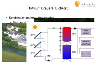
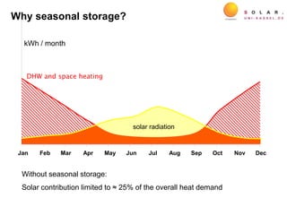
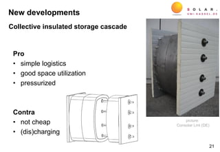
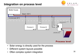
Angebot & Bedarf
2.
8
5.
5
6.
6
7.
4
8.
1
8.
8
9.
6
10
.3
11
.1
11
.8
12
.5
13
.3
14
.0
14
.7
15
.5
16
.2
17
.0
17
.7
18
.4
19
.2
19
.9
22
.4
Zeit [h] ->
Angebot 5m² Bedarfsdeckung 90%
Angebot & Bedarf
2.
8
5.
5
6.
6
7.
4
8.
1
8.
8
9.
6
10
.3
11
.1
11
.8
12
.5
13
.3
14
.0
14
.7
15
.5
16
.2
17
.0
17
.7
18
.4
19
.2
19
.9
22
.4
Zeit [h] ->
Angebot 5m² Bedarfsdeckung 90%
120 24
Tageszeit [h]
Leistung[kW]
15
20
12
6
3
power(kW)
time of day (h)
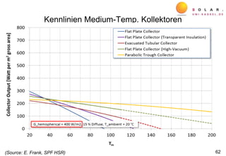
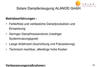
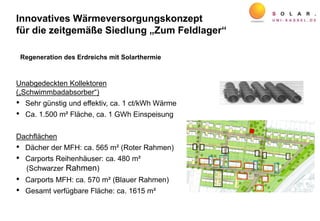
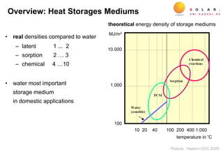
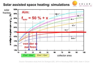
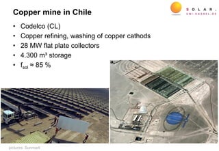
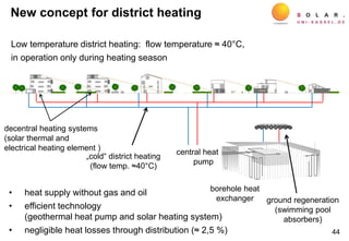
Solar irradiance on a 5 m² collector area
and domestic hot water demand of a single family dwelling
picture: H. Drück, Stuttgart Univ.
Why diurnal storage?](https://image.slidesharecdn.com/141007vajenedinburghfinal-150129140455-conversion-gate02/85/Storages-for-solar-heating-systems-at-domestic-community-and-industrial-scales-Klaus-Vajen-3-320.jpg)

![-0.625
-0.500
-0.375
-0.250
-0.125
0.000
0.125
0.250
0.375
0.500
0.625
0.750
0.875
1.000
-125
-100
-75
-50
-25
0
25
50
75
100
125
150
175
200
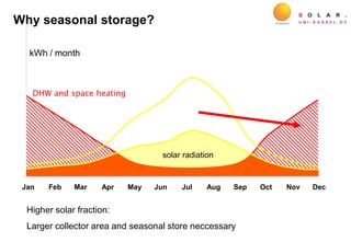
Nov Dez Jan Feb Mrz Apr Mai Jun Jul Aug Sep Okt
relativerWärmeinhaltSpeicher[-]
Wärmemenge[kWh]
Solar Pos. Zusatzwärm WW-Verbrau Gesamt-NUT Wärmeverl. Rel. WärmeQsol Qzusatz QTW QHK QSp,verl qSp,relativ
heating period 2011/2012 HP 2012summer period 2012
Qaux QDHW QSH Qsto,loss qsto,relQsol
OctMayDec
Heatconsumptionperday[kWh]
Relativeheatcontentofstore[-]
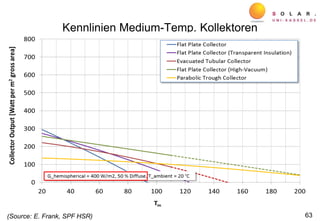
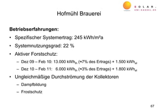
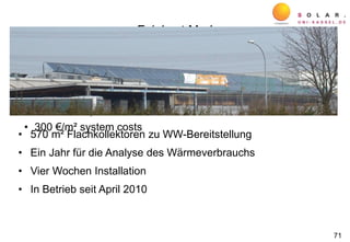
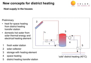
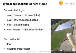
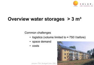
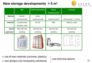
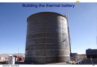
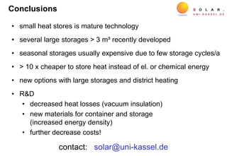
Storage management
source: H. Drück, Stuttgart Univ., 2013
House: 550 m², Collector 62 m² @ 44°, Storage: 15 m³](https://image.slidesharecdn.com/141007vajenedinburghfinal-150129140455-conversion-gate02/85/Storages-for-solar-heating-systems-at-domestic-community-and-industrial-scales-Klaus-Vajen-27-320.jpg)
![-0.625
-0.500
-0.375
-0.250
-0.125
0.000
0.125
0.250
0.375
0.500
0.625
0.750
0.875
1.000
-125
-100
-75
-50
-25
0
25
50
75
100
125
150
175
200
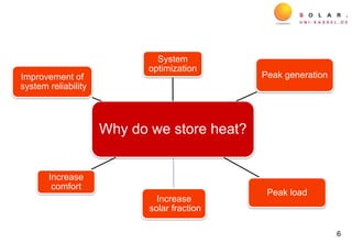
Nov Dez Jan Feb Mrz Apr Mai Jun Jul Aug Sep Okt
relativerWärmeinhaltSpeicher[-]
Wärmemenge[kWh]
Solar Pos. Zusatzwärm WW-Verbrau Gesamt-NUT Wärmeverl. Rel. WärmeQsol Qzusatz QTW QHK QSp,verl qSp,relativ
heating period 2011/2012 HP 2012summer period 2012
Qaux QDHW QSH Qsto,loss qsto,relQsol
OctMayDec
Heatconsumptionperday[kWh]
Relativeheatcontentofstore[-]
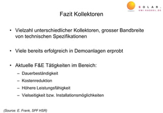
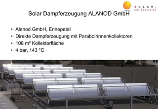
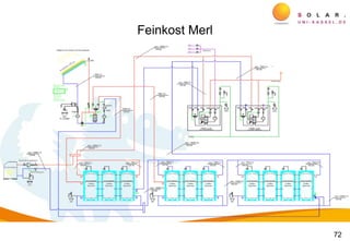
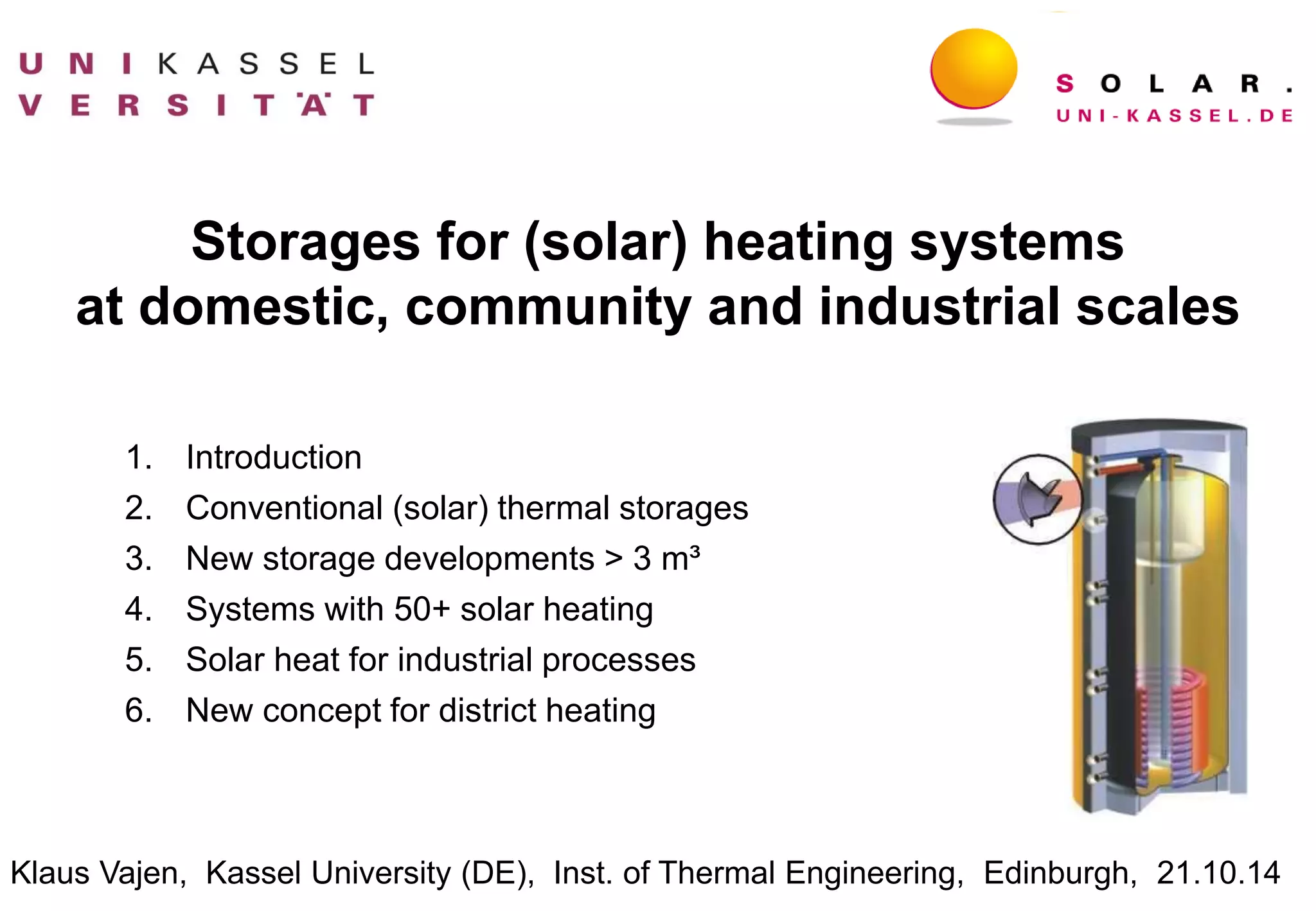
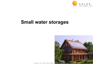
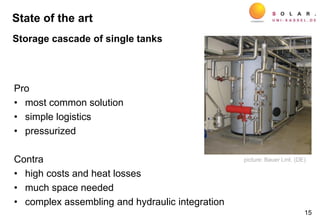
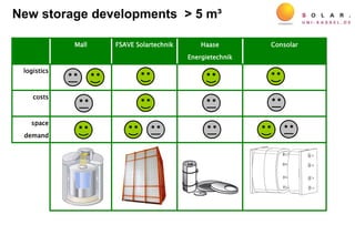
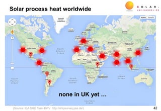
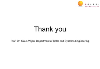
P1 P2 P3 P4
phase 1: storage discharching
Phase 2: auxiliary heating
Phase 3: storage charching
Phase 4: excess of solar energy
Storage management
source: H. Drück, Stuttgart Univ., 2013](https://image.slidesharecdn.com/141007vajenedinburghfinal-150129140455-conversion-gate02/85/Storages-for-solar-heating-systems-at-domestic-community-and-industrial-scales-Klaus-Vajen-28-320.jpg)
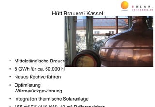
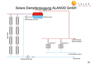
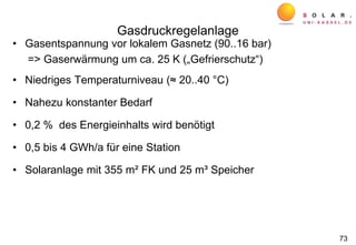
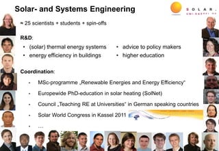
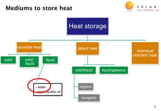
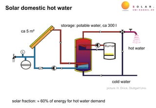
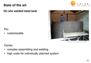
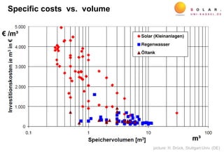
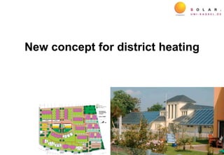
![Processes utilized as storages
Possibility to increase system performance and reduce system costs
• reduction of stagnation during off-times
• reduced volume of solar buffer tank
• …
Feasibility depends on
• maximum temperature
• sedimentation or cleaning periods
• …
38[www.gz-online.de]
[KRONES]
Electro plating baths
Tunnel pasteurizer for beverages](https://image.slidesharecdn.com/141007vajenedinburghfinal-150129140455-conversion-gate02/85/Storages-for-solar-heating-systems-at-domestic-community-and-industrial-scales-Klaus-Vajen-38-320.jpg)

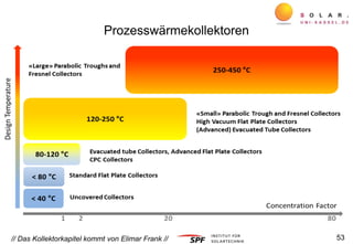
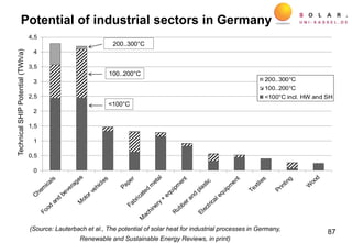
![Potential in European countries
48
0
1
2
3
4
5
0
4
8
12
16
Germany Italy Spain Austria Portugal Netherlands
SHIPpotential/industrialheatdemand[%]
TechnicalSHIPpotential[TWhperyear]
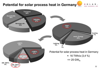
SHIP Potential for EU 25 ≈ 70 TWh/a =>
approx. 110 GWth
(Source: IEA SHC Task 33/IV)](https://image.slidesharecdn.com/141007vajenedinburghfinal-150129140455-conversion-gate02/85/Storages-for-solar-heating-systems-at-domestic-community-and-industrial-scales-Klaus-Vajen-48-320.jpg)