1. ProdukteD-HG400
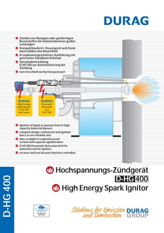
■ Ignition of liquid or gaseous fuels in high-
capacity industrial burners
■ Compact design: control unit and ignition
lance as one modular unit
■ Also available in explosion-proof
version with separate ignition lance
■ D-VE 500 Pneumatic Retraction Unit for
automatic burner ignition
■ no wear and tear because thyristor controlled
■ Zünden von flüssigen oder gasförmigen
Brennstoffen für Industriebrenner großer
Leistungen
■ Kompaktbauform: Steuergerät und Zünd-
lanze bilden eine Baueinheit
■ In explosionsgeschützter Ausführung mit
getrennter Zündlanze lieferbar
■ Vorschubeinrichtung
D-VE 500 zur Automatisierung der
Zündung
■ kein Verschleiß da thyristorgesteuert
D-HG400
Hochspannungs-Zündgerät
High Energy Spark Ignitor
D-HG 400
2. Hochenergie-Zündgerät D-HG 400
■ Anwendung
Das DURAG-Hochenergie-Zündgerät zündet Öl- und Gasbren-
ner beliebiger Leistungen. In der Standardausführung sind die
Zündlanze und das Steuergerät zu einer kompakten Einheit zusam-
mengefasst.
Abhängig von der Ausführung des Zündgerätes lässt sich die
Zündung über einen Drucktaster am Gerät oder automatisch durch
Anlegen der Betriebsspannung auslösen.
Nach dem Zünden muss die Zündspitze zum Schutz vor thermi-
scher Überlastung aus dem Flammenbereich gezogen werden. Dies
kann im Handbetrieb oder im Automatikbetrieb durch eine DURAG
Vorschubeinrichtung D-VE500 erfolgen. Bei speziellen Brennerkon-
struktionen (z.B. Fackelanlagen) kann auf ein Zurückziehen verzich-
tetwerden,wenndieFlammenachdemZündensoweitabwandert,
dass die thermische Belastung innerhalb der zulässigen Betriebs-
temperatur bleibt.
Die Zündlanzenlänge wird nach den Erfordernissen der Anlage
gefertigt.
■ Funktion
Im Zündgerät wird in einem Hochspannungskondensator eine
Energie von 4,5 Ws eingespeichert. Mit einem verschleißfreien
Schaltelement wird diese Energie über eine Bogenentladung (Fun-
ke) an der Zündspitze freigesetzt. Diese Entladung zündet den
Brennstoff.
Zur sicheren Zündung in der Startphase liefert das Gerät 60 s
lang 20 Zündfunken/s und schaltet dann auf 5 Zündfunken/s
zurück.
Es erfolgt eine Zündrückmeldung über die rote Leuchtdiode
oderdenpotentialfreienKontaktausgang,wenneinekorrekteEntla-
dung des Hochspannungskondensators festgestellt wurde.
■ Anwendung D-VE 500
DassichereZündeneinesBrennersmitdemD-HG400setzteine
genaue Positionierung der Zündspitze am Brennstoff-Luftgemisch,
bzw. ins Brennstoff-Luftgemisch, voraus. Die Temperaturen im Be-
reich der optimalen Zündzone sind jedoch in den meisten Fällen
währendderBetriebszeitdesBrennersvielzuhoch,sodassesander
■ Typen-Übersicht
■ D-HG400-50: für Betrieb in automatischen Anlagen
■ D-HG400-51: für Betrieb mit manueller Zündauslösung über
eingebaute Drucktaste
■ D-HG400-53: Für den Betrieb in explosionsgefährdeten An-
lagen, gekapselt in einem Ex-Gehäuse nach Zündklasse
EEx de IIC T6, mit PTB-Zertifikat Nr. 94.C.1065
■ D-HG400-56: für Betrieb mit manueller Zündauslösung über
eingebauten Rastenschalter
■ D-HG400-65: Anschluss der Zündlanze über Kabel
■ D-HG 400-72: Für den Betrieb in explosionsgefährdeten An-
lagen, gekapselt in einem Ex-Gehäuse nach Zündklasse
EEx d IIC T6, mit INIEX Zertifikat Nr. 83.103.251.
■ D-HG 400-73: Für den Betrieb in explosionsgefährdeten An-
lagen, gekapselt in einem Ex-Gehäuse nach Zündklasse
EEx d IIB T6, mit ISSeP-Zertifikat Nr. 95D.103.1222
■ D-HG 400-80: Wie D-HG 400-51 als portables Zündgerät mit
integrierter Zündlanze, Handgriff und Start-Taster
■ D-HG 400-81: Tragbares Batterie mit Schulterriemen und mit
integriertem Ladegerät, als Versorgung für das Zündgerät
D-HG 400-80
■ D-VE 500: Pneumatische Vorschubeinrichtung für Zündlanzen
Zündspitze zu Schäden führen würde.
Zur Automatisierung des Zündvorganges ist also eine Vorschu-
beinrichtung einzusetzen. Sie übernimmt die Aufgabe, die Zünd-
spitze genau in den Zündbereich des Brenners hineinzufahren und
nach erfolgter Zündung wieder aus dem Flammenbereich heraus-
zuziehen.
Die pneumatische Vorschubeinrichtung der Serie D-VE 500 ist
speziell für diese Aufgabe entwickelt worden. Sie ist sehr robust auf-
gebaut und lässt sich einfach und platzsparend an nahezu jeden
Brenner montieren. Sie ist mit einem Hub von 300, 400, 500 und 600
mm lieferbar (Standardtyp 300 mm Hub).
Die Vorschubeinrichtung ist mit einem Magnetventil ausgestat-
tet, das durch Anlegen der Betriebsspannung die Umschaltung der
Verfahrrichtung steuert. Der Kolben der Vorschubeinrichtung ist mit
einem Permanentmagneten versehen, der mit den entsprechenden
Schaltern eine oder beide Endlagen anzeigt.
Hochenergie-Zünd-
gerät mit Zündlanze
High Energy Spark
Ignitor with Ignition
Lance
3. D-HG 400 High Energy Spark Ignitor
■ Application
The DURAG High Energy Spark Ignitor ignites oil and gas
burners of any capacity. In its standard version, the ignition lance
and the control unit form a compact module.
Depending on the ignition device model, ignition can be
triggered either through a push button or automatically by feeding
the supply voltage.
After fuel ignition the igniter tip must be retracted from the
flame area as a protection against heat overload. This can be done
manually or automatically, in the latter case by way of a DURAG
D-VE500 Pneumatic Retraction Unit. With special burner types (e.g.
torch systems), no retraction is required if after ignition the flame
wanders so far off that the thermal load stays within the permissible
working temperature.
The length of the ignition lance is manufactured to suit the
furnace plant's requirements.
■ Functional Description
Insidetheignitionunit,theenergyequivalentof4.5Wsisloaded
into a high-voltage capacitor. With the help of a wear proof
switching element, this energy is released to the ignition tip, where
through an arc discharge it is converted to heat. It is this arc
discharge that ignites the fuel.
For ensured ignition in the start-up phase the unit generates 20
ignition sparks/s during 60s and ensuingly reduces it to 5 ignition
sparks/s.
When the ignition device is switched to the supply voltage, the
ignition function message will be issued by way of the built-in LED
and through the ignition signal relay’s output contact.
■ Application D-VE 500
The exact positioning of the ignition tip at the fuel-air mix is
crucial for the safe ignition of a burner with the D-HG 400. However,
in most cases the temperature in the region of the optimal ignition
zone is much too high, so that damage would occur to the ignition
tip.
A pneumatic retraction unit is employed which automates the
ignition process. This unit ensures that the ignition tip is inserted
■■ Unit Type Survey
■ D-HG400-50: For use in automatic plants
■ D-HG400-51: For use with manual ignition triggering
through an integrated push button
■ D-HG400-53: For use in hazardous areas, with flameproof
enclosure executed as EEx de IIC T6, with PTB-Certificate No.
94.C.1065
■ D-HG400-56: For use with manual ignition triggering
through built-in switch
■ D-HG400-65: Ignition lance connected by cable
■ D-HG 400-72: For use in hazardous areas, with flameproof
enclosure executed as EEx d IIC T6, with INIEX-Certificate No.
83.103.251.
■ D-HG 400-73: For use in hazardous areas, with flameproof
enclosure executed as EEx d IIB T6, with ISSeP- Certificate No.
95D.103.1222
■ D-HG 400-80: Same as D-HG 400-51, but executed as porta-
ble ignitor with integrated ignition lance and push button for
"START".
■ D-HG 400-81: Portable battery pack with shoulder strap and
integrated battery charger, to supply the D-HG 400-80 ignitor
■ D-VE 500: Pneumatic retraction unit for ignition lances
exactly into the ignition zone of the burner and after successful
ignition, retracted from the flame area.
The pneumatic retraction unit D-VE 500 has been specially
developed for this purpose. It has a robust construction and is easily
mounted onto almost any burner. Delivery is available with a stroke
lengthof300,400,500and600 mm(Thestandardversionis300mm
stroke length).
The retraction unit is fitted with a solenoid valve which controls
theswitchingofthedirectionofmovement.Thevalveisactivatedby
the operating current. The piston of the retraction unit is fitted with
a permanent magnet which shows one or both end limits with
respective switching.
Anwendungsbeispiel:
Claus-Anlage
Claus Plant Application
Example
4. D-HG400
■ Technische Daten D-HG 400
Netzspannung . . . . . . . . . . . . . . . . . 115/230V AC +10% / -15%
Frequenz . . . . . . . . . . . . . . . . . . . . . . . 42 - 60 Hz
Auch lieferbar für . . . . . . . . . . . . . . . 24V / 48V DC
Leistungsaufnahme . . . . . . . . . . . . 220VA
Zündenergie (je Funke) . . . . . . . . . 4,5Ws
Zündspannung . . . . . . . . . . . . . . . . 1500V
Zündfrequenz . . . . . . . . . . . . . . . . . . Einschaltphase (60 s):
20 Funken/s
Restzeit: 5 Funken/s
Max. Einschaltdauer . . . . . . . . . . . . 300 s ED 50%
Lebensdauer der Zündspitze . . . 106
Zündfunken
= 14 h bei 20 Funken/s
= 56 h bei 5 Funken/s
Zulässige Umgebungstemperaturen:
Steuergerät . . . . . . . . . . . . . . . . . . . . - 20°C / +60°C
Zündspitze . . . . . . . . . . . . . . . . . . . . . 600°C, kurzzeitig 800°C
Zündrückmeldung . . . . . . . . . . . . . Potentialfreier Umschalt-
kontakt nach VDE0110
Gr. C250V AC
Schaltvermögen . . . . . . . . . . . . . . . 250V AC - 4 A/200VA
Gewichte:
Steuergerät ohne Lanze . . . . . . . . 4,3kg
D-HG 400-53. . . . . . . . . . . . . . . . . . . . 40kg
D-HG 400-72. . . . . . . . . . . . . . . . . . . . 13kg
D-HG 400-73 . . . . . . . . . . . . . . . . . . . 23kg
D-HG 400-81. . . . . . . . . . . . . . . . . . . . 11 kg
Zündlanze ohne
Verstärkungsrohr . . . . . . . . . . . . . . . 1,6 kg/m
Schutzart DIN EN 60529. . . . . . . . . IP55
■■ Technische Daten D-VE 500
max. zul. Betriebsdruck . . . . . . . . . 10 bar
Luftverbrauch je Hub . . . . . . . . . . . 0,065 I/cm bei 2 bar Betriebsdruck
0,190 l/cm bei 6 bar
0,320 I/cm bei 10 bar
zul. Umgebungstemperatur. . . . -5 bis +50°C
Standard-Hublänge. . . . . . . . . . . . . 300 mm
Sonder-Hublängen . . . . . . . . . . . . . 400, 500, 600 mm
Schubkraft bei 6 bar . . . . . . . . . . . . 1870 N
Rückzugkraft bei 6 bar . . . . . . . . . . 1682 N
Gewicht komplett bei
300 /400 / 500 / 600 mm Hub . . . 9,1 / 10,7 / 12,3 / 13,9 kg
elektr. Ansteuerung. . . . . . . . . . . . . 24/48V DC oder 115/230 V AC
Schutzart EN 60529 . . . . . . . . . . . . . IP54
■ Technical Data of D-HG 400
Power supply . . . . . . . . . . . . . . . . . . 115/230 V AC +10% / -15%
Mains frequency . . . . . . . . . . . . . . . 42 - 60 Hz
Also available are units for . . . . . . 24 / 48V DC
Power consumption . . . . . . . . . . . . 220VA
Ignition energy (per spark). . . . . . 4.5Ws
Ignition voltage . . . . . . . . . . . . . . . . 1500V
Ignition frequency . . . . . . . . . . . . . . Switching phase (60 s):
20 sparks/s
Residual time: 5 sparks/s
Max. duty cycle . . . . . . . . . . . . . . . . . 300 s IU 50 %
Ignition tip service life . . . . . . . . . . 106
ignition sparks
= 14h at 20 sparks/s
= 56h at 5 sparks/s
Permissible ambient temperatures:
Control unit . . . . . . . . . . . . . . . . . . . . - 20°C / +60°C
Ignition tip . . . . . . . . . . . . . . . . . . . . . 600°C, 800°C peak
Ignition Indication . . . . . . . . . . . . . . zero potential change-over
contact to VDE0110
Gr. C 250V AC
Switching capacity . . . . . . . . . . . . . 250VAC- 4 A /200VA
Weights:
Control unit without lance . . . . . . 4,3kg
D-HG 400-53. . . . . . . . . . . . . . . . . . . . 40kg
D-HG 400-72. . . . . . . . . . . . . . . . . . . . 13kg
D-HG 400-73 . . . . . . . . . . . . . . . . . . . 23kg
D-HG 400-81. . . . . . . . . . . . . . . . . . . . 11 kg
Ignition lance without
reinforcing tube . . . . . . . . . . . . . . . . 1.6 kg/m
Protection DIN EN 60529. . . . . . . . IP55
■■ Technical Data of D-VE 500
max. permissible operating pressure 10 bar
Air consumption per stroke . . . . . 0,065 l/cm at 2 bar
operating pressure
0,190 l/cm at 6 bar
0,320 l/cm at 10 bar
Permissible ambient temp.. . . . . . -5 to +50°C
Standard stroke length . . . . . . . . . 300 mm
Special stroke lengths. . . . . . . . . . . 400, 500, 600 mm
Transverse force at 6 bar . . . . . . . . 1870 N
Return force at 6 bar . . . . . . . . . . . . 1682 N
Total weight for
300 / 400 /500 / 600 mm stroke . 9,1 / 10,7 / 12,3 / 13,9 kg
Electrical control. . . . . . . . . . . . . . . . 224/48 V DC or 115/230 V AC
Protection DIN EN 60529. . . . . . . . IP54 D-HG400
Ausführliche Gerätebeschreibungen mit technischen Daten, Einstel-
lanweisungen, Abmessungen und Anschlussplänen stehen auf An-
forderung zur Verfügung.
Extensive descriptions of these units with specifications, setting in-
structions, dimensions and connection plans are available upon re-
quest.
www.durag.de 03/2002 - All specifications subject to change without notice
DURAG Industrie Elektronik
GmbH & Co KG
Kollaustr. 105
D-22453 Hamburg, Germany
Tel. +49 40 55 42 18-0
Fax +49 40 58 41 54
Georg Hegwein
GmbH & Co. KG
Am Boschwerk 7
D-70469 Stuttgart, Germany
Tel. +49 711 13 57 88-0
Fax+49 711 13 57 88-5
VEREWA Umwelt- und
Prozessmesstechnik GmbH
Kollaustr. 105
D-22453 Hamburg, Germany
Tel. +49 40 55 42 18-0
Fax +49 40 58 41 54
ORFEUS Combustion
Engineering GmbH
An der Pönt 53a
D-40885 Ratingen, Germany
Tel. +49 2102 9974-0
Fax +49 2102 9974-41
DURAG, Inc.
Southridge Business Center
1355 Mendota Heights Road #200
Mendota Heights,
Minnesota 55120, USA
Tel. +1 651 451-1710
Fax +1 651 457-7684