Downloaden Sie, um offline zu lesen


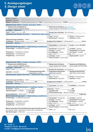
![Nr. 13.03 -7
Telefax 0 72 61 -92 63-33
e-mail: info@grob-antriebstechnik.de
5
1.1.1 Auswahlkriterien der Stellantriebe
1.1.1 Linear actuator selection criteria
Baugröße
Type
Bestellcode
Order code
max. Hublast
max. lifting capacity
Geschwindigkeit
Speed
HUB
Stroke
[N] [mm/sec] [mm]
GL60D
7-GL60D-0050-05-0 6000 5 50
7-GL60D-0100-05-0 6000 5 100
7-GL60D-0150-05-0 6000 5 150
7-GL60D-0200-05-0 6000 5 200
7-GL60D-0250-05-0 5400 5 250
7-GL60D-0300-05-0 3900 5 300
7-GL60D-0350-05-0 2900 5 350
7-GL60D-0400-05-0 2300 5 400
7-GL60D-0450-05-0 1900 5 450
7-GL60D-0500-05-0 1500 5 500
7-GL60D-0600-05-0 1100 5 600
7-GL60D-0700-05-0 790 5 700
7-GL60D-0800-05-0 610 5 800
7-GL60D-0900-05-0 490 5 900
7-GL60D-1000-05-0 400 5 1000
7-GL60D-0050-20-0 2000 20 50
7-GL60D-0100-20-0 2000 20 100
7-GL60D-0150-20-0 2000 20 150
7-GL60D-0200-20-0 2000 20 200
7-GL60D-0250-20-0 1800 20 250
7-GL60D-0300-20-0 1200 20 300
7-GL60D-0350-20-0 966 20 350
7-GL60D-0400-20-0 766 20 400
7-GL60D-0450-20-0 630 20 450
7-GL60D-0500-20-0 506 20 500
7-GL60D-0600-20-0 366 20 600
7-GL60D-0700-20-0 263 20 700
7-GL60D-0800-20-0 202 20 800
7-GL60D-0900-20-0 163 20 900
7-GL60D-1000-20-0 133 20 1000
1.1.1.1 Typenübersicht
1.1.1.1 Type overview](https://image.slidesharecdn.com/7st13037-151117133236-lva1-app6892/85/Stellantrieb-de-en-5-320.jpg)
![6
Nr. 13.03 -7
Telefax 0 72 61 -92 63-33
e-mail: info@grob-antriebstechnik.de
1. Artikelgruppe
7
2. Baugröße
GL60D
3. Hub
in mm angegeben (4-stellig)
4. Geschwindigkeit
05 = 5 mm/sec
20 = 20 mm/sec
5. Ausführungen
0 = Standard
1. Article category
7
2. Type
GL60D
3. Stroke
Please state in mm (4 digits)
4. Speed
05 = 5 mm/sec
20 = 20 mm/sec
5. Version
0 = Standard
1.1.1.2 Bestellcode
1.1.1.2 Order code
7 GL60D 0050 05 0
1. 2. 3. 4. 5.
Betriebsspannung
Operating voltage
[V/DC] 24
Hublast
Lifting capacity
[N] 6000
Geschwindigkeit
Speed
[mm/sec.] 5 (6000N)
[mm/sec.] 20 (2000N)
HUB
Stroke
[mm] 50 ... 1000
Länge eingefahren
Length retracted
[mm] HUB + 175
Statische Last
Static load
[N] 8000
Einschaltdauer
Duty cycle
[%] 10
Überlastschutz
Overload protection
Kontrollbox
Control Box
Schutzart
Protection class
IP43
1.1.2 Stellantrieb GL60D-Serie
1.1.2 Linear Actuartor GL60D Series](https://image.slidesharecdn.com/7st13037-151117133236-lva1-app6892/85/Stellantrieb-de-en-6-320.jpg)

![8
Nr. 13.03 -7
Telefax 0 72 61 -92 63-33
e-mail: info@grob-antriebstechnik.de
1.1.3 Zubehör
1.1.3 Accessories
Baugröße
Type
Bestellcode
Order code
Eingangsspannung
Input voltage Abgänge
Output
[V]
GLB86
GLB24
7-GLB86-24-010 1x230 AC 1 1
7-GLB86-24-011 1x110 AC 1 1
7-GLB86-24-020 1x230 AC 2 2
7-GLB86-24-021 1x110 AC 2 2
7-GLB86-24-040 1x230 AC 4 4
7-GLB86-24-041 1x110 AC 4 4
7-GLB24-24-010 1x24 DC 1 1
7-GLB24-24-020 1x24 DC 2 2
7-GLB24-24-040 1x24 DC 4 4
7-GLB86-... 7-GLB24-...
Betriebsspannung
Operating voltage
[V/AC]
110 oder 230
110 or 230
24
Ausgangsspannung
Output voltage
[V/DC] 24 (86VA) 24 (86VA)
Einschaltdauer
Duty cycle
[%] 10 - 50 10 - 50
Verbindung mit 1-4 Linearantrieben und Handbedienung möglich.
Connection of 1-4 linear actuators and hand operater possible.
1.1.3.1 Kontrollbox
1.1.3.1 Control box](https://image.slidesharecdn.com/7st13037-151117133236-lva1-app6892/85/Stellantrieb-de-en-8-320.jpg)


![Nr. 13.03 -7
Telefax 0 72 61 -92 63-33
e-mail: info@grob-antriebstechnik.de
17
146
56
130
25
152
142
26
1.2.2 Stellantrieb FD-Serie
1.2.2 Linear actuator FD series
Baugröße
Type
Bestellcode
Order code
Bezeichnung
Description
HUB
Stroke
Motor
Kontrollbox
Control Box
Handbedienung
Hand Operator
[mm] [V/DC] [V/AC]
7-FD6
7-FD-Synchron-0050-00
Synchronlauf Set 2 Stellantriebe
Synchronous running (with
feedback) set 2 actuators
50 24 230 HDU2
7-FD-Synchron-0100-00 100 24 230 HDU2
7-FD-Synchron-0150-00 150 24 230 HDU2
7-FD-Synchron-0200-00 200 24 230 HDU2
7-FD-Synchron-0250-00 250 24 230 HDU2
7-FD-Synchron-0300-00 300 24 230 HDU2
7-FD-Synchron-0050-01 50 24 230 HD2
7-FD-Synchron-0100-01 100 24 230 HD2
7-FD-Synchron-0150-01 150 24 230 HD2
7-FD-Synchron-0200-01 200 24 230 HD2
7-FD-Synchron-0250-01 250 24 230 HD2
7-FD-Synchron-0300-01 300 24 230 HD2
Handbedienung HDU2
Hand Operator HDU2
Handbedienung HD2
Hand Operator HD2](https://image.slidesharecdn.com/7st13037-151117133236-lva1-app6892/85/Stellantrieb-de-en-17-320.jpg)

![Nr. 13.03 -7
Telefax 0 72 61 -92 63-33
e-mail: info@grob-antriebstechnik.de
19
2.1.1 Auswahlkriterien der Stellantriebe
2.1.1 Linear actuator selection criteria
Baugröße
Type
Spindel
Spindle
Übersetzung
Ratio
Geschwindigkeit
Speed
dyn. Belastung
dynamic load
[mm/sec] [N]
7-SAIP65 TR 16x4
4:1 So 50 1500
5:1 So 40 1700
6,5:1 So 30,77 2000
10:1 So 20 2800
15:1 Ss 13 3900
20:1 Ss 10 4500
30:1 Sd 6,67 6000
40:1 Sd 5 6000
50:1 Sd 4 6000
7-SAIP65 KGT 1602
4:1 So 25 1500
5:1 So 20 1700
6,5:1 So 15,38 2000
10:1 So 10 2500
15:1 So 6,67 2500
20:1 So 5 2500
30:1 So 3,33 2500
40:1 So 2,5 2500
50:1 So 2 2500
So = keine Selbsthemmung So = no self-locking
Ss = statische Selbsthemmung Ss = static self-locking
Sd = dynamische Selbsthemmung Sd = dynamic self-locking
2.1.1.1 Typenübersicht
2.1.1.1 Type overview
Hub
Stroke
Hublast
Lifting force
[mm] [N]
100 8000
200 8000
300 8000
400 6780
500 4450
600 3150
700 2350
800 1800](https://image.slidesharecdn.com/7st13037-151117133236-lva1-app6892/85/Stellantrieb-de-en-19-320.jpg)
![20
Nr. 13.03 -7
Telefax 0 72 61 -92 63-33
e-mail: info@grob-antriebstechnik.de
2.1.1.1 Typenübersicht
2.1.1.1 Type overview
Drehstrommotor 3 Phase motor
M056 M063
Betriebsspannung
Operating voltage
[V] 230 / 400 230 / 400
Frequenz
Frequency
[Hz] 50 50
Drehzahl
Speed
[1/min] 3000 3000
Leistung
Power
[kW] 0,09 0,18
Schutzart
Protection class
IP65 IP65
Bauform
Version
B14 B14
DC-Motor
GR63x55
Betriebsspannung
Operating voltage
[V/DC] 24
Strom
Current
[A] ANenn = 4,9
Drehzahl
Speed
[1/min] 3350
Leistung
Power
[kW] 0,09
Schutzart
Protection class
IP65](https://image.slidesharecdn.com/7st13037-151117133236-lva1-app6892/85/Stellantrieb-de-en-20-320.jpg)

![22
Nr. 13.03 -7
Telefax 0 72 61 -92 63-33
e-mail: info@grob-antriebstechnik.de
60Ø
136
54
15
15
77
HUB+257
10
25Ø
HUB / Stroke
38Ø
121
10
94
2.1.2 Stellantriebe SAIP65-Serie
2.1.2 Linear actuator SAIP65 series
Durchmesser Kolbenstange
Diameter piston rod
[mm] 25
Durchmesser Führungsrohr
Diameter guide tube
[mm] 38
Motorleistung
Motor capacity
[W] 60...150
Andere Antriebe auf Anfrage Other types on request
Motorspannung
Motor voltage
[V]
DC12...DC24
AC230...240
Motordrehzahl
Motor Speed
[rpm] 3000
Belastung dynamisch max.
Dynamic load max
[N] 6000
Zugbelastung max.
Tensile load max
[N] 8000
Druckbelastung max. (abhängig vom Hub)
Compression load max (dependent on stroke)
[N] 8000
Endlagenschalter Limit switches
Magnetfeldsensoren Magnetic sensors](https://image.slidesharecdn.com/7st13037-151117133236-lva1-app6892/85/Stellantrieb-de-en-22-320.jpg)


![Nr. 13.03 -7
Telefax 0 72 61 -92 63-33
e-mail: info@grob-antriebstechnik.de
25
10
10
50Ø
S=400+HUB / Stroke
20Ø
20Ø
HUB / Stroke
S1=S+HUB / Stroke
10
10
2.2 Elektrozylinder EZ02
2.2 Electric Cylinder EZ02
max. dynamische Belastung:
max dynamic load:
[N] 2000
max. statische Belastung:
max static load:
[N] 5000
max. Geschwindigkeit belastet:
max speed at load:
[mm/sec] 5
Motorspannung:
Motor voltage:
[V/DC] 24
Umgebungstemperatur:
Ambient temperature:
[°C] -5 bis / to +40
Hub:
Stroke:
[mm] 100, 200, 300, 400, 500, 600, 700, 800
Einschaltdauer:
Duty cycle:
max. 10 % oder 2 Minuten Dauerbetrieb bei anschließend 18 Minuten Pause
max 10% or 2 minutes continuous use followed by 18 minutes interval
Geräuschpegel unbelastet:
Noise level at no load:
[dB] 48
Farbe:
Colour:
Silber
silver white
Elegantes kompaktes Design Elegant compact design
Einbaumaß (min.) 400 mm + Hub (+/- 2 mm) Assembly dimension (min.) 400 mm + stroke (+/- 2 mm)
Interne Endschalter (nicht verstellbar, nur interne Abschaltung) Built-in limit switches (not adjustable)
Standard Schutzclasse IP65 Standard protection class IP65
Baugröße
Type
Bestellcode
Order code
Bezeichnung
HUB
Stroke
[mm]
EZ02
81-000000001 EZ02-A/A/G-2000-05-0100 100
81-000000002 EZ02-A/A/G-2000-05-0200 200
81-000000003 EZ02-A/A/G-2000-05-0300 300
81-000000004 EZ02-A/A/G-2000-05-0400 400
81-000000005 EZ02-A/A/G-2000-05-0500 500
81-000000006 EZ02-A/A/G-2000-05-0600 600
81-000000007 EZ02-A/A/G-2000-05-0700 700
81-000000008 EZ02-A/A/G-2000-05-0800 800](https://image.slidesharecdn.com/7st13037-151117133236-lva1-app6892/85/Stellantrieb-de-en-25-320.jpg)


![Nr. 13.03 -7
Telefax 0 72 61 -92 63-33
e-mail: info@grob-antriebstechnik.de
29
2.3.1.2 Bestellcode
2.3.1.2 Order code
Baugröße
Type
Bestellcode
Order code
Übersetzung
Ratio
HUB
Stroke
Leistung Ausführung
Version
Motor Schutzart
Protection
class
Endschalter
Limit switch
[mm] [N] [V/DC]
7-LD3
7-LD3-0050-1-5-1-7 5:1 50
150
24 IP65
inkl.
Endschalter
(nur intern)
Integrated
limit switches
(for internal
use)
7-LD3-0100-1-5-1-7 5:1 100
7-LD3-0150-1-5-1-7 5:1 150
7-LD3-0200-1-5-1-7 5:1 200
7-LD3-0250-1-5-1-7 5:1 250
7-LD3-0300-1-5-1-7 5:1 300
7-LD3-0050-1-10-1-7 10:1 50
250
7-LD3-0100-1-10-1-7 10:1 100
7-LD3-0150-1-10-1-7 10:1 150
7-LD3-0200-1-10-1-7 10:1 200
7-LD3-0250-1-10-1-7 10:1 250
7-LD3-0300-1-10-1-7 10:1 300
7-LD3Q-0050-1-20-1-7 20:1 50
500
geräuscharme
Ausführung
low noise
version
7-LD3Q-0100-1-20-1-7 20:1 100
7-LD3Q-0150-1-20-1-7 20:1 150
7-LD3Q-0200-1-20-1-7 20:1 200
7-LD3Q-0250-1-20-1-7 20:1 250
7-LD3Q-0300-1-20-1-7 20:1 300
7-LD3Q-0050-1-30-1-7 30:1 50
700
7-LD3Q-0100-1-30-1-7 30:1 100
7-LD3Q-0150-1-30-1-7 30:1 150
7-LD3Q-0200-1-30-1-7 30:1 200
7-LD3Q-0250-1-30-1-7 30:1 250
7-LD3Q-0300-1-30-1-7 30:1 300
7-LD3-0050-1-40-1-7 40:1 50
1000
7-LD3-0100-1-40-1-7 40:1 100
7-LD3-0150-1-40-1-7 40:1 150
7-LD3-0200-1-40-1-7 40:1 200
7-LD3-0250-1-40-1-7 40:1 250
7-LD3-0300-1-40-1-7 40:1 300](https://image.slidesharecdn.com/7st13037-151117133236-lva1-app6892/85/Stellantrieb-de-en-29-320.jpg)


![Nr. 13.03 -7
Telefax 0 72 61 -92 63-33
e-mail: info@grob-antriebstechnik.de
35
A
Ø
13
Ø
13
50,8Ø
63,5Ø
112,594,928,1
151,6
77,1
163,1
HUB
2.4.1.2 Bestellcode
2.4.1.2 Order code
Baugröße
Type
Bestellcode
Order code
Überset-
zung
Ratio
HUB
Stroke
Motor Schutzart
Protection
class
Spindel
Spindle
[mm] [V/DC]
7-ID10S
7-ID10S-450-1-40-TR3+5
40:1
450
24 IP65
Trapezgewinde-
spindel
Trapezoidal spindle
inkl. Endschalter
+ Reed-Kontakte
7-ID10S-600-1-40-TR3+5 600
7-ID10S-900-1-40-TR3+5 900
7-ID10S-450-1-40-KG3+5 450 Kugelgewinde-
spindel
Ball screw spindle
Integrated
limit switches
+ Reed sensor
7-ID10S-600-1-40-KG3+5 600
7-ID10S-900-1-40-KG3+5 900
2.4.2 Stellantriebe ID10S-Serie
2.4.2 Linear actuator ID10S series
Hub
Stroke
450 600 900
Trapezgewindespindel TR
Trapezoidal spindle TR
A 764 917 1269
Kugelgewindespindel KGT
Ball screw spindle KGT
A 810 963 1315](https://image.slidesharecdn.com/7st13037-151117133236-lva1-app6892/85/Stellantrieb-de-en-35-320.jpg)
![36
Nr. 13.03 -7
Telefax 0 72 61 -92 63-33
e-mail: info@grob-antriebstechnik.de
2.4.3 Zubehör
2.4.3 Accessories
2.4.3.1 Kontrollbox
2.4.3.1 Control Box
2.4.3.2 Handbedienung
2.4.3.2 Hand Operator
Baugröße
Type
Bestellcode
Order code
Eingang
Input
Ausgang
Output
[V/DC] [V/DC]
7-CIS2 7-CIS2-24-24-02 24 24
für 2 Stellantriebe
for 2 Linear actuartors
Baugröße
Type
Bestellcode
Order code
7-HM6R 7-HM6R
für die Kontrollbox 7-CIS2
for the control box 7-CIS2](https://image.slidesharecdn.com/7st13037-151117133236-lva1-app6892/85/Stellantrieb-de-en-36-320.jpg)


![40
Nr. 13.03 -7
Telefax 0 72 61 -92 63-33
e-mail: info@grob-antriebstechnik.de
3.1 Auswahlkriterien der „EMH“
3.1 „EMH“ selection criteria
Baugröße
Grundmodell M100
Basic model M100 Type
F16 F20 F30 F40 F45 F50
max. statisch Belastung bei
TR-Spindel
[kN] 3 7,5 15 20 30 40 [kN] Max static load for Tr spindle
max. Zugkraft bei TR-Spindel [kN] 3 7,5 15 20 30 40 [kN] Max tensile force for TR spindle
Spindel TR 16x4 24x5 36x6 45x7 50x8 60x9 Spindle TR
Leerlaufdrehmoment [Nm] 0,38 0,52 1,6 1,9 2,1 2,1 [Nm] Idling torque N
Gewicht ohne Spindelhub [kg] 2 3,1 8 17,1 28,3 75 [kg] Weight without spindle
Gewicht pro 100 mm Hub [kg] 0,75 1,7 2,6 4,9 5,2 7,2 [kg] Weight per 100 mm stroke
3.1.1 Typenübersicht
3.1.1 Type overview](https://image.slidesharecdn.com/7st13037-151117133236-lva1-app6892/85/Stellantrieb-de-en-40-320.jpg)


![46
Nr. 13.03 -7
Telefax 0 72 61 -92 63-33
e-mail: info@grob-antriebstechnik.de
3.4 Anbauteile der „EMH“
3.4 Accessories of the „EMH“
Der Hubzylinder M205 wurde für hohe Belastung
bei hohen und niedrigen Verfahrgeschwin-dig-
keiten konstruiert.
Bestandteile
• Hubzylinder: M100 Grundmodell
• Befestigung: Kardanaufhängung
• Antrieb: Motor mit Getriebe
(opt. mit Bemse)
The M205 Actuator has been developed for han-
dling heavy loads and low and medium speeds.
Components
• Actuator: M100 Basic model
• Mounting: Cardan joints
• Drive: Geared motor
(brake may be required))
Index F20-M205 F30-M205 F40-M205 F45-M205 F50-M205
B 15 20 30 35 40
C 116 138 160 200 260
E 20 25 35 35 45
ØP f8 20 25 35 40 45
Index
Motordrehzahl
Motor speed Übersetzung
Ratio
[1/min]
M205
3000 2,5:1 3:1 4:1 5:1 6:1 10:1 20:1 50:1 100:1 250:1 500:1 1000:1
1500 2,5:1 3:1 4:1 5:1 6:1 10:1 20:1 50:1 100:1 250:1 500:1 1000:1
1000 2,5:1 3:1 4:1 5:1 6:1 10:1 20:1 50:1 100:1 250:1 500:1 1000:1
750 2,5:1 3:1 4:1 5:1 6:1 10:1 20:1 50:1 100:1 250:1 500:1 1000:1
3.4.1 M205 Getriebemotor Motoranordnung axial
3.4.1 M205 Geared motor, axial arrangement](https://image.slidesharecdn.com/7st13037-151117133236-lva1-app6892/85/Stellantrieb-de-en-46-320.jpg)


![58
Nr. 13.03 -7
Telefax 0 72 61 -92 63-33
e-mail: info@grob-antriebstechnik.de
Ph
i
= Spindelsteigung
= Übersetzung
= Spindle pitch
= Ratio
[mm]
Lh
Cdyn
Fdyn
n2
= Lebensdauer in Stunden
= dynamische Tragzahl
= Axialkraft dynamisch (= Hubkraft)
= Abtriebsdrehzahl (Spindel)
= Service life in hours
= Dynamic load rating
= Dynamic axial force (= lifting force)
= Output speed (spindle)
[h]
[kN]
[kN]
[min-1
]
Lebensdauer Service life
3.6 Kugelgewinde KGT
3.6 Ballscrew KGT
Grundmaße des M100 “Grundmodells” finden Sie
unter „M100 Grundmodell“ auf Seite 42!
Dimensional information for the M100 Basic model
can be found „M100 Basic model“ on page 42!
Index
KGT Spindel
KGT Spindle
max. statische Belastung
Max lifting force
max. Zugkraft
Max tensile force
Leerlaufdrehmoment
Idling torque
[kN] [kN] [Nm]
F16 KGS1605 5 5 0,25
F20
KGS2005 10 10 0,42
KGS2020 7,5 7,5 0,48
F30
KGS3205 20 20 1,3
KGS3210 25 25 1,3
KGS3220 20 20 1,3
KGS3240 10 10 1,3
F40
KGS4010 30 30 1,6
KGS4020 30 30 1,7
KGS4040 15 15 1,7
F45 KGS5010 50 50 1,7
F50 KGS6310 65 65 1,5](https://image.slidesharecdn.com/7st13037-151117133236-lva1-app6892/85/Stellantrieb-de-en-58-320.jpg)


![Nr. 13.03 -7
Telefax 0 72 61 -92 63-33
e-mail: info@grob-antriebstechnik.de
61
𝐝𝐝𝟐𝟐 = 𝐝𝐝 − 𝟎𝟎, 𝟓𝟓 ∙ 𝐏𝐏
d2
d
P
= Flankendurchmesser
= Nenndurchmesser des Gewindes
= Spindelsteigung eingängig / teilung
= Pitch diameter
= Nominal diameter of pitch
= Spindle single start pitch / lead
[mm]
[mm]
[mm]
Flankendurchmesser Pitch diameter
v
n1
Ph
i
= Hubgeschwindigkeit
= Antriebsdrehzahl
= Spindelsteigung
= Übersetzung
= Lifting speed
= Input speed
= Spindle pitch
= Ratio
[mm/min]
[min-1
]
[mm]
Hubgeschwindigkeit Lifting speed
Ph
nG
P
= Spindelsteigung
= Gangzahl
= Spindelsteigung eingängig / teilung
= Spindle pitch
= Number of threads
= Spindle single start pitch / lead
[mm]
[mm]
Spindelsteigung Spindle pitch
4. Berechnung
4. Calculation](https://image.slidesharecdn.com/7st13037-151117133236-lva1-app6892/85/Stellantrieb-de-en-61-320.jpg)
![62
Nr. 13.03 -7
Telefax 0 72 61 -92 63-33
e-mail: info@grob-antriebstechnik.de
ED
HUB
As
v
= Einschaltdauer
= Hubweg
= Anzahl der Lastspiele
(Auf- und Abbewegung)
z.B. 15 mal Spindel aus- und eingefahren
sind 30 Lastspiele
= Hubgeschwindigkeit
= Duty cycle
= Length of stroke
= Number of load cycles
(up- and down movement)
15 times in and out movement of the
spindle equals 30 double strokes
= Lifting speed
[%]
[mm]
[m/min]
Einschaltdauer bezogen auf 1 Stunde Duty cycle based on 1 hour
HU
Ph
i
= Hub / Umdrehung
= Spindelsteigung
= Übersetzung
= Stroke / Revolution
= Spindle pitch
= Ratio
[mm]
[mm]
Hub / Umdrehung Stroke / Revolution
Lh
Cdyn
Fdyn
n2
= Lebensdauer in Stunden
= dynamische Tragzahl
= Axialkraft dynamisch (= Hubkraft)
= Abtriebsdrehzahl (Spindel)
= Service life in hours
= Dynamic load rating
= Dynamic axial force (= lifting force)
= Output speed (spindle)
[h]
[kN]
[kN]
[min-1
]
Lebensdauer Service life
4. Berechnung
4. Calculation](https://image.slidesharecdn.com/7st13037-151117133236-lva1-app6892/85/Stellantrieb-de-en-62-320.jpg)
![Nr. 13.03 -7
Telefax 0 72 61 -92 63-33
e-mail: info@grob-antriebstechnik.de
63
M1
P
n1
= Antriebsdrehmoment
= Leistung
= Antriebsdrehzahl
= Input torque
= Power
= Input speed
[Nm]
[kW]
[min-1
]
Antriebsdrehmoment Input torque
M
Fdyn
ηH
Ph
i
ML
= Drehmoment pro Getriebe
= Axialkraft dynamisch (= Hubkraft)
= Wirkungsgrad Hubgetriebe
= Spindelsteigung
= Übersetzung
= Leerlaufdrehmoment
= Torque per screw jack
= Dynamic axial force (= lifting force)
= Screw jack efficiency
= Spindle pitch
= Ratio
= Idling torque
[Nm]
[kN]
[mm]
[Nm]
Drehmoment pro Getriebe Torque per screw jack
n2
n1
i
= Abtriebsdrehzahl (Spindel)
= Antriebsdrehzahl (Schneckenwelle)
= Übersetzung
= Output speed (spindle)
= Input speed (worm shaft)
= Ratio
[min-1
]
[min-1
]
Abtriebsdrehzahl (Spindel) Output speed (spindle)
4. Berechnung
4. Calculation](https://image.slidesharecdn.com/7st13037-151117133236-lva1-app6892/85/Stellantrieb-de-en-63-320.jpg)
![64
Nr. 13.03 -7
Telefax 0 72 61 -92 63-33
e-mail: info@grob-antriebstechnik.de
MSP
Fdyn
d2
φ
ϱ
= Spindeldrehmoment
= Axialkraft dynamisch (= Hubkraft)
= Flankendurchmesser
= Steigungswinkel
= Gleitreibungswinkel
= Spindle torque
= Dynamic axial force (= Lifting force)
= Pitch diameter
= Lead angle
= Dynamic friction angle
[Nm]
[kN]
[mm]
[°]
[°]
Spindeldrehmoment Spindle torque
φ
Ph
d2
= Steigungswinkel
= Spindelsteigung
= Flankendurchmesser
= Lead angle
= Spindle pitch
= Pitch diameter
[°]
[mm]
[mm]
Steigungswinkel Lead angle
Bei der Auslegung von Hebebühnen mit Gewin-
despindeln als Antriebsmittel gelten für den Ge-
windesteigungswinkel φ sowie eine eventuelle
Selbsthemmung des Gewindes folgende Regeln:
In the case of the design of lifting platforms with
threaded spindles as drive means, the following
rules apply to the thread lead angle φ and a pos-
sible self-locking of the thread:
- Selbsthemmung aus der Bewegung*
(dynamisch): φ < 2,4°
- Self-locking from movement*
(dynamic):
- Selbsthemmung im Stillstand*
(statisch): 2,4° < φ < 4,5°
- Self-locking at standstill*
(static):
- Keine Selbsthemmung: φ > 4,5° - No self-locking:
(* Voraussetzung ist ein vibrationsfreier Betrieb)
(* A prerequisite is a vibration-free operation)
4. Berechnung
4. Calculation](https://image.slidesharecdn.com/7st13037-151117133236-lva1-app6892/85/Stellantrieb-de-en-64-320.jpg)
![Nr. 13.03 -7
Telefax 0 72 61 -92 63-33
e-mail: info@grob-antriebstechnik.de
65
Spindel Stahl und Führungsmutter aus
Gusseisen, trocken
Steel spindle and drive nut made of
cast iron, dry ϱ‘ ≈ 12°
Spindel Stahl und Führungsmutter aus
CuZn-,CuSn-Legierungen, trocken
Steel spindle and drive nut made of
CuZn-, CuSn alloys, dry ϱ‘ ≈ 10°
Spindel Stahl und Führungsmutter aus
Gusseisen, geschmiert
Steel spindle and drive nut made of
cast iron, lubricated ϱ‘ ≈ 6°
Spindel Stahl und Führungsmutter aus
CuZn-,CuSn-Legierungen, geschmiert
Steel spindle and drive nut made of
CuZn-, CuSn alloys, lubricated ϱ‘ ≈ 6°
Führungsmutter aus Spezial-Kunststoff,
trocken
Drive nut made of special plastic, dry ϱ‘ ≈ 6°
Führungsmutter aus Spezial-Kunststoff,
geschmiert
Drive nut made of special plastic, lubricated ϱ‘ ≈ 2,5°
Gleitreibungswinkel Dynamic friction angle
Verlag Viewegs Fachbücher der Technik, Roloff / Matek
Maschinenelemente, Stichwort „8.5 Bewegungsschrauben“,
Auflage 17,Seite 239
Verlag Viewegs Fachbücher der Technik, Roloff / Matek
Maschinenelemente, keyword „8.5 Bewegungsschrauben“,
volume 17,page 239
η
φ
ϱ‘
= Wirkungsgrad
= Steigungswinkel
= Gleitreibungswinkel
= Efficiency
= Pitch angle
= Friction angle
= [°]
= [°]
Wirkungsgrad im
Spindel-Mutter-System
Efficiency in the spindle-nut-
system
4. Berechnung
4. Calculation](https://image.slidesharecdn.com/7st13037-151117133236-lva1-app6892/85/Stellantrieb-de-en-65-320.jpg)
![66
Nr. 13.03 -7
Telefax 0 72 61 -92 63-33
e-mail: info@grob-antriebstechnik.de
Verlag Viewegs Fachbücher der Technik, Roloff / Matek
Maschinenelemente Tabellen, Stichwort „8 Schraubenver-
bindung“, Tabelle TB 8-18,Auflage 17,Seite 90
Verlag Viewegs Fachbücher der Technik, Roloff / Matek
Maschinenelemente Tabellen, keyword „8 Schraubenverbin-
dung“, table TB 8-18, volume 17,page 90
Gleitpartner (Werkstoff)
Sliding partner (Material)
pzul
in N/mm²
Schraube (Spindel)
Screw (Spindle)
Mutter Nut
Stahl (z.B. C15, 9SMn28K, E295)
Steel (z.B. C15, 9SMn28K, E295)
Gusseisen Grey cast iron 3 ... 7
GS, GJMW, GS, GJMW 5 ... 10
CuSn- und CuAl-Leg. CuSn- and CuAl-alloy 10 ... 20
Stahl (z.B. C35) Steel (e.g. C35) 10 ... 15
Kunststoff „Turcite-A“ Plastic „Turcite-A“ 5 ... 15
Kunststoff „Nylatron“ Plastic „Nylatron“ ... 55
CuSn- und CuAl-Legierung
CuSn- and CuAl-alloy
Stahl (z.B. C35) Steel (e.g. C35) 10 ... 20
Hohe Werte bei aussetzendem Betrieb, hoher
Festigkeit der Gleitpartner und niedriger Gleit-
geschwindigkeit. Bei seltener Betätigung (z.B.
Schieber) bis doppelte Werte.
Higher values can be used for discontinuous
operation, higher strength values of the frictional
partners and lower sliding speed. When seldom
used (e.g. feeder) values can be doubled.
Zulässige Flächenpressung Permissible surface pressure
p
Fk
P
l1
d2
H1
pzul
= Flächenpressung
= Längskraft
= Steigung
= Muttergewindelänge
= Flankendurchmesser
= Flankenüberdeckung
= zulässige Flächenpressung
= Surface compression
= Longitudinal force
= Pitch
= Thread length of the nut
= Pitch diameter
= Thread overlap
= Permissible surface compression
= [N/mm²]
= [N]
= [mm]
= [mm]
= [mm]
= [mm]
= [N/mm²]
Flächenpressung Surface compression
MA
M1
= Anfahrdrehmoment
= Antriebsdrehmoment
= Starting torque
= Input torque
[Nm]
[Nm]
Anfahrdrehmoment Starting torque
4. Berechnung
4. Calculation](https://image.slidesharecdn.com/7st13037-151117133236-lva1-app6892/85/Stellantrieb-de-en-66-320.jpg)
![Nr. 13.03 -7
Telefax 0 72 61 -92 63-33
e-mail: info@grob-antriebstechnik.de
67
Umgebungstemperatur Ambient temperature
Umgebungstemperatur °C 50 60 70 80
max. mögl. ED in %Std. 18 15 10 5
max. mögl. ED in %10 min. 27 22 15 8
Ambient temperature °C
Max possible ED in %hour
Max possible ED in %10min
Bei Umgebungstemperatur über +20°C muss die
Einschaltdauer (ED) entsprechend unten stehender
Tabelle vermindert werden.
For ambient temperatures higher than 20 °C, the
duty cycle (ED) must be reduced inline with the
table below.
P
M1
n1
= Antriebsleistung
= Antriebsdrehmoment
= Antriebsdrehzahl
= Input power
= Input torque
= Input speed
[kW]
[Nm]
[min-1
]
Antriebsleistung Input power
4. Berechnung
4. Calculation](https://image.slidesharecdn.com/7st13037-151117133236-lva1-app6892/85/Stellantrieb-de-en-67-320.jpg)
![68
Nr. 13.03 -7
Telefax 0 72 61 -92 63-33
e-mail: info@grob-antriebstechnik.de
0 1000 2000 3000 4000 5000 6000 7000
0
4
5
6
8
12
16
20
AG
F8
F6
A8
F4 F3A4A6
A3
Hubgeschwindigkeit[mm/s]
Speed[mm/s]
Hubkraft [N]
Lifting force [N]
4.1 Diagramme
4.1 Diagrams
4.1.1 Stellantrieb FD-Serie
4.1.1 Linear actuator FD series
Hubgeschwindigkeit vs Hubkraft
Speed vs Load
Zug- / Druckbelastung
Tensile- / Compressive load
Zugbelastung
Tensile load](https://image.slidesharecdn.com/7st13037-151117133236-lva1-app6892/85/Stellantrieb-de-en-68-320.jpg)
![Nr. 13.03 -7
Telefax 0 72 61 -92 63-33
e-mail: info@grob-antriebstechnik.de
69
0 1000 2000 3000 4000 5000 6000 7000
0,5
0
1,0
1,5
2,0
2,5
3,0
1,0
0
2,0
3,0
4,0
5,0
6,0
AG F8
A8
F6
A6
F4 A4
A3
F3
Hubkraft [N]
Lifting force [N]
Strom[A]
Current[A]
4.1.1 Stellantrieb FD-Serie
4.1.1 Linear actuator FD series
Strom vs Hubkraft
Current vs Lifting Force
Zug- / Druckbelastung
Tensile- / Compressive load
Zugbelastung
Tensile load](https://image.slidesharecdn.com/7st13037-151117133236-lva1-app6892/85/Stellantrieb-de-en-69-320.jpg)
![70
Nr. 13.03 -7
Telefax 0 72 61 -92 63-33
e-mail: info@grob-antriebstechnik.de
0 200 400 600 800 1000 1200 1400
10
20
30
40
50
5:1
10:1
20:1
30:1
40:1
0
Hubgeschwindigkeit[mm/s]
Speed[mm/s]
Hubkraft [N]
Lifting force [N]
4.1.2 Stellantrieb LD3-Serie
4.1.2 Linear actuator LD3 series
Hubgeschwindigkeit vs Hubkraft
Speed vs Load
dynamische Hubkraft
Dynamic lifting force
max Hubkraft
max lifiting force](https://image.slidesharecdn.com/7st13037-151117133236-lva1-app6892/85/Stellantrieb-de-en-70-320.jpg)
![Nr. 13.03 -7
Telefax 0 72 61 -92 63-33
e-mail: info@grob-antriebstechnik.de
71
0 200 400 600 800 1000 1200 1400
0
1.0
2.0
3.0
4.0
5.0
5:1 10:1 20:1
30:1 40:1
0.5
1.0
1.5
2.0
2.5
12 V/DC 24 V/DC
Strom[A]
Current[A]
Hubkraft [N]
Lifting force [N]
Strom vs Hubkraft
Current vs Lifting Force
4.1.2 Stellantrieb LD3-Serie
4.1.2 Linear actuator LD3 series
dynamische Hubkraft
Dynamic lifting force
max Hubkraft
max lifiting force](https://image.slidesharecdn.com/7st13037-151117133236-lva1-app6892/85/Stellantrieb-de-en-71-320.jpg)
![72
Nr. 13.03 -7
Telefax 0 72 61 -92 63-33
e-mail: info@grob-antriebstechnik.de
0 2000 4000 6000 8000 10000
3
6
9
TR
KGT
Hubgeschwindigkeit[mm/s]
Speed[mm/s]
Hubkraft [N]
Lifting force [N]
0 2000 4000 6000 8000 10000
0
1
2
3
1.5
3
4.5
TR
KGT
36 V/DC 24 V/DC
Hubkraft [N]
Lifting force [N]
Strom[A]
Current[A]
Hubgeschwindigkeit vs Hubkraft
Speed vs Load
4.1.3 Stellantrieb ID10S-Serie
4.1.3 Linear actuator ID10S series
Nennlast
Rated load
max. Last
max load
Strom vs Hubkraft
Current vs Lifting Force](https://image.slidesharecdn.com/7st13037-151117133236-lva1-app6892/85/Stellantrieb-de-en-72-320.jpg)


Das Dokument ist eine Produktübersicht über Stell- und Linearantriebe der Marken GL60D, FD, SAIP65, LD3, ID10S sowie elektromechanische Hubzylinder der Serie EMH. Es beinhaltet technische Spezifikationen, Auswahlkriterien, Typenübersichten, Bestellcodes und Zubehörinformationen sowie Anwendungsbeispiele in verschiedenen Branchen wie Medizin und Industrie. Die Antriebe sind für unterschiedliche Anwendungen konzipiert und bieten Lastkapazitäten sowie Geschwindigkeiten, die variieren können.


