Downloaden Sie, um offline zu lesen

![0 1000 2000 3000 4000 5000 6000 7000
0,5
0
1,0
1,5
2,0
2,5
3,0
1,0
0
2,0
3,0
4,0
5,0
6,0
AG F8
A8
F6
A6
F4 A4
A3
F3
0 1000 2000 3000 4000 5000 6000 7000
0
4
5
6
8
12
16
20
AG
F8
F6
A8
F4 F3A4A6
A3
Ø
10
Ø30
75 36
A
50,5
B
47,7
50
80
64Ø
104
10
Ø36
Ø
10
Weitere Ausführungen:
• Eingebaute Hall Effekt Sensoren für
Positionserkennung und Synchronlauf
• Zuglastausführung (nur Zuglast möglich)
• Sicherheitsmutter
• Schnelllauf
• Spiralkabel
• Standardstecker oder Sonderstecker möglich
• Sicherheitsschalter für Handbedienung
• IR Remote Kit
• RF Remote Kit
• Kontroll Box
• Handbedienung
• Befestigungsklammer
Further Versions:
• Integrated Hall Effect Sensors for position
recognition and synchronisation
• Tensile load version (strictly for tensile load only)
• Safety nut
• Fast mode
• Spiral cable
• Standard or special plug possible
• Safety switches for hand operation
• IR Remote kit
• RF Remote kit
• Control box
• Hand operation
• Mounting bracket
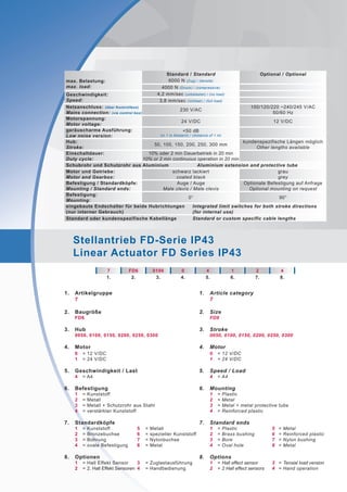
Hub
Stroke
50 100 150 200 250 300
A 228 278 338 388 448 498
B 278 378 488 588 698 798
Hubgeschwindigkeit[mm/s]
Speed[mm/s]
Hubkraft [N]
Lifting force [N]
Hubkraft [N]
Lifting force [N]
Strom[A]
Current[A]
Zug- / Druckbelastung
Tensile- / Compressive load
Zugbelastung
Push load
Hubgeschwindigkeit vs Hubkraft
Speed vs Load
Strom vs Hubkraft
Current vs Lifting Force](https://image.slidesharecdn.com/pproduktflyer-stellantriebe-seriefd1209deen280912-151118054048-lva1-app6891/85/Flyer-Stellantrieb-7-FD-de-en-3-320.jpg)


Das Dokument beschreibt die technischen Spezifikationen des Stellantriebs der FD-Serie, einschließlich maximaler Belastungen von 6000 N (Zug) und 4000 N (Druck), Geschwindigkeiten von bis zu 4,2 mm/sec und einer maximale Einschaltdauer von 10% oder 2 Minuten im Dauerbetrieb. Darüber hinaus sind verschiedene Hublängen, montierbare Optionen und zusätzliche Funktionen wie integrierte Hall-Effekt-Sensoren und Sicherheitsschalter aufgeführt. Die Informationen umfassen auch Details zur Motor-Spannung, Geräuschentwicklung und möglichen Montagearten.


