62-mal heruntergeladen

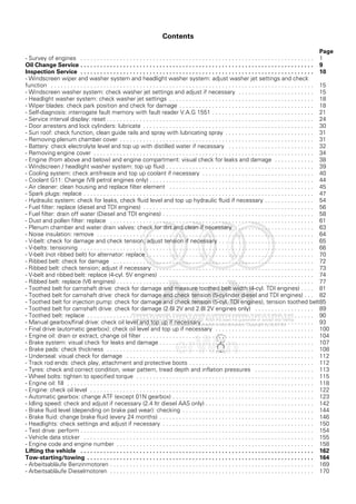
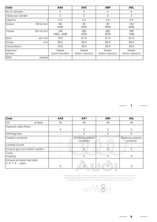
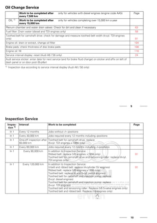
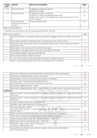
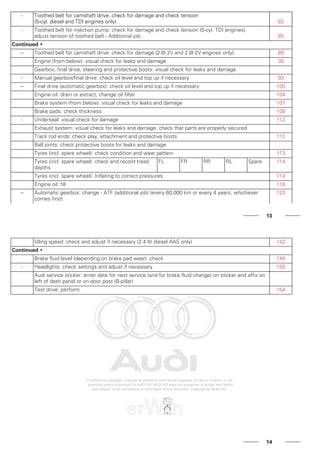
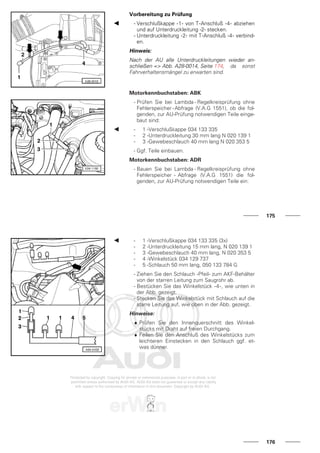

Das Dokument ist ein Wartungshandbuch für den Audi 100 von 1991 und bietet technische Informationen sowie Sicherheitsvorkehrungen, die von Mechanikern bei Wartungs- und Inspektionsarbeiten eingehalten werden müssen. Es enthält eine Übersicht über verschiedene Wartungsmaßnahmen, wie Ölwechsel, Inspektionen und die Überprüfung von Fahrzeugkomponenten, um die Verkehrssicherheit zu gewährleisten. Alle Anweisungen sind wichtig für die Gewährleistung der Straßenverkehrstauglichkeit des Fahrzeugs.