International Journal of Engineering Research and Development
•
1 gefällt mir•199 views

Electrical, Electronics and Computer Engineering, Information Engineering and Technology, Mechanical, Industrial and Manufacturing Engineering, Automation and Mechatronics Engineering, Material and Chemical Engineering, Civil and Architecture Engineering, Biotechnology and Bio Engineering, Environmental Engineering, Petroleum and Mining Engineering, Marine and Agriculture engineering, Aerospace Engineering.

Empfohlen
Empfohlen
Weitere ähnliche Inhalte
Was ist angesagt?
Was ist angesagt? (19)
Andere mochten auch
Andere mochten auch (20)
Ähnlich wie International Journal of Engineering Research and Development
Ähnlich wie International Journal of Engineering Research and Development (20)
Mehr von IJERD Editor
Mehr von IJERD Editor (20)
Kürzlich hochgeladen
Kürzlich hochgeladen (20)
International Journal of Engineering Research and Development
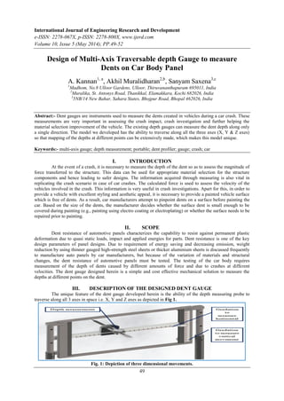
- 1. International Journal of Engineering Research and Development e-ISSN: 2278-067X, p-ISSN: 2278-800X, www.ijerd.com Volume 10, Issue 5 (May 2014), PP.49-52 49 Design of Multi-Axis Traversable depth Gauge to measure Dents on Car Body Panel A. Kannan1, a , Akhil Muralidharan2,b , Sanyam Saxena3,c 1 Madhom, No.8 Ulloor Gardens, Ulloor, Thiruvananthapuram 695011, India 2 Muralika, St. Antonys Road, Thanikkal, Elamakkara, Kochi 682026, India 3 5NB/14 New Bahar, Sahara States, Bhojpur Road, Bhopal 462026, India Abstract:- Dent gauges are instruments used to measure the dents created in vehicles during a car crash. These measurements are very important in assessing the crash impact, crash investigation and further helping the material selection improvement of the vehicle. The existing depth gauges can measure the dent depth along only a single direction. The model we developed has the ability to traverse along all the three axes (X, Y & Z axes) so that mapping of the depths at different points can be extensively made, which makes this model unique. Keywords:- multi-axis gauge; depth measurement; portable; dent profiler; gauge; crash; car I. INTRODUCTION At the event of a crash, it is necessary to measure the depth of the dent so as to assess the magnitude of force transferred to the structure. This data can be used for appropriate material selection for the structure components and hence leading to safer designs. The information acquired through measuring is also vital in replicating the crash scenario in case of car crashes. The calculated force is used to assess the velocity of the vehicles involved in the crash. This information is very useful in crash investigations. Apart for this, in order to provide a vehicle with excellent styling and aesthetic appeal, it is necessary to provide a painted vehicle surface which is free of dents. As a result, car manufacturers attempt to pinpoint dents on a surface before painting the car. Based on the size of the dents, the manufacturer decides whether the surface dent is small enough to be covered during painting (e.g., painting using electro coating or electroplating) or whether the surface needs to be repaired prior to painting. II. SCOPE Dent resistance of automotive panels characterizes the capability to resist against permanent plastic deformation due to quasi static loads, impact and applied energies for parts. Dent resistance is one of the key design parameters of panel designs. Due to requirement of energy saving and decreasing emission, weight reduction by using thinner gauged high-strength steel sheets or thicker aluminium sheets is discussed frequently to manufacture auto panels by car manufacturers, but because of the variation of materials and structural changes, the dent resistance of automotive panels must be tested. The testing of the car body requires measurement of the depth of dents caused by different amounts of force and due to crashes at different velocities. The dent gauge designed herein is a simple and cost effective mechanical solution to measure the depths at different points on the dent. III. DESCRIPTION OF THE DESIGNED DENT GAUGE The unique feature of the dent gauge developed herein is the ability of the depth measuring probe to traverse along all 3 axes in space i.e. X, Y and Z axes as depicted in Fig 1. Fig. 1: Depiction of three dimensional movements.
- 2. Design of Multi-Axis Traversable depth Gauge to measure Dents on Car Body Panel 50 The device can be extended using co-axial tubes which are locked by using pins. The maximum height attainable is 1.2 meters. Measurements can be made at any height between the minimum of 6.9 cm to 120 cm which is suitable for measuring practically most of the dents on cars. Upon folding the dimensions of the device reduces to 35 cm x 20 cm x 15 cm making it portable (Fig. 3). Fig. 2: Extensible support frame. Fig. 3: Folded state. The gauge may also be used by supporting itself on the body of the vehicle using vacuum suction cups as depicted in Fig 4. For this the support frame may be removed and also use of light weight material such as aluminium for the main frame helps facilitate this. Fig. 4: Use of vacuum suction cups (support frame removed) The primary components are: 1. Main frame: Made of aluminium to reduce weight so as to be fixed on to car body using vacuum suction cups if required and also to increase stability in fully extended state of the support frame. It supports the graduated bar used for vertical traverse. 2. Graduated bar for vertical traverse. Fig. 5: Graduated bar for vertical traverse. 3. Depth gauge holder which can move in horizontal direction by sliding on the graduated bar and marks the horizontally moved distance on the graduated bar. 4. Depth gauge which slides through the slot on the holder. The use of a dial gauge provides precise and easily readable depth measurements. A spherical ball which can rotate in along all axes is provided at the tip for easy movement along the surface of the car body. Fig. 6: Depth gauge with ball point.
- 3. Design of Multi-Axis Traversable depth Gauge to measure Dents on Car Body Panel 51 Specifications of designed model: Total height when in extended position = 120 cm Height when in folded position = 35 cm Height without support frame = 30 cm Mass (with support frame) = 5.5 Kg Mass (without support frame) = 700 g Length = 30 cm Total measurable height when placed on support frame = 6.9 cm to 120 cm Maximum measurable depth = 20 cm (can be increased using longer gauge) IV. ANALYSIS RESULTS STRUCTURAL ANALYSIS OF TELESCOPIC TUBE Fig. 7: Total deformation of tube due to buckling Fig. 8: Equivalent Elastic Strain of tube Fig. 9: Equivalent Stress induced in tube STRUCTURAL ANALYSIS OF BASE FRAME Fig. 10: Total deformation of base frame due to buckling Fig. 11: Equivalent Elastic Strain of base frame
- 4. Design of Multi-Axis Traversable depth Gauge to measure Dents on Car Body Panel 52 Fig.12: Equivalent Stress induced in base frame ANALYSIS RESULTS SUMMARY Model Max deformation due to buckling (mm) Max equivalent stress (MPa) Max equivalent strain Base frame 1.006 0.1586 1.078e-6 Telescopic pipe 1.004 0.2838 1.437e-6 V. PRESENT METHOD OF DENT EVALUATION In crash analysis, different software’s are used in calculating the velocities of the vehicles involved in an accident. This requires the profile of the dent caused due to the impact from which the force is calculated and thereby the velocities of cars. In order to create a digital version of the profile expensive high resolution cameras are used, even 3D cameras in some cases. VI. PROPOSED METHOD The proposed design of a dent gauge allows taking readings of depth at each point on the dent using the horizontal (X) and vertical (Y) coordinates obtained from the graduated scales present on the device. These servers as input to the software to create a digitized profile of the dent so as to do the necessary calculations to find the force, velocity and other parameters involved. VII. BENEFITS The main advantage here is the cost. Low-budget labs can make use of such a simple mechanical device in place of expensive cameras and highly complex algorithms used to create the profile from the captured images. This eliminates the investment on the cameras and skilled personnel required to operate it and also reduce the cost on computer equipment sincethe requirement for high computational power in processing the captured images are eliminated. REFERENCES [1] DhaferMarzougui, RandaRadwanSamaha, FadiTahan, Chongzhen Cui, Cing-Dao (Steve) Kan: “Extended Validation of the Finite Element Model for the 2002 Ford Explorer Sport Utility Vehicle”, NCAC 2012-W-002, July 2012. [2] Insurance Institute for Highway Safety, “Crash Test Report: 2002 Ford Explorer,” IIHS Test CEF0125, November 2001. [3] VV.AA. 2005. “Cost / benefit analyses of proposed systems [for Advanced vulnerable road user protection systems].” APROSYS report of WP2.1, Deliverable D2.1.2C. [4] Holmberg S, Nejabat B. Numerical assessment of stiffness and dent properties of automotive exterior panels[J]. Mater Des, 2004, 25: 361−368. [5] ASNAFI N. On strength, stiffness and dent resistance of car body panels[J]. J Mater ProcTechnol, 1995, 49: 13−31.