SlideShare ist ein Scribd-Unternehmen logo
1 von 6
International Journal of Engineering Inventions
e-ISSN: 2278-7461, p-ISSN: 2319-6491
Volume 2, Issue 6 (April 2013) PP: 38-43
www.ijeijournal.com Page | 38
Identification of changes in the microstructure of damaged
elements spherical joint
Mr. Sc. Mujanović Enes1
, Dr. Sc. Denijal Sprečić2
1,2
University of Tuzla, Faculty of Mechanical Engineering, Univerzitetska Str. 4, 75000 Tuzla,
Bosnia and Herzegovina
Abstract: Spherical joint are a special kind of mechanisms which serve to transmit the torque and the force
between the individual aggregates, respectively, in which case their shafts, connected with this gear, are under
certain constant angle or under a variable (changing) angle during the operation. These gear are widely used in
automobile industry. The main characteristic of these gears in that during the torque transmission relative
moving (displacing) in allowed, which can be under an angle or translatory and that, except for purely
mechanical losses, there are no other losses such as may be the torque inscrease or decrease. During the
operation damages occur on the parts (elements) of hinged gear. For this reason the analysis of the
microstructure is essntial to establish the causes and to decrease the damages on the observed parts.
Keywords: Mechanism, spherical joint, universal joint, microstructure, machine vision.
I. INTRODUCTION
The main parts of the universal joint are shaft and the hinged coupling. The Universal joints can have
one or more hinged couplings. The wide application and diversity of functional requirements conditioned the
creation of a high number of types of hinged couplings (spherical joints) of different constructions (designs), the
construction of a hinged coupling influencing the construction of universal joint. The hinged couplings are
basically divided into asynchronous and synchronous hinged couplings. The asynchronous hinged couplings
make possible the periodic variability of the angle velocity of the driven shaft, while the synchronous couplings
ensure a constant angle velocity of the outlet (driven) shaft, under the variable (changing) and relatively big
operating angles between the shafts.
II. THE ELEMENTS OF THE TRANSMISSION OF THE UNIVERSAL JOINT
The basic characteristic of the asynchronous gears is the periodic variability of the angle velocity of the
driven shaft, the variability being greater, the greater the angle between the intersecting shafts is.
7
6 5
4
3
2
1
Figure 1: Universal joint with constituent elements
From the group of asynchronous hinged couplings we performed laboratory analyses of the parts of the
universal joint. The universal joint is constructed in the form of two separate forks firmly connected to both
parts of the shaft. The legs of the forks are turned under the angle of 90o
one towards the other and they are
hinged interconnected by means of the cross. On the pins we set needle bearings which consist of a cover, safety
fuses, sleeve, needles and pickings which retain lubricant within the bearing. Those parts of the universal joints
which are subjected to the most intense strains are between the other cross axles and the sleeves of the needle
bearing. The asynchronous universal joint of the hinged type is illustrated in the Fig. 1, and consists of: 1-
bearing needle, 2-ring, 3-cross joint, 4-fork complete with a flange, 5,6-grease-gun and valve and 7-fork
complete with the shaft. Owing to unequal angle velocities of the driving and the driven shafts additional strains
of the above mentioned transmission parts (elements) occur, consequently, it is for this reason necessary to carry
out experimental laboratory analyses and to determine the deformations of the above mentioned parts of the
Identification of changes in the microstructure of damaged elements spherical joint
www.ijeijournal.com Page | 39
universal joint. Particularly interesting are the changes in the microstructure of the above mentioned parts which
occur during the testings of the above mentioned universal joints in operation.
III. LABORATORY ANALYSES OF THE MICROSTRUCTURE OF THE PARTS OF
UNIVERSAL JOINT
The analyses of the microstructure were carried out on the optical microscope. The microstructures
appeared after the corrosion of the sample in the reagent 1% HNO3 in ethyl alcohol, and the observation was
carried out at the magnification X 625. The analysis was carried out on the necks of the cross axle and on the
sleeves of the needle bearings. The picture of the microstructure of the cross-section of the neck is given in the
Fig. 2 and from the analysis of the photographic picture it is possible to see martensite + residual austenite
which is not desirable in the cemented layer because of its lower hardness. This indicates that the thermal
treatment was not performed well. Most probably the sample was heated to a higher temperature during its
tempering than it is allowable for this quality of treated steel which resulted in the increase of the austenite grain
so that a certain quantity of austenite was retained between the martensite needles during the cooling.
Figure 2: Neck sample; cross section; cemented layer,
martensite + residual austenite
Figure 3: Neck sample; longitudinal section;
cemented, layer; martensite + residual austenite
The picture of the microstructure of the longitudinal section of the sleeve is given in the Fig. 3, and
from the analysis of the photographic picture it can be seen that in the microstructure of the sleeve the cementite
is present on the grain border in the cemented layer in addition to martensite and the residual austenite. This
phenomenon in the structure occurs at higher temperatures of cementing by means of carbonizing. These
temperatures are not appropriate for the quality of the given steel in which case higher carbon content on the
surface is achieved. This results in the separation of cementite on the borders of grains. In parallel to the
appearance of cementite the grain increases too, which, in turn, increases the brittleness of the cemented layer.
Figure 4: Sleeve sample; cemented layer on the outer
edge; martensite + residual austenite + cementite
Figure 5: Sleeve sample; transit point between the
cemented layer and the core
IV. THE POSSIBLE APPLICATION OF THE MACHINE VISION TECHNIQUES
For more quality identification of microstructure changes on parts of spherical joints, with the clasical
laboratory test we proposed the possible application of the machine vision to the microstructure analysis parts of
the spherical joint. Improving basic inspection techniques may be accomplished by applying some new tools or
devices that make inspection points easier to see.
Identification of changes in the microstructure of damaged elements spherical joint
www.ijeijournal.com Page | 40
Part of the
spherical joint
CCD image
sensor
A/D
conversion
electronics
Embedded
processing
electronics
Interface Microprocessor
system
Database
Monitor Intelligent
system
SUBJECTIllumination
Decreasing/increasing the
illumination requirements
Analog
image data
Digital
image data
Compressed
image data
Software of MV for
microstructure
analysis
PC PLATFORM
Camera
control
Optic Lens
system
Figure 6: Generic schema of MVS for MA
Machine vision system will give us input information to intelligent system for microstructure
analysis.The structure of the proposed machine vision system for microstructure analysis (MVS for MA) is
shown in Fig. 6. In the cadre of the microstructure changes we marked the presence of: austenite, martensite,
benite, ferrite and etc. For that the size, shape and colour are key characteristics for visual monitoring change of
microstructure. It consists of next elements: microscope + CCD camera, PC platform – host processor system,
software for microstructure condition monitoring- application software for end-user (developed GUI which user
Neuro Inspector or IMAQ Vision functions as ActiveX control). Functional schema of proposed machine vision
system is shown on Fig. 7. It consists from three functions: image capturing,, image processing and features
extraction. Fig. 8 shows flowchart of MA (Microstructure Analysis) software development. The basic idea is to
develop a program which will be capable for automatic microstructure monitoring using image processing
techniques.
Image
capturing
AO
Image
processing
A1
Feature
extraction
A2
PC Platform
Microskope +
camera
Part of the
spherical joint
Set of rules for
image capturing
Image
processing
definition
Reference features
(features classes)
Captured image
Arithmetic operations
Thresholding
Color Pattern Matching
Blob Analysis and Morphology
Counting
IMAQ Vision Builder or Neuro
Inspector functions
Processed
image
Inputs in an
intelligent
system
Load
image(i)
START
Load
referent
masks
INPUT DATA
Referent image(s)
Directory of saved images (i)
IMAQ Vision
functions or
Neuro inspector
Pixel
value<Referent
value
i=i+1
i<Number of
images
END
Text
message
Text
message
Database
Figure 7: Functional schema of MV operations Figure 8: Flowchart of MA program
V. USING COMPUTER VISION TECHNIQUES TO THE ANALYSES OF THE
MICROSTRUCTURE
The analyses of the microstructure were carried out on the optical microscope. The microstructures
appeared after the corrosion of the sample in the reagent 1% HNO3 in ethyl alcohol, and the observation was
carried out at the magnification X 625. The analysis was carried out on the necks of the cross axle and on the
sleeves of the needle bearings. The picture of the microstructure of the cross-section of the neck is given in the
Fig. 9 and from the analysis of the photographic picture it is possible to see martensite + residual austenite
which is not desirable in the cemented layer because of its lower hardness. This indicates that the thermal
treatment was not performed well. Most probably the sample was heated to a higher temperature during its
tempering than it is allowable for this quality of treated steel which resulted in the increase of the austenite grain
so that a certain quantity of austenite was retained between the martensite needles during the cooling.
Identification of changes in the microstructure of damaged elements spherical joint
www.ijeijournal.com Page | 41
Figure 9: Image preparation
For example it’s shown of the microstructure of the cross-section of the neck, which was for easiest
analysis converted into JPEG format (8 bits grayscale) in IMAQ Vision Builder 6.1 software [6]. Other images,
which are interesting for analyze of universal joint elements, are prepared and converted in the same image
format Fig. 9. Image processing technique called BLOB (binary large objects) analysis is used for analyzing the
structure of joint elements.
Figure 10: Tresholding
Figure 11: Tresholding values
Next steps have been performed: filtering the image to sharpen edges, separating particles from the
background with tresholding Fig. 10, modifying blobs with morphological functions, analyzing the data.
Identification of changes in the microstructure of damaged elements spherical joint
www.ijeijournal.com Page | 42
Figure 12: Advanced Morphology
Figure 13: Remove small objects
Figure 14: Particle analysis
Figure 15: Measurement results
Morphological operations prepare blobs in the image for quantitative analysis such as finding the area,
perimeter, or orientation. Advanced Morphology technique is used for removing small objects that touch the
Identification of changes in the microstructure of damaged elements spherical joint
www.ijeijournal.com Page | 43
border of the image Fig. 12. The measurement results are exported to Microsoft Excel for further analysis Fig.
15.
VI. CONCLUSIONS
Base upon the performed laboratory analyses on the microstructure of the parts (elements) of the
universal joints all the samples of their damages can be classified into the damages resulting from poor
maintenance, wear during the operation and from poor construction and fabrication technology. Due to poorly
executed thermal - chemical treatments of the surfaces of the parts (elements) of the universal joints coarse-
grained structures of lower hardness occur. This is illustrated by the picture of the microstructure of the cross
section of the parts (elements) of the universal joints and measured hardness values on individual parts of these
sections. This phenomenon is more pronounced on the elements in operation on which a sudden temperature
increase occurs, and consequently, there are also the cases of noticeable plastic deformations in the form of
increased width of impressions. Better quality cementation and greater depth of the cemented layer, as well as a
better quality tempering and the yielding (releasing) period can influence the condition of the material on the
surface and on the layer below the surface. In this way it is possible to achieve during the operation decreased
damages on the parts (elements) of the universal joint as the integral part of the transmission mechanism. Beside
of classical laboratory approach, this paper presents using of the computer vision techniques for the analysis
microstructure of the parts of universal joint. Quality of information got it on this way gave sharpen picture
about microstructure changes of observed elements which are caused by action of complex loads.
REFERENCES
[1] Sprečić D.; Mujanović E.: Analysis of the Wear a Conical Gear Pairs, and the Possibility of Applying Machine Vision to Analyze
the Microstructure, Intelligent technologies in logistics and mechatronics systems Itelms', Panevėžys, Lithuania, May 03-04, 2012,
pp. 159-165.
[2] Williams J.A.: Engineering Tribology, Oxford University Press, 2005.
[3] Jain R.; Kasturi R.; Schunck G.B.: Machine Vision, McGraw-Hill, New York, 1995.
[4] Janičijević N.; Janković D.; Todorović I.: Konstrukcija motornih vozila, Beograd, Faculty of mechanical Engineering, 1998.
[5] Časnji F.; Klinar I.; Muzikravić V.: Savremene tendencije u automobilskoj tehnici – Mehaničke komponente i elektronski
sistemi,Novi Sad, 2001.
[6] Klinar I.: Oprema motora SUS, Novi Sad, Faculty of technical science, 1995.
[7] Holmberg K.; Matthews A.: Coatings Tribology, Properties, Techniques and Applications in Surface Engineering, Amsterdam,
1994.

Weitere ähnliche Inhalte

Was ist angesagt?

Improvement of tensile strength of butt welded joints prepared by vibratory w...
Improvement of tensile strength of butt welded joints prepared by vibratory w...Improvement of tensile strength of butt welded joints prepared by vibratory w...
Improvement of tensile strength of butt welded joints prepared by vibratory w...
IAEME Publication
 
Comparative study on different pin geometries of tool profile in friction sti...
Comparative study on different pin geometries of tool profile in friction sti...Comparative study on different pin geometries of tool profile in friction sti...
Comparative study on different pin geometries of tool profile in friction sti...
IAEME Publication
 

Was ist angesagt? (19)

Finite element analysis of aluminium alloys for their vibration characteristics
Finite element analysis of aluminium alloys for their vibration characteristicsFinite element analysis of aluminium alloys for their vibration characteristics
Finite element analysis of aluminium alloys for their vibration characteristics
 
Experimental And FE Analysis Of Eccentric Loaded Symmetrical And Unsymmetrica...
Experimental And FE Analysis Of Eccentric Loaded Symmetrical And Unsymmetrica...Experimental And FE Analysis Of Eccentric Loaded Symmetrical And Unsymmetrica...
Experimental And FE Analysis Of Eccentric Loaded Symmetrical And Unsymmetrica...
 
Embs project report
Embs project reportEmbs project report
Embs project report
 
Non Linear Finite Element Method of Analysis of Reinforced Concrete Deep Beam
Non Linear Finite Element Method of Analysis of Reinforced Concrete Deep BeamNon Linear Finite Element Method of Analysis of Reinforced Concrete Deep Beam
Non Linear Finite Element Method of Analysis of Reinforced Concrete Deep Beam
 
30720130101006
3072013010100630720130101006
30720130101006
 
Strength Analysis and Optimization Design about the key parts of the Robot
Strength Analysis and Optimization Design about the key parts of the RobotStrength Analysis and Optimization Design about the key parts of the Robot
Strength Analysis and Optimization Design about the key parts of the Robot
 
Medium Velocity Impact on Sandwich Beams
Medium Velocity Impact on Sandwich BeamsMedium Velocity Impact on Sandwich Beams
Medium Velocity Impact on Sandwich Beams
 
30120140501016
3012014050101630120140501016
30120140501016
 
International Journal of Engineering Research and Development (IJERD)
International Journal of Engineering Research and Development (IJERD)International Journal of Engineering Research and Development (IJERD)
International Journal of Engineering Research and Development (IJERD)
 
Behaviour Analysis of Corroded Wires Based on Statistical Models
Behaviour Analysis of Corroded Wires Based on Statistical ModelsBehaviour Analysis of Corroded Wires Based on Statistical Models
Behaviour Analysis of Corroded Wires Based on Statistical Models
 
Improvement of tensile strength of butt welded joints prepared by vibratory w...
Improvement of tensile strength of butt welded joints prepared by vibratory w...Improvement of tensile strength of butt welded joints prepared by vibratory w...
Improvement of tensile strength of butt welded joints prepared by vibratory w...
 
IRJET- Examination of Hardness Values for Ti-6Al-4V Welded Specimens and Micr...
IRJET- Examination of Hardness Values for Ti-6Al-4V Welded Specimens and Micr...IRJET- Examination of Hardness Values for Ti-6Al-4V Welded Specimens and Micr...
IRJET- Examination of Hardness Values for Ti-6Al-4V Welded Specimens and Micr...
 
Modal analysis of annular disc
Modal analysis of annular discModal analysis of annular disc
Modal analysis of annular disc
 
Finite element optimization of stator by casted and welded structures
Finite element optimization of stator by casted and welded structuresFinite element optimization of stator by casted and welded structures
Finite element optimization of stator by casted and welded structures
 
IRJET- A Study on the Behaviour of Double Layer Steel Braced Barrel Vaults
IRJET- A Study on the Behaviour of Double Layer Steel Braced Barrel VaultsIRJET- A Study on the Behaviour of Double Layer Steel Braced Barrel Vaults
IRJET- A Study on the Behaviour of Double Layer Steel Braced Barrel Vaults
 
Mechanical Engineering Technical Interview Q & A Metrology and precision inst...
Mechanical Engineering Technical Interview Q & A Metrology and precision inst...Mechanical Engineering Technical Interview Q & A Metrology and precision inst...
Mechanical Engineering Technical Interview Q & A Metrology and precision inst...
 
Comparative study on different pin geometries of tool profile in friction sti...
Comparative study on different pin geometries of tool profile in friction sti...Comparative study on different pin geometries of tool profile in friction sti...
Comparative study on different pin geometries of tool profile in friction sti...
 
Co25535539
Co25535539Co25535539
Co25535539
 
Experimental investigation of the effect of cold joint on strength and stiffn...
Experimental investigation of the effect of cold joint on strength and stiffn...Experimental investigation of the effect of cold joint on strength and stiffn...
Experimental investigation of the effect of cold joint on strength and stiffn...
 

Andere mochten auch (9)

Dudas y desafíos de las izquierdas latinoamericanas
Dudas y desafíos de las izquierdas latinoamericanasDudas y desafíos de las izquierdas latinoamericanas
Dudas y desafíos de las izquierdas latinoamericanas
 
Copia de profesora ana isabel de armelia
Copia de profesora ana isabel de armeliaCopia de profesora ana isabel de armelia
Copia de profesora ana isabel de armelia
 
K02067582
K02067582K02067582
K02067582
 
Untitled Presentation
Untitled PresentationUntitled Presentation
Untitled Presentation
 
Ucas day notes for pupils 2
Ucas day notes for pupils 2Ucas day notes for pupils 2
Ucas day notes for pupils 2
 
Soal olimpiade-matematika-tk-provinsi-2009
Soal olimpiade-matematika-tk-provinsi-2009Soal olimpiade-matematika-tk-provinsi-2009
Soal olimpiade-matematika-tk-provinsi-2009
 
O0206102106
O0206102106O0206102106
O0206102106
 
Τα φιλαράκια - Τεύχος Μαΐου 2013
Τα φιλαράκια - Τεύχος Μαΐου 2013Τα φιλαράκια - Τεύχος Μαΐου 2013
Τα φιλαράκια - Τεύχος Μαΐου 2013
 
3 n mito e logos
3 n mito e logos3 n mito e logos
3 n mito e logos
 

Ähnlich wie Identification of changes in the microstructure of damaged elements spherical joint

A study on plastic hinge formation in rc frame by nonlinear static analysis
A study on plastic hinge formation in rc frame by nonlinear static analysisA study on plastic hinge formation in rc frame by nonlinear static analysis
A study on plastic hinge formation in rc frame by nonlinear static analysis
eSAT Journals
 
Journal Published
Journal PublishedJournal Published
Journal Published
Rijo John
 

Ähnlich wie Identification of changes in the microstructure of damaged elements spherical joint (20)

Influence of Outrigger system in RC Structures for Different Seismic Zones
Influence of Outrigger system in RC Structures for Different Seismic ZonesInfluence of Outrigger system in RC Structures for Different Seismic Zones
Influence of Outrigger system in RC Structures for Different Seismic Zones
 
Review of shaft failure in Coil Car Assembly
Review of shaft failure in Coil Car AssemblyReview of shaft failure in Coil Car Assembly
Review of shaft failure in Coil Car Assembly
 
Pid
PidPid
Pid
 
D012431621
D012431621D012431621
D012431621
 
ANALYSIS OF CNC LATHE SPINDLE FOR MAXIMUM CUTTING FORCE CONDITION AND BEARING...
ANALYSIS OF CNC LATHE SPINDLE FOR MAXIMUM CUTTING FORCE CONDITION AND BEARING...ANALYSIS OF CNC LATHE SPINDLE FOR MAXIMUM CUTTING FORCE CONDITION AND BEARING...
ANALYSIS OF CNC LATHE SPINDLE FOR MAXIMUM CUTTING FORCE CONDITION AND BEARING...
 
A study on plastic hinge formation in rc frame by nonlinear static analysis
A study on plastic hinge formation in rc frame by nonlinear static analysisA study on plastic hinge formation in rc frame by nonlinear static analysis
A study on plastic hinge formation in rc frame by nonlinear static analysis
 
Analytical Study on Flexural Behaviour of RCC Slabs with Concealed Beams usin...
Analytical Study on Flexural Behaviour of RCC Slabs with Concealed Beams usin...Analytical Study on Flexural Behaviour of RCC Slabs with Concealed Beams usin...
Analytical Study on Flexural Behaviour of RCC Slabs with Concealed Beams usin...
 
IRJET- Design and Analysis of Chain Drive Power Transmission from Station...
IRJET-  	  Design and Analysis of Chain Drive Power Transmission from Station...IRJET-  	  Design and Analysis of Chain Drive Power Transmission from Station...
IRJET- Design and Analysis of Chain Drive Power Transmission from Station...
 
IRJET - Vibration Analysis Technique for the Diagnosis of Bearing Housing Vib...
IRJET - Vibration Analysis Technique for the Diagnosis of Bearing Housing Vib...IRJET - Vibration Analysis Technique for the Diagnosis of Bearing Housing Vib...
IRJET - Vibration Analysis Technique for the Diagnosis of Bearing Housing Vib...
 
CONTROL OF HYDRAULIC FORCES ON A SQUARE AND CIRCULAR CYLINDER USING MULTI-ELE...
CONTROL OF HYDRAULIC FORCES ON A SQUARE AND CIRCULAR CYLINDER USING MULTI-ELE...CONTROL OF HYDRAULIC FORCES ON A SQUARE AND CIRCULAR CYLINDER USING MULTI-ELE...
CONTROL OF HYDRAULIC FORCES ON A SQUARE AND CIRCULAR CYLINDER USING MULTI-ELE...
 
IRJET- Analysis of Stress and Bending Strength of Involutes Spur Gears with F...
IRJET- Analysis of Stress and Bending Strength of Involutes Spur Gears with F...IRJET- Analysis of Stress and Bending Strength of Involutes Spur Gears with F...
IRJET- Analysis of Stress and Bending Strength of Involutes Spur Gears with F...
 
IRJET- Dynamic Analysis on Vibration Grader
IRJET- Dynamic Analysis on Vibration GraderIRJET- Dynamic Analysis on Vibration Grader
IRJET- Dynamic Analysis on Vibration Grader
 
Journal Published
Journal PublishedJournal Published
Journal Published
 
COMPARATIVE STUDY OF DYNAMIC RESPONSE OF MONOLITHIC AND ROCKING COLUMNS UNDER...
COMPARATIVE STUDY OF DYNAMIC RESPONSE OF MONOLITHIC AND ROCKING COLUMNS UNDER...COMPARATIVE STUDY OF DYNAMIC RESPONSE OF MONOLITHIC AND ROCKING COLUMNS UNDER...
COMPARATIVE STUDY OF DYNAMIC RESPONSE OF MONOLITHIC AND ROCKING COLUMNS UNDER...
 
COMPARATIVE STUDY OF DYNAMIC RESPONSE OF MONOLITHIC AND ROCKING COLUMNS UNDER...
COMPARATIVE STUDY OF DYNAMIC RESPONSE OF MONOLITHIC AND ROCKING COLUMNS UNDER...COMPARATIVE STUDY OF DYNAMIC RESPONSE OF MONOLITHIC AND ROCKING COLUMNS UNDER...
COMPARATIVE STUDY OF DYNAMIC RESPONSE OF MONOLITHIC AND ROCKING COLUMNS UNDER...
 
STATIC AND DYNAMIC ANALYSIS OF HIGH SPEED MOTORIZED SPINDLE
STATIC AND DYNAMIC ANALYSIS OF HIGH SPEED MOTORIZED SPINDLESTATIC AND DYNAMIC ANALYSIS OF HIGH SPEED MOTORIZED SPINDLE
STATIC AND DYNAMIC ANALYSIS OF HIGH SPEED MOTORIZED SPINDLE
 
C010321630
C010321630C010321630
C010321630
 
Design and Analysis of A Partially Decoupled Minimally Invasive Surgical Robot
Design and Analysis of A Partially Decoupled Minimally Invasive Surgical RobotDesign and Analysis of A Partially Decoupled Minimally Invasive Surgical Robot
Design and Analysis of A Partially Decoupled Minimally Invasive Surgical Robot
 
Vibrational Analysis of Pinion Shaft for the Diagnose of Cracks in Heavy Load...
Vibrational Analysis of Pinion Shaft for the Diagnose of Cracks in Heavy Load...Vibrational Analysis of Pinion Shaft for the Diagnose of Cracks in Heavy Load...
Vibrational Analysis of Pinion Shaft for the Diagnose of Cracks in Heavy Load...
 
IRJET- Seismic Time History Performance of Conventional Multi-Outriggers with...
IRJET- Seismic Time History Performance of Conventional Multi-Outriggers with...IRJET- Seismic Time History Performance of Conventional Multi-Outriggers with...
IRJET- Seismic Time History Performance of Conventional Multi-Outriggers with...
 

Mehr von International Journal of Engineering Inventions www.ijeijournal.com

Mehr von International Journal of Engineering Inventions www.ijeijournal.com (20)

H04124548
H04124548H04124548
H04124548
 
G04123844
G04123844G04123844
G04123844
 
F04123137
F04123137F04123137
F04123137
 
E04122330
E04122330E04122330
E04122330
 
C04121115
C04121115C04121115
C04121115
 
B04120610
B04120610B04120610
B04120610
 
A04120105
A04120105A04120105
A04120105
 
F04113640
F04113640F04113640
F04113640
 
E04112135
E04112135E04112135
E04112135
 
D04111520
D04111520D04111520
D04111520
 
C04111114
C04111114C04111114
C04111114
 
B04110710
B04110710B04110710
B04110710
 
A04110106
A04110106A04110106
A04110106
 
I04105358
I04105358I04105358
I04105358
 
H04104952
H04104952H04104952
H04104952
 
G04103948
G04103948G04103948
G04103948
 
F04103138
F04103138F04103138
F04103138
 
E04102330
E04102330E04102330
E04102330
 
D04101822
D04101822D04101822
D04101822
 
C04101217
C04101217C04101217
C04101217
 

Kürzlich hochgeladen

Mckinsey foundation level Handbook for Viewing
Mckinsey foundation level Handbook for ViewingMckinsey foundation level Handbook for Viewing
Mckinsey foundation level Handbook for Viewing
Nauman Safdar
 
The Abortion pills for sale in Qatar@Doha [+27737758557] []Deira Dubai Kuwait
The Abortion pills for sale in Qatar@Doha [+27737758557] []Deira Dubai KuwaitThe Abortion pills for sale in Qatar@Doha [+27737758557] []Deira Dubai Kuwait
The Abortion pills for sale in Qatar@Doha [+27737758557] []Deira Dubai Kuwait
daisycvs
 

Kürzlich hochgeladen (20)

Famous Olympic Siblings from the 21st Century
Famous Olympic Siblings from the 21st CenturyFamous Olympic Siblings from the 21st Century
Famous Olympic Siblings from the 21st Century
 
Mckinsey foundation level Handbook for Viewing
Mckinsey foundation level Handbook for ViewingMckinsey foundation level Handbook for Viewing
Mckinsey foundation level Handbook for Viewing
 
Organizational Transformation Lead with Culture
Organizational Transformation Lead with CultureOrganizational Transformation Lead with Culture
Organizational Transformation Lead with Culture
 
Uneak White's Personal Brand Exploration Presentation
Uneak White's Personal Brand Exploration PresentationUneak White's Personal Brand Exploration Presentation
Uneak White's Personal Brand Exploration Presentation
 
joint cost.pptx COST ACCOUNTING Sixteenth Edition ...
joint cost.pptx  COST ACCOUNTING  Sixteenth Edition                          ...joint cost.pptx  COST ACCOUNTING  Sixteenth Edition                          ...
joint cost.pptx COST ACCOUNTING Sixteenth Edition ...
 
Marel Q1 2024 Investor Presentation from May 8, 2024
Marel Q1 2024 Investor Presentation from May 8, 2024Marel Q1 2024 Investor Presentation from May 8, 2024
Marel Q1 2024 Investor Presentation from May 8, 2024
 
Escorts in Nungambakkam Phone 8250092165 Enjoy 24/7 Escort Service Enjoy Your...
Escorts in Nungambakkam Phone 8250092165 Enjoy 24/7 Escort Service Enjoy Your...Escorts in Nungambakkam Phone 8250092165 Enjoy 24/7 Escort Service Enjoy Your...
Escorts in Nungambakkam Phone 8250092165 Enjoy 24/7 Escort Service Enjoy Your...
 
Paradip CALL GIRL❤7091819311❤CALL GIRLS IN ESCORT SERVICE WE ARE PROVIDING
Paradip CALL GIRL❤7091819311❤CALL GIRLS IN ESCORT SERVICE WE ARE PROVIDINGParadip CALL GIRL❤7091819311❤CALL GIRLS IN ESCORT SERVICE WE ARE PROVIDING
Paradip CALL GIRL❤7091819311❤CALL GIRLS IN ESCORT SERVICE WE ARE PROVIDING
 
TVB_The Vietnam Believer Newsletter_May 6th, 2024_ENVol. 006.pdf
TVB_The Vietnam Believer Newsletter_May 6th, 2024_ENVol. 006.pdfTVB_The Vietnam Believer Newsletter_May 6th, 2024_ENVol. 006.pdf
TVB_The Vietnam Believer Newsletter_May 6th, 2024_ENVol. 006.pdf
 
CROSS CULTURAL NEGOTIATION BY PANMISEM NS
CROSS CULTURAL NEGOTIATION BY PANMISEM NSCROSS CULTURAL NEGOTIATION BY PANMISEM NS
CROSS CULTURAL NEGOTIATION BY PANMISEM NS
 
Putting the SPARK into Virtual Training.pptx
Putting the SPARK into Virtual Training.pptxPutting the SPARK into Virtual Training.pptx
Putting the SPARK into Virtual Training.pptx
 
Lundin Gold - Q1 2024 Conference Call Presentation (Revised)
Lundin Gold - Q1 2024 Conference Call Presentation (Revised)Lundin Gold - Q1 2024 Conference Call Presentation (Revised)
Lundin Gold - Q1 2024 Conference Call Presentation (Revised)
 
Falcon Invoice Discounting: Empowering Your Business Growth
Falcon Invoice Discounting: Empowering Your Business GrowthFalcon Invoice Discounting: Empowering Your Business Growth
Falcon Invoice Discounting: Empowering Your Business Growth
 
Dr. Admir Softic_ presentation_Green Club_ENG.pdf
Dr. Admir Softic_ presentation_Green Club_ENG.pdfDr. Admir Softic_ presentation_Green Club_ENG.pdf
Dr. Admir Softic_ presentation_Green Club_ENG.pdf
 
Unveiling Falcon Invoice Discounting: Leading the Way as India's Premier Bill...
Unveiling Falcon Invoice Discounting: Leading the Way as India's Premier Bill...Unveiling Falcon Invoice Discounting: Leading the Way as India's Premier Bill...
Unveiling Falcon Invoice Discounting: Leading the Way as India's Premier Bill...
 
The Abortion pills for sale in Qatar@Doha [+27737758557] []Deira Dubai Kuwait
The Abortion pills for sale in Qatar@Doha [+27737758557] []Deira Dubai KuwaitThe Abortion pills for sale in Qatar@Doha [+27737758557] []Deira Dubai Kuwait
The Abortion pills for sale in Qatar@Doha [+27737758557] []Deira Dubai Kuwait
 
Horngren’s Cost Accounting A Managerial Emphasis, Canadian 9th edition soluti...
Horngren’s Cost Accounting A Managerial Emphasis, Canadian 9th edition soluti...Horngren’s Cost Accounting A Managerial Emphasis, Canadian 9th edition soluti...
Horngren’s Cost Accounting A Managerial Emphasis, Canadian 9th edition soluti...
 
Falcon's Invoice Discounting: Your Path to Prosperity
Falcon's Invoice Discounting: Your Path to ProsperityFalcon's Invoice Discounting: Your Path to Prosperity
Falcon's Invoice Discounting: Your Path to Prosperity
 
Cannabis Legalization World Map: 2024 Updated
Cannabis Legalization World Map: 2024 UpdatedCannabis Legalization World Map: 2024 Updated
Cannabis Legalization World Map: 2024 Updated
 
Arti Languages Pre Seed Teaser Deck 2024.pdf
Arti Languages Pre Seed Teaser Deck 2024.pdfArti Languages Pre Seed Teaser Deck 2024.pdf
Arti Languages Pre Seed Teaser Deck 2024.pdf
 

Identification of changes in the microstructure of damaged elements spherical joint

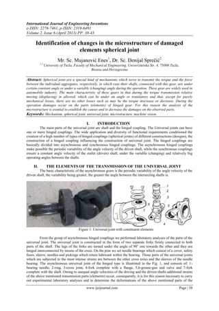
  • 1. International Journal of Engineering Inventions e-ISSN: 2278-7461, p-ISSN: 2319-6491 Volume 2, Issue 6 (April 2013) PP: 38-43 www.ijeijournal.com Page | 38 Identification of changes in the microstructure of damaged elements spherical joint Mr. Sc. Mujanović Enes1 , Dr. Sc. Denijal Sprečić2 1,2 University of Tuzla, Faculty of Mechanical Engineering, Univerzitetska Str. 4, 75000 Tuzla, Bosnia and Herzegovina Abstract: Spherical joint are a special kind of mechanisms which serve to transmit the torque and the force between the individual aggregates, respectively, in which case their shafts, connected with this gear, are under certain constant angle or under a variable (changing) angle during the operation. These gear are widely used in automobile industry. The main characteristic of these gears in that during the torque transmission relative moving (displacing) in allowed, which can be under an angle or translatory and that, except for purely mechanical losses, there are no other losses such as may be the torque inscrease or decrease. During the operation damages occur on the parts (elements) of hinged gear. For this reason the analysis of the microstructure is essntial to establish the causes and to decrease the damages on the observed parts. Keywords: Mechanism, spherical joint, universal joint, microstructure, machine vision. I. INTRODUCTION The main parts of the universal joint are shaft and the hinged coupling. The Universal joints can have one or more hinged couplings. The wide application and diversity of functional requirements conditioned the creation of a high number of types of hinged couplings (spherical joints) of different constructions (designs), the construction of a hinged coupling influencing the construction of universal joint. The hinged couplings are basically divided into asynchronous and synchronous hinged couplings. The asynchronous hinged couplings make possible the periodic variability of the angle velocity of the driven shaft, while the synchronous couplings ensure a constant angle velocity of the outlet (driven) shaft, under the variable (changing) and relatively big operating angles between the shafts. II. THE ELEMENTS OF THE TRANSMISSION OF THE UNIVERSAL JOINT The basic characteristic of the asynchronous gears is the periodic variability of the angle velocity of the driven shaft, the variability being greater, the greater the angle between the intersecting shafts is. 7 6 5 4 3 2 1 Figure 1: Universal joint with constituent elements From the group of asynchronous hinged couplings we performed laboratory analyses of the parts of the universal joint. The universal joint is constructed in the form of two separate forks firmly connected to both parts of the shaft. The legs of the forks are turned under the angle of 90o one towards the other and they are hinged interconnected by means of the cross. On the pins we set needle bearings which consist of a cover, safety fuses, sleeve, needles and pickings which retain lubricant within the bearing. Those parts of the universal joints which are subjected to the most intense strains are between the other cross axles and the sleeves of the needle bearing. The asynchronous universal joint of the hinged type is illustrated in the Fig. 1, and consists of: 1- bearing needle, 2-ring, 3-cross joint, 4-fork complete with a flange, 5,6-grease-gun and valve and 7-fork complete with the shaft. Owing to unequal angle velocities of the driving and the driven shafts additional strains of the above mentioned transmission parts (elements) occur, consequently, it is for this reason necessary to carry out experimental laboratory analyses and to determine the deformations of the above mentioned parts of the
  • 2. Identification of changes in the microstructure of damaged elements spherical joint www.ijeijournal.com Page | 39 universal joint. Particularly interesting are the changes in the microstructure of the above mentioned parts which occur during the testings of the above mentioned universal joints in operation. III. LABORATORY ANALYSES OF THE MICROSTRUCTURE OF THE PARTS OF UNIVERSAL JOINT The analyses of the microstructure were carried out on the optical microscope. The microstructures appeared after the corrosion of the sample in the reagent 1% HNO3 in ethyl alcohol, and the observation was carried out at the magnification X 625. The analysis was carried out on the necks of the cross axle and on the sleeves of the needle bearings. The picture of the microstructure of the cross-section of the neck is given in the Fig. 2 and from the analysis of the photographic picture it is possible to see martensite + residual austenite which is not desirable in the cemented layer because of its lower hardness. This indicates that the thermal treatment was not performed well. Most probably the sample was heated to a higher temperature during its tempering than it is allowable for this quality of treated steel which resulted in the increase of the austenite grain so that a certain quantity of austenite was retained between the martensite needles during the cooling. Figure 2: Neck sample; cross section; cemented layer, martensite + residual austenite Figure 3: Neck sample; longitudinal section; cemented, layer; martensite + residual austenite The picture of the microstructure of the longitudinal section of the sleeve is given in the Fig. 3, and from the analysis of the photographic picture it can be seen that in the microstructure of the sleeve the cementite is present on the grain border in the cemented layer in addition to martensite and the residual austenite. This phenomenon in the structure occurs at higher temperatures of cementing by means of carbonizing. These temperatures are not appropriate for the quality of the given steel in which case higher carbon content on the surface is achieved. This results in the separation of cementite on the borders of grains. In parallel to the appearance of cementite the grain increases too, which, in turn, increases the brittleness of the cemented layer. Figure 4: Sleeve sample; cemented layer on the outer edge; martensite + residual austenite + cementite Figure 5: Sleeve sample; transit point between the cemented layer and the core IV. THE POSSIBLE APPLICATION OF THE MACHINE VISION TECHNIQUES For more quality identification of microstructure changes on parts of spherical joints, with the clasical laboratory test we proposed the possible application of the machine vision to the microstructure analysis parts of the spherical joint. Improving basic inspection techniques may be accomplished by applying some new tools or devices that make inspection points easier to see.
  • 3. Identification of changes in the microstructure of damaged elements spherical joint www.ijeijournal.com Page | 40 Part of the spherical joint CCD image sensor A/D conversion electronics Embedded processing electronics Interface Microprocessor system Database Monitor Intelligent system SUBJECTIllumination Decreasing/increasing the illumination requirements Analog image data Digital image data Compressed image data Software of MV for microstructure analysis PC PLATFORM Camera control Optic Lens system Figure 6: Generic schema of MVS for MA Machine vision system will give us input information to intelligent system for microstructure analysis.The structure of the proposed machine vision system for microstructure analysis (MVS for MA) is shown in Fig. 6. In the cadre of the microstructure changes we marked the presence of: austenite, martensite, benite, ferrite and etc. For that the size, shape and colour are key characteristics for visual monitoring change of microstructure. It consists of next elements: microscope + CCD camera, PC platform – host processor system, software for microstructure condition monitoring- application software for end-user (developed GUI which user Neuro Inspector or IMAQ Vision functions as ActiveX control). Functional schema of proposed machine vision system is shown on Fig. 7. It consists from three functions: image capturing,, image processing and features extraction. Fig. 8 shows flowchart of MA (Microstructure Analysis) software development. The basic idea is to develop a program which will be capable for automatic microstructure monitoring using image processing techniques. Image capturing AO Image processing A1 Feature extraction A2 PC Platform Microskope + camera Part of the spherical joint Set of rules for image capturing Image processing definition Reference features (features classes) Captured image Arithmetic operations Thresholding Color Pattern Matching Blob Analysis and Morphology Counting IMAQ Vision Builder or Neuro Inspector functions Processed image Inputs in an intelligent system Load image(i) START Load referent masks INPUT DATA Referent image(s) Directory of saved images (i) IMAQ Vision functions or Neuro inspector Pixel value<Referent value i=i+1 i<Number of images END Text message Text message Database Figure 7: Functional schema of MV operations Figure 8: Flowchart of MA program V. USING COMPUTER VISION TECHNIQUES TO THE ANALYSES OF THE MICROSTRUCTURE The analyses of the microstructure were carried out on the optical microscope. The microstructures appeared after the corrosion of the sample in the reagent 1% HNO3 in ethyl alcohol, and the observation was carried out at the magnification X 625. The analysis was carried out on the necks of the cross axle and on the sleeves of the needle bearings. The picture of the microstructure of the cross-section of the neck is given in the Fig. 9 and from the analysis of the photographic picture it is possible to see martensite + residual austenite which is not desirable in the cemented layer because of its lower hardness. This indicates that the thermal treatment was not performed well. Most probably the sample was heated to a higher temperature during its tempering than it is allowable for this quality of treated steel which resulted in the increase of the austenite grain so that a certain quantity of austenite was retained between the martensite needles during the cooling.
  • 4. Identification of changes in the microstructure of damaged elements spherical joint www.ijeijournal.com Page | 41 Figure 9: Image preparation For example it’s shown of the microstructure of the cross-section of the neck, which was for easiest analysis converted into JPEG format (8 bits grayscale) in IMAQ Vision Builder 6.1 software [6]. Other images, which are interesting for analyze of universal joint elements, are prepared and converted in the same image format Fig. 9. Image processing technique called BLOB (binary large objects) analysis is used for analyzing the structure of joint elements. Figure 10: Tresholding Figure 11: Tresholding values Next steps have been performed: filtering the image to sharpen edges, separating particles from the background with tresholding Fig. 10, modifying blobs with morphological functions, analyzing the data.
  • 5. Identification of changes in the microstructure of damaged elements spherical joint www.ijeijournal.com Page | 42 Figure 12: Advanced Morphology Figure 13: Remove small objects Figure 14: Particle analysis Figure 15: Measurement results Morphological operations prepare blobs in the image for quantitative analysis such as finding the area, perimeter, or orientation. Advanced Morphology technique is used for removing small objects that touch the
  • 6. Identification of changes in the microstructure of damaged elements spherical joint www.ijeijournal.com Page | 43 border of the image Fig. 12. The measurement results are exported to Microsoft Excel for further analysis Fig. 15. VI. CONCLUSIONS Base upon the performed laboratory analyses on the microstructure of the parts (elements) of the universal joints all the samples of their damages can be classified into the damages resulting from poor maintenance, wear during the operation and from poor construction and fabrication technology. Due to poorly executed thermal - chemical treatments of the surfaces of the parts (elements) of the universal joints coarse- grained structures of lower hardness occur. This is illustrated by the picture of the microstructure of the cross section of the parts (elements) of the universal joints and measured hardness values on individual parts of these sections. This phenomenon is more pronounced on the elements in operation on which a sudden temperature increase occurs, and consequently, there are also the cases of noticeable plastic deformations in the form of increased width of impressions. Better quality cementation and greater depth of the cemented layer, as well as a better quality tempering and the yielding (releasing) period can influence the condition of the material on the surface and on the layer below the surface. In this way it is possible to achieve during the operation decreased damages on the parts (elements) of the universal joint as the integral part of the transmission mechanism. Beside of classical laboratory approach, this paper presents using of the computer vision techniques for the analysis microstructure of the parts of universal joint. Quality of information got it on this way gave sharpen picture about microstructure changes of observed elements which are caused by action of complex loads. REFERENCES [1] Sprečić D.; Mujanović E.: Analysis of the Wear a Conical Gear Pairs, and the Possibility of Applying Machine Vision to Analyze the Microstructure, Intelligent technologies in logistics and mechatronics systems Itelms', Panevėžys, Lithuania, May 03-04, 2012, pp. 159-165. [2] Williams J.A.: Engineering Tribology, Oxford University Press, 2005. [3] Jain R.; Kasturi R.; Schunck G.B.: Machine Vision, McGraw-Hill, New York, 1995. [4] Janičijević N.; Janković D.; Todorović I.: Konstrukcija motornih vozila, Beograd, Faculty of mechanical Engineering, 1998. [5] Časnji F.; Klinar I.; Muzikravić V.: Savremene tendencije u automobilskoj tehnici – Mehaničke komponente i elektronski sistemi,Novi Sad, 2001. [6] Klinar I.: Oprema motora SUS, Novi Sad, Faculty of technical science, 1995. [7] Holmberg K.; Matthews A.: Coatings Tribology, Properties, Techniques and Applications in Surface Engineering, Amsterdam, 1994.