Schweissnahtsymbole kompakt BS499 / ISO 2553 vectorized
•
2 gefällt mir•8,721 views

German / Deutsche Bezeichnung
Melden
Teilen
Melden
Teilen
Downloaden Sie, um offline zu lesen
Empfohlen
Welding symbol
The document discusses welding symbols according to BS 499 part 2. It provides examples of common welding symbols including types of butt welds like single-V and single-U, supplementary symbols like those indicating non-destructive testing and peripheral welds, dimension symbols showing throat thickness and leg length, multiple staggered weld elements, and other symbols like plug welds and seam welds. The document serves as a reference for interpreting welding symbols specified in BS 499 part 2.
Wis5 welding symbols 05
This document provides information on welding symbols according to BS 499 part 2 and BS EN 22553 (ISO 2553) standards. It explains the components and rules for welding symbols, including the arrow line, reference line, symbol, dimensions and supplementary information. Various weld types and processes are defined through symbols, such as fillet welds, butt welds, plug welds and numerical codes for welding processes. Dimensioning rules, representations of weld profiles, and examples of interpreting welding symbols from drawings are also covered.
04 wis5 symbol
The document discusses welding symbols according to BS 499 part 2 and BS EN 22553 (ISO 2553) standards. It provides information on the components and rules for welding symbols, including arrow lines, reference lines, dimensions, and supplementary information. Examples of various weld types and symbols like fillet welds, butt welds, and flared flange welds are presented. Numerical codes for different welding processes are also listed. The document aims to explain the standards for welding symbols used on engineering drawings.
Weld design symbols
The document discusses welding symbols and weld joint design according to ISO standards. It covers elementary weld symbols, supplementary symbols, dimensioning of welds, examples of weld joint applications, edge preparation, basic joint types including butt, tee, lap and corner joints, applicable welds for each joint type, and welding positions.
Welding Symbol.ppt
Welding symbols were developed to provide more information than simply indicating "weld here" on engineering drawings. There are various international standards for welding symbols, including AWS A2.4 in the US and ISO 2553 internationally. While similar, there are differences between standards that can cause confusion. It is important to understand which standard is being referenced when interpreting welding symbols.
Cswip welding-inspection-notes-and-questions-1
This document provides an overview of welding inspection for steels. It defines key terminology related to welding and discusses the duties of a welding inspector, including visual inspection, use of aids, and following inspection codes and standards. It also covers welding procedures, essential variables, joint preparation, weld sizes, defects, testing methods, and more. The goal is to provide comprehensive guidance on properly inspecting welded steel structures.
pipe welding
Pipe welding involves joining pipes together without fittings through various welding positions and techniques. It is more complicated than structural welding due to the cylindrical shape of pipes. There are four principal pipe welding positions defined by the orientation of the pipe: horizontal rolled (1G), vertical (2G), horizontal fixed (5G), and 45-degree inclined (6G). Additionally, there are restricted positions (R), fillet welds (F), and groove welds (G) used in pipe welding. Improperly executed pipe welds can lead to ultimate failure of the pipe at the welding point.
How to produce PQR
This document outlines the 8 steps to produce a Procedure Qualification Record (PQR) according to the ASME Section IX code. The steps are: 1) identify essential variables for the welding process, 2) add remaining essential variables from construction codes, 3) fill out the PQR format, 4) choose a qualified welder, 5) record welding parameters, 6) perform visual and mechanical tests, 7) record test results on the PQR, and 8) sign and date the completed PQR.
Welding Symbols
Welding is a method of permanently joining metal parts. There are different types of welded joints and standardized welding symbols are used on drawings to indicate how parts should be welded together. The symbols provide information on the type of weld, location of the weld, size of the weld, whether welding is required on one or both sides of the joint, and other details. Proper interpretation and application of welding symbols is important for ensuring parts are welded correctly.
Welding Inspection Cswip
The document discusses key terminology and concepts related to welding inspection. Some key points:
- It defines different types of welds (e.g. butt weld, fillet weld), joints (e.g. butt, tee, lap), and weld zones (e.g. weld metal, heat affected zone).
- It discusses joint preparation details like bevel angles, root faces, gaps for different joint types (e.g. single V, single J).
- It covers features of fillet welds like leg length, throat thickness, and how they relate. Leg length and throat thickness determine weld strength.
- It also discusses duties of a welding inspector like observing welding, recording
criteria of weld defects
The document discusses weld defect acceptance criteria according to different codes such as ASTM B31.1, ASME VIII, ASME B31.3, and AWS D1.1. It provides details on acceptance limits for various weld defects depending on the examination method, material thickness, loading conditions, and material application. Defects discussed include cracks, lack of fusion, incomplete penetration, undercuts, porosity, and reinforcement. Acceptance criteria include maximum defect sizes, numbers of defects allowed, cumulative lengths of defects, and distances between defects.
Welding Presentation
1. Welding is a metal joining process that involves applying heat, pressure, or both to joining materials. There are several types of welding processes including solid state welding, fusion welding, and pressure welding.
2. Solid state welding joins metals below their melting point using mechanical pressure and heat. Examples are cold welding, ultrasonic welding, friction welding, and friction stir welding.
3. Resistance welding generates heat for welding through electrical resistance across components. Common resistance welding methods are spot welding, seam welding, and projection welding.
Wis5 stress and distortion 15
The document discusses residual stresses and distortion that occur during welding. It explains that residual stresses develop due to local expansion and contraction during welding, and are locked in as elastic strain. Distortion results from the movement caused by these welding stresses. The document outlines various factors that influence residual stress and distortion, such as heat input, restraint, and weld metal volume. It also discusses different types of distortion and several techniques for controlling distortion, such as joint design, offsetting, balanced welding, and clamping.
Welding electrode
This document discusses welding electrodes and welding processes. It provides specifications for AC transformers and DC generators used in welding. It compares AC and DC arc welding, highlighting differences in power consumption, arc stability, electrode types, polarity, suitability for materials, and efficiency. It also compares MIG and TIG welding processes based on electrode type, feed method, current type, feed material, base metal thickness, and welding speed. The document outlines flux coatings used in electrodes and their ingredients for slag formation, arc stabilization, deoxidization, alloying, and binding. It describes coding systems for electrodes and factors to consider when selecting electrodes, such as the power source, base metal composition, thickness, position, current, and desired mechanical
How to Qualify a Welding Procedure
The document outlines the five step process to qualify a welding procedure according to ASME Section IX. It provides details on developing a draft procedure using 0.75" A36 steel plate welded in the flat position using GTAW and GMAW. Variables such as joint design, base metal and thickness, filler metal type and size, welding position, and electrical parameters are documented. The qualification weld was tested to verify it results in an acceptable weld with proper mechanical properties before the welding procedure specification can be used in construction.
Welding symbols
This document defines and explains common welding symbols used in technical drawings. It begins by identifying the required elements of a basic welding symbol: the reference line, arrow, and tail. The tail indicates welding processes and specifications. Additional symbols convey information like weld size, location, type (e.g. fillet, groove), and intermittent patterns. Terminology for different sides of the joint is also defined. In summary, the document provides an overview of standard welding symbols and their components used to communicate welding requirements in technical drawings and specifications.
Welding defects
This document provides a classification and overview of common welding defects. It divides defects into three main categories: planar defects, linear volumetric defects, and non-planar defects. Examples of each type of defect are given. The document also describes specific defect types such as cracks, inclusions, lack of fusion, porosity, overlap, undercut and provides potential causes of each.
3 weld symbols
This document defines common welding terms and symbols used in fabrication and engineering industries. It discusses different types of welds like butt welds and fillet welds. It describes parts of welds like the weld face, root, and heat affected zone. It also covers weld sizes, positions indicated by numerical codes, and the use of welding symbols on drawings to convey essential joint information in a standardized way.
Slip on flange welding according TO asme b31.3
This document discusses slip-on flange welding according to ASME B31.3-2016 standards. It explains that slip-on flange welding uses an equal fillet weld and the weld size is measured by the leg length using a welding gauge. It provides equations for calculating the fillet weld size on both the flange face side and hub end side based on the pipe wall thickness and hub thickness. A practical example is given to demonstrate calculating the weld sizes for a sample stainless steel flange.
cswip-3-1-new-book
This document provides an overview of welding inspection including:
- Typical duties of welding inspectors such as visual inspection, reviewing documentation, and checking welding processes
- Terms and definitions used in welding inspection
- Features that inspectors examine on completed welds such as penetration and types of joints
- Conditions required for visual inspection including lighting and access
- Stages when inspection is typically required including before, during, and after welding
- Records and documentation that inspectors are responsible for collecting and maintaining
The document serves as a reference for welding inspectors, outlining their key responsibilities and areas of focus.
Welding electrodes Classification & baking
An electrode is a coated metal wire used in welding. There are consumable electrodes that are consumed during welding like in stick welding, and non-consumable electrodes like in TIG welding. The numbers and letters on electrodes indicate properties like tensile strength and position used. Electrodes are classified as basic, cellulosic, rutile, or high iron powder based on coating composition and intended use. Basic electrodes require baking and provide high strength welds. Cellulosic electrodes do not require baking but produce higher hydrogen welds. Rutile electrodes are for general fabrication and baking is optional. Electrodes must be baked if exposed to air beyond specifications to remove moisture.
16 wis5 consumable
This document discusses welding consumables used in various welding processes. It describes the types of consumables which may include filler wires, covered electrodes, shielding gases, and fluxes. For each consumable type, details are provided on their composition, characteristics, and functions. Standards for different consumables are also outlined. The key information covered includes the critical role of consumables in welding, their composition and how they influence the weld quality and properties.
Welding design
The document discusses various welded joint geometries including butt, corner, T, lap, and edge joints as well as their advantages and disadvantages. It provides examples of different edge shapes and symbols used for each type of joint. Key terms are defined, such as butting member, nonbutting member, and splice member, and load reactions in welded joints are illustrated.
Cswip welding inspection notes and questions
The document discusses the duties of a welding inspector, including visual inspection of welds to identify defects and ensure they meet acceptance criteria. It describes tools that can aid inspection like magnification lenses. It outlines a code of practice for an inspection department, including checking documents, materials, equipment and welder qualifications before welding, monitoring the welding process and variables during welding, and inspecting the final weld for defects, dimensions and heat treatment after welding. Repairs should follow an authorized procedure and be re-inspected upon completion.
Fasteners
The document discusses various types of fasteners used to join parts in automobiles. It describes different threaded fasteners like bolts, nuts, and screws with imperial and metric sizing. Other fasteners mentioned include washers, rivets, clips, studs, and adhesives. Guidelines are provided on properly installing and tightening different fasteners.
Piping welding notes for beginners
Here are the major responsibilities of a project engineer summarized:
- Oversee all construction activities to ensure they are completed as per approved plans, schedule and budget.
- Coordinate with different project departments like safety, procurement, contracts and quality.
- Ensure materials are available on time and resolve any technical or design issues that arise.
- Lead meetings and ensure contractor action plans and schedules are understood.
- Review invoices, punch lists and change orders for approval.
- Oversee commissioning, documentation handover and project closeout.
- Monitor project progress and address any delays by expediting work or investigating causes.
WELDING JOINT DESING AND WELDINGSYMBOLS
This document discusses welding joint design and welding symbols. It begins by defining the five basic weld joint designs: butt, lap, corner, tee, and edge joints. It then covers factors to consider when selecting a joint type and reviewing weld symbol components. The document provides examples of welding symbols and explains how to interpret them to determine the required weld, including dimensions. It concludes by giving examples of interpreting and completing welding symbols.
Welding
This document defines welding codes, standards, and welding procedures. It discusses that a standard is a collection of documents containing codes, specifications, recommended practices, classifications, and guidelines that have been prepared by an institution or organization and approved according to existing procedures. A code is a standard that contains conditions and requirements related to a particular subject and indicates that the procedures used comply with the requirements. A specification is a standard that contains detailed and accurate technical requirements for materials, products, systems or services. It provides examples of welding codes from various organizations and discusses the essential variables and requirements for qualifying welding procedures according to ASME and EN standards.
Weld joint geometry and welding symbols
This document discusses types of welds including groove welds. There are nine categories of welds associated with welding symbols including groove, fillet, plug, stud, spot, seam, backing, surfacing, and flange welds. Groove welds are made in a groove between work pieces and there are eight types: square, scarf, V, bevel, U, J, flare-V, and flare-bevel grooves. The type of groove weld used depends on considerations like joint accessibility, welding process, structural design suitability, and cost.
Srep31295
1. The document describes peptides designed to mimic the discontinuous VEGF receptor-binding site on VEGF, which is important for VEGF's angiogenic properties.
2. Two peptide fragments from different regions of VEGF that interact with the receptor were synthesized and joined together with amino acid linkers of varying lengths.
3. Testing showed the joined peptides promoted VEGF receptor phosphorylation in cells and stimulated angiogenesis signaling pathways, similarly to native VEGF, with the longest linker peptide being most potent. This suggests the peptides can modulate the angiogenic response by mimicking VEGF's receptor interaction.
Weitere ähnliche Inhalte
Was ist angesagt?
Welding Symbols
Welding is a method of permanently joining metal parts. There are different types of welded joints and standardized welding symbols are used on drawings to indicate how parts should be welded together. The symbols provide information on the type of weld, location of the weld, size of the weld, whether welding is required on one or both sides of the joint, and other details. Proper interpretation and application of welding symbols is important for ensuring parts are welded correctly.
Welding Inspection Cswip
The document discusses key terminology and concepts related to welding inspection. Some key points:
- It defines different types of welds (e.g. butt weld, fillet weld), joints (e.g. butt, tee, lap), and weld zones (e.g. weld metal, heat affected zone).
- It discusses joint preparation details like bevel angles, root faces, gaps for different joint types (e.g. single V, single J).
- It covers features of fillet welds like leg length, throat thickness, and how they relate. Leg length and throat thickness determine weld strength.
- It also discusses duties of a welding inspector like observing welding, recording
criteria of weld defects
The document discusses weld defect acceptance criteria according to different codes such as ASTM B31.1, ASME VIII, ASME B31.3, and AWS D1.1. It provides details on acceptance limits for various weld defects depending on the examination method, material thickness, loading conditions, and material application. Defects discussed include cracks, lack of fusion, incomplete penetration, undercuts, porosity, and reinforcement. Acceptance criteria include maximum defect sizes, numbers of defects allowed, cumulative lengths of defects, and distances between defects.
Welding Presentation
1. Welding is a metal joining process that involves applying heat, pressure, or both to joining materials. There are several types of welding processes including solid state welding, fusion welding, and pressure welding.
2. Solid state welding joins metals below their melting point using mechanical pressure and heat. Examples are cold welding, ultrasonic welding, friction welding, and friction stir welding.
3. Resistance welding generates heat for welding through electrical resistance across components. Common resistance welding methods are spot welding, seam welding, and projection welding.
Wis5 stress and distortion 15
The document discusses residual stresses and distortion that occur during welding. It explains that residual stresses develop due to local expansion and contraction during welding, and are locked in as elastic strain. Distortion results from the movement caused by these welding stresses. The document outlines various factors that influence residual stress and distortion, such as heat input, restraint, and weld metal volume. It also discusses different types of distortion and several techniques for controlling distortion, such as joint design, offsetting, balanced welding, and clamping.
Welding electrode
This document discusses welding electrodes and welding processes. It provides specifications for AC transformers and DC generators used in welding. It compares AC and DC arc welding, highlighting differences in power consumption, arc stability, electrode types, polarity, suitability for materials, and efficiency. It also compares MIG and TIG welding processes based on electrode type, feed method, current type, feed material, base metal thickness, and welding speed. The document outlines flux coatings used in electrodes and their ingredients for slag formation, arc stabilization, deoxidization, alloying, and binding. It describes coding systems for electrodes and factors to consider when selecting electrodes, such as the power source, base metal composition, thickness, position, current, and desired mechanical
How to Qualify a Welding Procedure
The document outlines the five step process to qualify a welding procedure according to ASME Section IX. It provides details on developing a draft procedure using 0.75" A36 steel plate welded in the flat position using GTAW and GMAW. Variables such as joint design, base metal and thickness, filler metal type and size, welding position, and electrical parameters are documented. The qualification weld was tested to verify it results in an acceptable weld with proper mechanical properties before the welding procedure specification can be used in construction.
Welding symbols
This document defines and explains common welding symbols used in technical drawings. It begins by identifying the required elements of a basic welding symbol: the reference line, arrow, and tail. The tail indicates welding processes and specifications. Additional symbols convey information like weld size, location, type (e.g. fillet, groove), and intermittent patterns. Terminology for different sides of the joint is also defined. In summary, the document provides an overview of standard welding symbols and their components used to communicate welding requirements in technical drawings and specifications.
Welding defects
This document provides a classification and overview of common welding defects. It divides defects into three main categories: planar defects, linear volumetric defects, and non-planar defects. Examples of each type of defect are given. The document also describes specific defect types such as cracks, inclusions, lack of fusion, porosity, overlap, undercut and provides potential causes of each.
3 weld symbols
This document defines common welding terms and symbols used in fabrication and engineering industries. It discusses different types of welds like butt welds and fillet welds. It describes parts of welds like the weld face, root, and heat affected zone. It also covers weld sizes, positions indicated by numerical codes, and the use of welding symbols on drawings to convey essential joint information in a standardized way.
Slip on flange welding according TO asme b31.3
This document discusses slip-on flange welding according to ASME B31.3-2016 standards. It explains that slip-on flange welding uses an equal fillet weld and the weld size is measured by the leg length using a welding gauge. It provides equations for calculating the fillet weld size on both the flange face side and hub end side based on the pipe wall thickness and hub thickness. A practical example is given to demonstrate calculating the weld sizes for a sample stainless steel flange.
cswip-3-1-new-book
This document provides an overview of welding inspection including:
- Typical duties of welding inspectors such as visual inspection, reviewing documentation, and checking welding processes
- Terms and definitions used in welding inspection
- Features that inspectors examine on completed welds such as penetration and types of joints
- Conditions required for visual inspection including lighting and access
- Stages when inspection is typically required including before, during, and after welding
- Records and documentation that inspectors are responsible for collecting and maintaining
The document serves as a reference for welding inspectors, outlining their key responsibilities and areas of focus.
Welding electrodes Classification & baking
An electrode is a coated metal wire used in welding. There are consumable electrodes that are consumed during welding like in stick welding, and non-consumable electrodes like in TIG welding. The numbers and letters on electrodes indicate properties like tensile strength and position used. Electrodes are classified as basic, cellulosic, rutile, or high iron powder based on coating composition and intended use. Basic electrodes require baking and provide high strength welds. Cellulosic electrodes do not require baking but produce higher hydrogen welds. Rutile electrodes are for general fabrication and baking is optional. Electrodes must be baked if exposed to air beyond specifications to remove moisture.
16 wis5 consumable
This document discusses welding consumables used in various welding processes. It describes the types of consumables which may include filler wires, covered electrodes, shielding gases, and fluxes. For each consumable type, details are provided on their composition, characteristics, and functions. Standards for different consumables are also outlined. The key information covered includes the critical role of consumables in welding, their composition and how they influence the weld quality and properties.
Welding design
The document discusses various welded joint geometries including butt, corner, T, lap, and edge joints as well as their advantages and disadvantages. It provides examples of different edge shapes and symbols used for each type of joint. Key terms are defined, such as butting member, nonbutting member, and splice member, and load reactions in welded joints are illustrated.
Cswip welding inspection notes and questions
The document discusses the duties of a welding inspector, including visual inspection of welds to identify defects and ensure they meet acceptance criteria. It describes tools that can aid inspection like magnification lenses. It outlines a code of practice for an inspection department, including checking documents, materials, equipment and welder qualifications before welding, monitoring the welding process and variables during welding, and inspecting the final weld for defects, dimensions and heat treatment after welding. Repairs should follow an authorized procedure and be re-inspected upon completion.
Fasteners
The document discusses various types of fasteners used to join parts in automobiles. It describes different threaded fasteners like bolts, nuts, and screws with imperial and metric sizing. Other fasteners mentioned include washers, rivets, clips, studs, and adhesives. Guidelines are provided on properly installing and tightening different fasteners.
Piping welding notes for beginners
Here are the major responsibilities of a project engineer summarized:
- Oversee all construction activities to ensure they are completed as per approved plans, schedule and budget.
- Coordinate with different project departments like safety, procurement, contracts and quality.
- Ensure materials are available on time and resolve any technical or design issues that arise.
- Lead meetings and ensure contractor action plans and schedules are understood.
- Review invoices, punch lists and change orders for approval.
- Oversee commissioning, documentation handover and project closeout.
- Monitor project progress and address any delays by expediting work or investigating causes.
WELDING JOINT DESING AND WELDINGSYMBOLS
This document discusses welding joint design and welding symbols. It begins by defining the five basic weld joint designs: butt, lap, corner, tee, and edge joints. It then covers factors to consider when selecting a joint type and reviewing weld symbol components. The document provides examples of welding symbols and explains how to interpret them to determine the required weld, including dimensions. It concludes by giving examples of interpreting and completing welding symbols.
Welding
This document defines welding codes, standards, and welding procedures. It discusses that a standard is a collection of documents containing codes, specifications, recommended practices, classifications, and guidelines that have been prepared by an institution or organization and approved according to existing procedures. A code is a standard that contains conditions and requirements related to a particular subject and indicates that the procedures used comply with the requirements. A specification is a standard that contains detailed and accurate technical requirements for materials, products, systems or services. It provides examples of welding codes from various organizations and discusses the essential variables and requirements for qualifying welding procedures according to ASME and EN standards.
Was ist angesagt? (20)
Andere mochten auch
Weld joint geometry and welding symbols
This document discusses types of welds including groove welds. There are nine categories of welds associated with welding symbols including groove, fillet, plug, stud, spot, seam, backing, surfacing, and flange welds. Groove welds are made in a groove between work pieces and there are eight types: square, scarf, V, bevel, U, J, flare-V, and flare-bevel grooves. The type of groove weld used depends on considerations like joint accessibility, welding process, structural design suitability, and cost.
Srep31295
1. The document describes peptides designed to mimic the discontinuous VEGF receptor-binding site on VEGF, which is important for VEGF's angiogenic properties.
2. Two peptide fragments from different regions of VEGF that interact with the receptor were synthesized and joined together with amino acid linkers of varying lengths.
3. Testing showed the joined peptides promoted VEGF receptor phosphorylation in cells and stimulated angiogenesis signaling pathways, similarly to native VEGF, with the longest linker peptide being most potent. This suggests the peptides can modulate the angiogenic response by mimicking VEGF's receptor interaction.
PPT ON TYPES OF WELDING JOINTS
The document discusses five basic welded joints - butt, corner, T-, lap, and edge joints. Each joint describes the positioning of two welded members, such as two members aligned in the same plane for a butt joint or two members at a right angle for a corner joint. Diagrams are provided showing different edge shapes and symbols used to represent each of the five welded joint types.
Welding Presentation.
The document discusses different types of welding processes including arc welding, TIG welding, and MIG welding. Arc welding uses an electric arc to melt metals and is also known as stick welding. TIG welding uses a nonconsumable tungsten electrode and inert gas and is suitable for high quality welding. MIG welding uses wire fed from a spool and is a semiautomatic process commonly used for steel. The document also provides safety tips for each process such as protective clothing, eyewear, and avoiding breathing in fumes.
Zahlen und Fakten zum Absturzrisiko in der Schweiz Absturzsicherung
Zahlen und Fakten zum Absturzrisiko in der Schweiz Absturzsicherung
State of the Word 2011
The document discusses the benefits of exercise for both physical and mental health. It notes that regular exercise can reduce the risk of diseases like heart disease and diabetes, improve mood, and reduce feelings of stress and anxiety. The document recommends that adults get at least 150 minutes of moderate exercise or 75 minutes of vigorous exercise per week to gain these benefits.
Andere mochten auch (6)
Zahlen und Fakten zum Absturzrisiko in der Schweiz Absturzsicherung
Zahlen und Fakten zum Absturzrisiko in der Schweiz Absturzsicherung
Mehr von Senn AG
Schulung Helikopter - Flughelfer in Arbeitssicherheit
Schulung Helikopter - Flughelfer Arbeitssicherheit
fall arrest systems: Dynamic tests as a basis for monitoring and training
The document discusses dynamic tests conducted in Switzerland in 2009 on the impacts of falls on the human body arrested by personal protective equipment. It summarizes the tests, which used instrumented crash test dummies to measure forces and accelerations from falls from various positions and heights. The videos and data gathered showed potentially dangerous forces, though not always fatal, are transmitted to the body even when PPE is used correctly. The goal is to use the visual and data evidence to improve fall protection training programs and understanding of risks.
rope access - szp allgemeine informationen aus der schweiz
rope access / travaux sur cordes / SZP / Arbeiten am hängenden Seil werden immer bedeutungsvoller.
Diese Slides stellen die Situation in der Schweiz dar
SZP-L3: Erwartungshaltungen - ausbildung - verantwortung - selbstvertrauen / ...
rope access - cordiste travaux sur cordes SZP Seilzugangstechnik wird immer Bedeutungsvoller. Die Verantwortung für einen Level 3 / Aufsichtsführenden steigt infolge der grossen Erwartungshaltung der Kunden auch zunehmend.
Mehr von Senn AG (7)
Schulung Helikopter - Flughelfer in Arbeitssicherheit
Schulung Helikopter - Flughelfer in Arbeitssicherheit
fall arrest systems: Dynamic tests as a basis for monitoring and training
fall arrest systems: Dynamic tests as a basis for monitoring and training
Supergau - Arbeitsunfall - was nun / Umgang mit den Medien
Supergau - Arbeitsunfall - was nun / Umgang mit den Medien
rope access - szp allgemeine informationen aus der schweiz
rope access - szp allgemeine informationen aus der schweiz
SZP-L3: Erwartungshaltungen - ausbildung - verantwortung - selbstvertrauen / ...
SZP-L3: Erwartungshaltungen - ausbildung - verantwortung - selbstvertrauen / ...
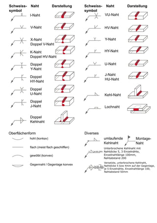
Schweissnahtsymbole kompakt BS499 / ISO 2553 vectorized
- 1. V-Naht Doppel J-Naht Doppel U-Naht Doppel HY-Naht Doppel Y-Naht K-Naht Doppel HV-Naht X-Naht Doppel V-Naht I-Naht Doppel Kehlnaht VU-Naht HV-Naht Y-Naht HY-Naht U-Naht J-Naht HU-Naht Lochnaht Kehl-Naht Schweiss- Naht Darstellung symbol Oberflächenform hohl (konkav) flach (meist flach geschliffen) gewölbt (konvex) Gegennaht / Gegenlage konvex Unterbrochene Kehlnaht mit Nahtdicke 5, 3 Einzelnähte, Einzelnahtlänge 100mm, Nahtabstand 200 Versetzte, unterbrochene Kehlnaht, Nahtdicke 5 bzw 4mm auf der Gegenlage, je 5 Einzelnähte, Einzelnahtlänge 100, Nahtabstand 50mm 5 5x100 (50) 4 5x100 (50) 5 3x100 (200) umlaufende Kehlnaht Montage- Naht Diverses Schweiss- Naht Darstellung symbol