Downloaden Sie, um offline zu lesen


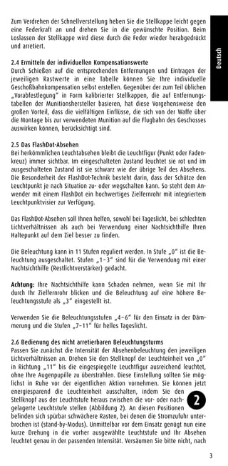
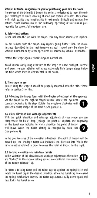
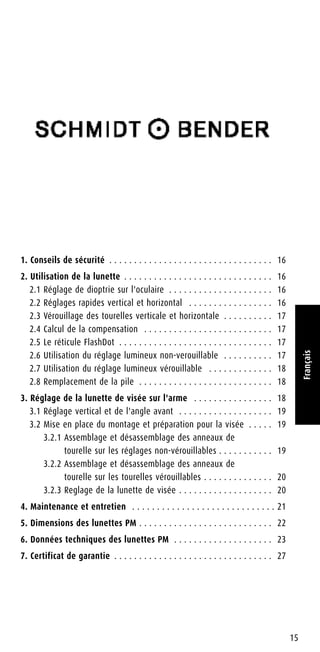
![Um den Höhenverstellweg in vollem Umfang nutzbar zu machen ist
es bei den PM-Modellen unerlässlich, bereits werksseitig das Absehen
außerhalb der optisch/mechanischen Mitte zu justieren (Abbildung 7).
Der Büchsenmacher ist deshalb gefordert, den von uns am Zielfernrohr
voreingestellten Wert an der Zielfernrohrmontage anzupassen. Das
bedeutet, das Zielfernrohr muss mit entsprechender Vorneigung auf
die Waffe montiert werden (Abbildung 8).
Mit dieser Einstellung kann nun der gesamte Verstellweg in einer Richtung
genutzt werden.
Ermitteln der Vorneigung
Die Vorneigung des Zielfernrohres ist abhängig von den verwendeten
Absehen-Schnellverstellungen. Bei Auslieferung werden die Absehen um die
Hälfte des Gesamtverstellbereiches der Schnellverstellung aus der Mitte
gestellt. Dieser Wert muß bei der Montage ausgeglichen bzw. berücksichtigt
werden.
Im Fachhandel finden Sie für jedes Schmidt & Bender PM-Zielfernrohr
Montagen bzw. Montageschienen, die dem jeweiligen Zielfernrohr entspre-
chend vorgeneigt sind.
Bestimmung der Vorneigung
Wenn die Stellkappe der Höhenschnellverstellung einen Gesamtverstellweg
von 26 MOA (Winkelminute; engl.: minute of angle) hat, benötigt Ihr
Zielfernrohr eine Vorneigung von 13 MOA (entspricht dem halben
Verstellbereich).
3.2 Vormontage und Vorbereitung zum Einschießen
Stellen Sie zunächst sicher, dass beide Stellkappen auf „0“ eingestellt sind.
Das Zielfernrohr wird nun montiert und mittels aller an der Montage gege-
benen Korrekturmöglichkeiten so genau auf ein 100 m entferntes Ziel aus-
gerichtet, dass bei der Feinjustierung während des Einschießens am
Zielfernrohr möglichst wenig Verstellweg verbraucht wird.
Zum Einschießen müssen die Stellkappen der Höhen- und Seiten-
schnellverstellung abgenommen werden. Wenn Ihr Zielfernrohr keine
arretierbaren Höhen- und Seitenstelltürme hat, verfahren Sie dazu nach
Punkt 3.2.1. Besitzt Ihr Zielfernrohr arretierbare Stelltürme, verfahren Sie
nach Punkt 3.2.2.
3.2.1 Demontage und Montage der Stellkappen bei nicht arretierbaren
Höhen- und Seitenelevationen
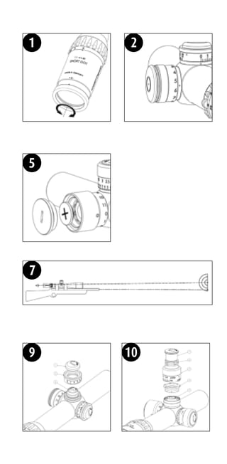
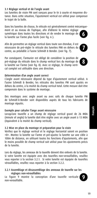
In Abbildung 9 wird der Aufbau nicht arretierbarer Stelltürme
dargestellt.
Demontage der Stellkappe
Lösen Sie mithilfe einer Münze die Elevationskappe [1] und entfernen sie
diese. Nehmen Sie die Stellkappe [2] ab. Mit einer Münze können nun am
Adapter [5] Höhen- bzw. Seitenkorrekturen der Treffpunktlage vorgenom-
men werden.
5
Deutsch
7
8
9](https://image.slidesharecdn.com/instructionsschmidtbenderpmdualuse-opticstrade-141218032716-conversion-gate02/85/Instructions-SCHMIDT-BENDER-PM-Dual-Use-Optics-Trade-11-320.jpg)
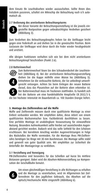
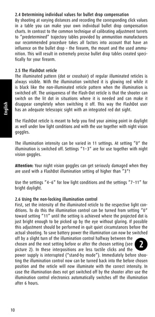
![Verwahren Sie während des Einschießens alle entfernten Bauteile an einem
sauberen Ort. Schmutz an den Bauteilen kann die Funktion beeinträchtigen
oder zu Undichtigkeiten führen.
Sie können die Waffe nun wie in Punkt 3.2.3 beschrieben einschießen und
anschließend diesen Abschnitt mit der Montage der Stellkappe fortsetzen.
Montage der Stellkappe nach dem Einschießen
Setzen Sie die Stellkappe auf den Stellturm. Richten Sie sie dabei so aus,
dass der Wert „0“ mit der Indexmarkierung am Sattel korrespondiert. Halten
Sie die Stellkappe fest, setzen Sie die Elevationskappe auf und schrauben
Sie sie mit einer Münze fest.
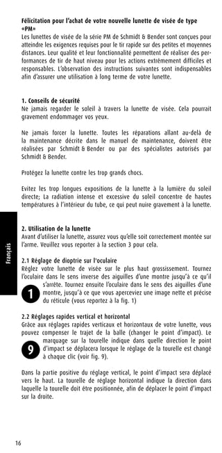
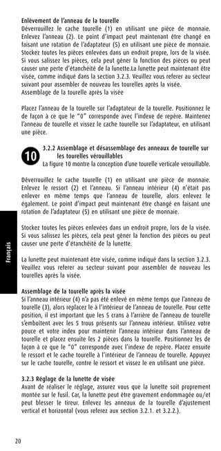
3.2.2 Demontage und Montage der Stellkappen bei arretierbaren
Höhen- und Seitenelevationen
In Abbildung 10 wird der Aufbau arretierbarer Stelltürme dargestellt.
Demontage der Stellkappe
Lösen Sie mithilfe einer Münze die Elevationskappe [1] und entfernen sie
diese. Nehmen Sie Feder [2] und Stellkappe [3] ab. Sollte der Rastring [4]
noch aufliegen, nehmen Sie auch diesen ab. Mit einer Münze können nun
am Adapter [5] Höhen- bzw. Seitenkorrekturen der Treffpunktlage vorge-
nommen werden.
Verwahren Sie während des Einschießens alle entfernten Bauteile an einem
sauberen Ort. Schmutz an den Bauteilen kann die Funktion beeinträchtigen
oder zu Undichtigkeiten führen.
Sie können die Waffe nun wie in Punkt 3.2.3 beschrieben einschießen und
anschließend diesen Abschnitt mit der Montage der Stellkappe fortsetzen.
Montage der Stellkappe nach dem Einschießen
Sollte der Rastring [4] noch nicht in der Stellkappe [3] sein, setzen Sie ihn
mit den fünf Bohrungen voran in die Unterseite der Stellkappe. Die fünf
Stifte in der Stellkappe müssen dabei in die Bohrungen des Rastrings passen.
Fassen sie mit einem Finger von oben durch die Stellkappe und halten Sie
den Rastring fest. Setzen Sie Stellkappe und Rastring auf den Stellturm.
Richten Sie die Stellkappe dabei so aus, dass der Wert „0“ auf der
Stellkappe mit der Indexmarkierung am Sattel korrespondiert. Legen Sie
Feder und Elevationskappe von oben in die Stellkappe. Drücken Sie entge-
gen der Federkraft die Elevationskappe nach unten und schrauben Sie sie
mit einer Münze fest.
3.2.3 Einschießen des Zielfernrohrs auf der Waffe
Vor dem Einschießen muss das Zielfernrohr ordnungsgemäß auf der Waffe
montiert sein. Andernfalls kann das Zielfernrohr beschädigt werden und es
besteht erhöhte Verletzungsgefahr für den Schützen. Demontieren Sie die
Stellkappen der Höhen- und Seitenelevation (Punkt 3.2.1 bzw. 3.2.2).
Nutzen Sie zum Einschießen möglichst eine justierbare Waffenauflage.
Legen Sie die Waffe auf, halten Sie mit dem Absehen auf die Zielmarke an
und setzen Sie einen Schuss. Schauen Sie sich das Schussbild durch Ihr
6
Deutsch
10](https://image.slidesharecdn.com/instructionsschmidtbenderpmdualuse-opticstrade-141218032716-conversion-gate02/85/Instructions-SCHMIDT-BENDER-PM-Dual-Use-Optics-Trade-12-320.jpg)
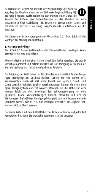
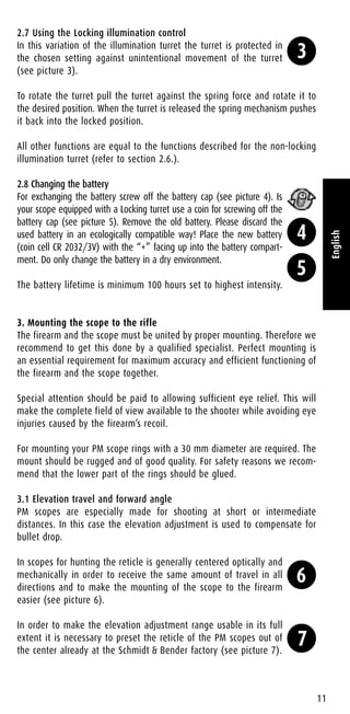
![As a consequence the gunsmith is obliged to consider the preset
position of the reticle in the elevation range when mounting the
scope to the firearm (see picture 8).
With this setup the full elevation range is usable in one direction.
Determining the correct forward angle
The necessary forward angle is depending on the used type of elevation
adjustment. At the Schmidt & Bender factory the reticles of PM scopes are
adjusted out of center by half the amount of the full elevation range. This
value must be compensated in the mount system.
Forward angled mounts or rails for every Schmidt & Bender PM scope type
are available from all renowned mount manufacturers.
Example for determining the required forward angle
When the turret has an engraved elevation range of 26 MOA (minute of
angle) the scope should be angled forward by 13 MOA (equalling half the
elevation range).
3.2 Preliminary mounting and preparation for sighting in
Make sure that both elevation and windage are set to “0”. Mount the scope
to the firearm and pre-adjust the scope to a target at 100m distance using
all adjustment facilities the mounts provide so that the least possible
amount of elevation range must be used at the scope for fine adjustment.
For sighting in the turret rings must be removed from the scope. If your
scope is equipped with non-locking turrets please refer to section 3.2.1.
Is your scope equipped with Locking turrets refer to section 3.2.2.
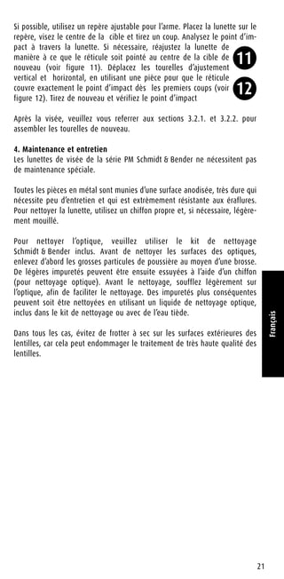
3.2.1 Removing and assembling the turret rings on non-locking
elevations
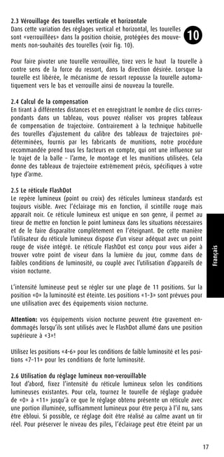
Picture 9 shows the design of a non-locking elevation turret.
Removing the turret ring
Unlock the turret cap [1] using a coin and remove it. Take the turret ring [2]
off. The point of impact can now be changed by rotating the adapter [5]
using a coin.
Store all removed parts in a clean place while sighting in. Dirt on the parts
may inhibit the function of the parts or may lead to leakage of the scope.
The rifle can now be sighted in as described in section 3.2.3. Please refer to
the following sector for assembling the turrets again after sighting in.
Assembling the turret after sighting in
Place the turret ring onto the turret adapter. Position it so that the “0”
corresponds with the index mark on the saddle. Hold the turret ring and
screw the turret cap onto the adapter using a coin.
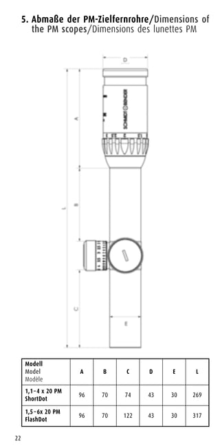
3.2.2 Removing and assembling the turret rings on Locking
turrets
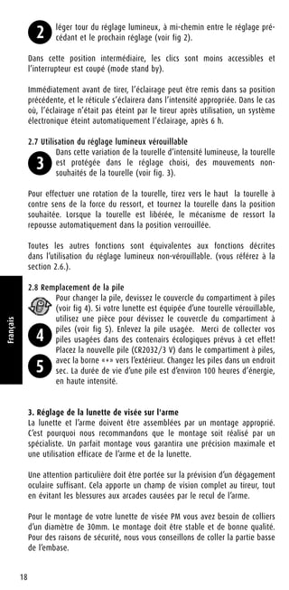
Picture 10 shows the design of a Locking elevation turret.
12
English
8
9
10](https://image.slidesharecdn.com/instructionsschmidtbenderpmdualuse-opticstrade-141218032716-conversion-gate02/85/Instructions-SCHMIDT-BENDER-PM-Dual-Use-Optics-Trade-18-320.jpg)
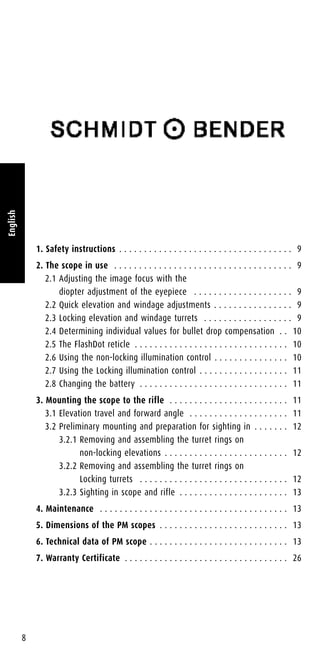
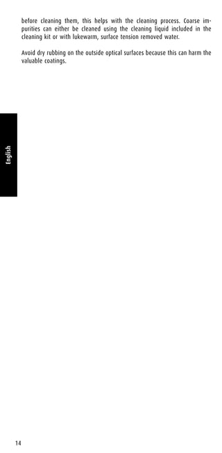
![Removing the turret ring
Unlock the turret cap [1] using a coin and remove it. Remove the spring [2]
and the turret ring. In case the inner click ring [4] was not removed toget-
her with the turret ring remove it as well. The point of impact can now be
changed by rotating the adapter [5] using a coin.
Store all removed parts in a clean place while sighting in. Dirt on the parts
may inhibit the function of the parts or may lead to leakage of the scope.
The rifle can now be sighted in as described in section 3.2.3. Please refer to
the following sector for assembling the turrets again after sighting in.
Assembling the turret after sighting in
Should the inner click ring [4] not have been removed together with the
turret ring [3] it must be placed in the turret ring again. For this position
it so that the 5 pins at the bottom of the turret ring engage with the 5 pin-
holes in the inner click ring. Use your thumb and index finger to hold the
inner click ring in the turret ring and palace both parts onto the turret.
Position them so that the “0” corresponds with the index mark on
the saddle. Place the spring and the turret cap in the turret ring. Press the
turret cap down against the spring and srew it in using a coin.
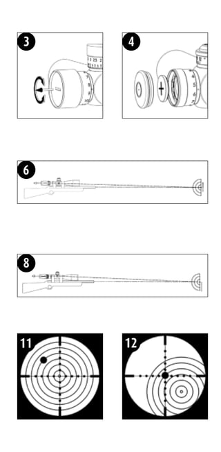
3.2.3 Sighting in scope and rifle
Before sighting in the scope must be properly mounted to the rifle.
Otherwise the scope can get seriously damaged and/or injuries of the user
might be caused. Remove the turret rings of windage and elevation adjust-
ments (refer to sections 3.2.1. and 3.2.2.).
If possible use an adjustable bearing for the rifle. Place the rifle on the
bearing, aim at the target center and fire a round(s). Analyze the
point(s) of impact through your scope. If necessary re-adjust the
rifle so that the reticle is aimed at the target center again. (see
picture 11). Move the elevation and windage turrets using a coin so
that the reticle exactly covers the point of impact from the first
round(s) (see picture 12). Shoot another round and check the point
of impact again. If necessary repeat these steps.
After sighting in refer to sections 3.2.1. and 3.2.2. for assembling the turrets
again.
4. Maintenance
Schmidt & Bender PM scopes do not require any special maintenance.
All metal parts have a hard anodized surface that is extremely scratch-resistant
and easy to care for. For cleaning use a clean and if necessary a slightly
damp cloth.
For cleaning the optics please use the included cleaning kit from
Schmidt & Bender. Before wiping the optic surfaces clean use a dry brush
for removing coarse dirt or dust particles. Slight impurities can then be
wiped of using an optics cleaning cloth. Breathe onto the optics surfaces
13
English
11
12](https://image.slidesharecdn.com/instructionsschmidtbenderpmdualuse-opticstrade-141218032716-conversion-gate02/85/Instructions-SCHMIDT-BENDER-PM-Dual-Use-Optics-Trade-19-320.jpg)


Die Bedienungsanleitung für das PM-Zielfernrohr bietet umfassende Informationen zur Sicherheit, Bedienung und Wartung des Geräts, einschließlich Details zur Installation und Ausrichtung auf der Waffe. Sie erklärt die Funktionen und Einstellungen, wie etwa die Anpassung der Bildschärfe und die Verwendung der verschiedenen Beleuchtungsmodi. Eine präzise Montage und korrekte Justierung sind unerlässlich für die optimale Nutzung und Sicherheit des Zielfernrohrs.


