LDPC - Low Density Parity Check Matrix
•Als PPTX, PDF herunterladen•
5 gefällt mir•4,560 views

The document describes an LDPC (Low Density Parity Check) codes project done by a group of students. Key points: - The group generated a sparse parity check matrix H for LDPC encoding that avoids cycles of length 4. - They implemented LDPC encoding in MATLAB and Verilog, calculating parity bits from the input message bits using the formula p = (B^-1) * (Au^T). - The Verilog implementation was tested on a Nexys-2 FPGA board, with input bits entered via switches and parity bits output to LEDs. - The project was completed over 8 weeks. While it demonstrated LDPC encoding, the group noted the encoder has high delay and

Empfohlen
Weitere ähnliche Inhalte
Was ist angesagt?
Was ist angesagt? (20)
Ähnlich wie LDPC - Low Density Parity Check Matrix
Ähnlich wie LDPC - Low Density Parity Check Matrix (20)
Mehr von Kavi
Mehr von Kavi (13)
Kürzlich hochgeladen
Kürzlich hochgeladen (20)
LDPC - Low Density Parity Check Matrix
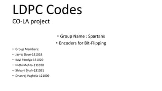
- 1. LDPC Codes CO-LA project • Group Name : Spartans • Encoders for Bit-Flipping • Group Members: • Jayraj Dave-131018 • Kavi Pandya-131020 • Nidhi Mehta-131030 • Shivani Shah-131051 • Dhanraj Vaghela-121009
- 2. INDEX • LDPC – INTRODUCTION • Encoding – Working Step-1(in Matlab) • Encoding – Working Step-2(in Matlab) • Encoding – Implementation in verilog • Encoding – Result on Isim and FPGA • Group Project Time-Line
- 3. LDPC • As their name suggests, LDPC codes are block codes with parity-check matrices • It contain only a very small number of non-zero entries(1’s). • It is the sparseness of H which guarantees both a decoding complexity which increases only linearly with the code length • and a minimum distance which also increases linearly with the code length.
- 4. LDPC – ENCODING In Matlab – Step -1 GENERATION OF PARITY CHECK MATRIX - H Generate ‘H’ Fill each column with 3 ones using ‘random’ function Detect the cycle of ‘4’ Flip the bits of the ‘rows’ that are Included in the cycle Parity Check Matrix (‘H’): -> The matrix to be created is of dimension 5K*10K, with the condition that each column has three ones in it avoiding cycle of 4. -> For this, we place three ones in each column at random positions using the randperm() function of Matlab. This results in every column having three ones. But it may also results in cycle of 4 and therefore we now detect them and remove them. ->To detect them we do the logical anding (and operation) of two rows and if the anding of two rows gives more than one one’s then the two rows result in cycle of 4. Thus we now detected the cycle of 4. ->We now identify the position within row that results in cycle of 4 after identifying the location we flip the bit within the row having maximum one. Thus we successfully remove the cycle of 4 and have created H matrix.
- 5. LDPC – ENCODING In Matlab – Step -2 CODE-WORD GENERATION - C Write H=[A | B] A & B are square Code Word C = [U | P] U = message bit P = parity bit HC^T = [A|B]|U^T| =0 |P^T | AU^T BP^T=0 p = (B^-1 AU^T) + C = [U | P] Supply ‘c’ to decoder CODE-WORD GENERATION (‘x’ or ‘c’): ->‘H’ is a rectangular matrix (m*2m) and therefore we write it as a combination of two square matrix ‘A’ (m*m) and ‘B’ (m*m), such that H = [A B]. ->Let ‘x’ be the codeword that is to be generated. Code – word consists of input bits (‘u’) and parity bits (‘p’), such that x = [u p]. ->Dimension of ‘x’ is 1*10K and that of ‘u’ and ‘p’ is 1*5K. Thus, to generate a code word we only need to know the parity bits (‘p’). ->Formula of Syndrome gives us the relation between ‘H’ and ‘x’ and it is: HxT = 0. Expanding the relation we get [A B]*[u p]T = 0. ->This on evaluating results in( AuT xor BpT )= 0 , and it finally leads to BpT = AuT. From the previous relation we get pT as pT = (B-1)* (AuT) and thus we get p as ((B-1)* (AuT))T. On knowing the parity bits, we can compute code word which is the augmentation of input bits(provided from client side) and parity bits(calculated above). Thus the codeword is now passed on to Decoders for the Module of Decoding – Decoding Partner: BLACK KNIGHT
- 6. LDPC – Encoding Implementation in Verilog • For Verilog H is of dimension 5x10 • With fixed H, we only need to compute parity Bits • Parity Bits formula same as before : p = ((B-1)* (AuT))T • B-1 is calculated in Matlab and used in Verilog • Made Matrix Multiplication Function in Verilog by calling Module within Module • Generated ucf file and implemented it on : NEXYS-2 FPGA • Take one input(of message Bits), provides two outputs (parity Bits- implemented on FPGA) and (Code word)
- 7. RESULT ON ISIM AND SIMULATOR
- 8. RESULT ON ISIM AND SIMULATOR MESSAGE BITS : 1 1 0 1 1 (Given through switches) PARITY BITS : 1 1 0 0 1 (Shown through Bulbs) CODE WORD : 1 1 0 1 1 – 1 1 0 0 1
- 9. CONCLUSION • LDPC was a great project to work with as it not only described the practical application of Linear Algebra in real life but we also came to know of how it works by programming it in MATLAB and implementing on FPGA. It was a hand on experience to develop a code that is widely used in the field of Signals, Systems and Communication Devices. • The project was done by us in the time-frame of 8-weeks. The main aim of the project in Encoding part was to develop large scale parity check matrix without cycle of-4 and at the completion we have developed the code that removes cycle of 4 and creates as sparse ‘H’ matrix as possible. Along with this accomplishment the system also suffers from one drawback. On removing the cycle of 4, we flip the bit and sometimes the flipping of bits reduces the column weight from 3 to 2. The System is also too slow as it takes lot of time to compute inverse of ‘B’. We also found some of the drawbacks of LDPC System as whole and have mentioned the same below: • LDPC have complex encoders, results in great delay to find inverse of the part of system (that is inverse of B). • LDPC code fails to deliver on small scale cases. • There are possible ways to counter the drawbacks; • Can devise a formula in which the there is no dependency on finding the invertible matrix. • Certain advantages of LDPC • (i). Randomly generated LDPC code has higher efficiency and fewer cycles then structurally or pattern-wise generated code. • (ii). The hardware implementation of LDPC Encoding is compact and easy to implement.