Performance Analysis, Designing and Testing 512 Bit Sram Memory Chip Using Xilinx/Modelsim Tool
•
0 gefällt mir•39 views

https://irjet.net/archives/V4/i1/IRJET-V4I1153.pdf

Empfohlen
Weitere ähnliche Inhalte
Was ist angesagt?
Was ist angesagt? (20)
Ähnlich wie Performance Analysis, Designing and Testing 512 Bit Sram Memory Chip Using Xilinx/Modelsim Tool
Ähnlich wie Performance Analysis, Designing and Testing 512 Bit Sram Memory Chip Using Xilinx/Modelsim Tool (20)
Mehr von IRJET Journal
Mehr von IRJET Journal (20)
Kürzlich hochgeladen
Kürzlich hochgeladen (20)
Performance Analysis, Designing and Testing 512 Bit Sram Memory Chip Using Xilinx/Modelsim Tool
- 1. International Research Journal of Engineering and Technology (IRJET) e-ISSN: 2395 -0056 Volume: 04 Issue: 01 | Jan -2017 www.irjet.net p-ISSN: 2395-0072 © 2017, IRJET | Impact Factor value: 5.181 | ISO 9001:2008 Certified Journal | Page 877 PERFORMANCE ANALYSIS, DESIGNING AND TESTING 512 BIT SRAM MEMORY CHIP USING XILINX/MODELSIM TOOL Monika Solanki Faculty, Dept. of Electronics and Telecommunication Engineering, MBM Engineering College, Rajasthan, India ---------------------------------------------------------------------***--------------------------------------------------------------------- Abstract - In this thesis a memory chip has been designed with the size of 512 bit using Xilinx or model sim software. Memory Built-in Self Test (MBIST) or as some refer to it array built-in self test is an amazing piece of logic. Without any direct connection to the outside world, a very complex embedded memory can be tested efficiently, easily and less costly. Modeling and simulation of MBIST is presented in this paper. The design architecture is written in Very High Speed Integrated Circuit Hardware Description Language (VHDL) code using Xilinx ISE tools. Verification of this architecture is carried out by testing stuck at fault SRAM. A BIST algorithms is implemented like March C- and many more to test the faulty SRAM. 1.INTRODUCTION Fast low power SRAMs are becoming the critical component of many VLSI chips. There is increasing divergence in the speed of the processors and the main memory, and the power dissipation is also increasing due to increase in the integration and the operatingspeedaswell asincreasein the battery powered devices. The SRAM helps in bridging the gap and also reducing the power dissipation.Afterdesigning the memory, we will go for testing the fault in the memory. 2. MEMORY TESTING Built-in self-test (BIST) technique is widely used to test and diagnose the random access memories (RAMs). To support the diagnosis, a BIST circuit exports the data tobediagnosed serially due to the limitation of test I/Os. Clearly, the diagnostic data exported is time consuming, because they are exported bit by bit. To reduce this time consumption, several diagnostic data compression techniques are there. Various compression methodsareproposedtocompress the data to be diagnosed in a pause and export way. Thus, BIST circuit is paused when fault is detected and then the fault is compressed and exported serially. 3. FAULT MODEL OF SRAM To Study the fault detection method of memory, we have to build fault models of memory first. There are three simplified parts where memory faults occur. The threeparts are: address decoder, read and write logic, memory cell array. The former two parts are equal to the latter in function; we only need to detect the memory cell array. Following are the types of faults also called fault model: Stuck-at Fault State Transition fault Coupling Fault Addressing Fault and Data retention Fault Stuck-at Fault: Abbreviated as SAF. In this type of fault model a unit or a line of memory is being assumed to be stuck at logical “1” or at logical “0”. State Transition fault: It is a part of stuck at fault, in which a unit or a line of memory that cannot achieve 0-1 or 1-0 conversion after a writing operation. These are called the rising state transition fault and falling state transition fault separately. Coupling Fault: It includes two units, one unit’s state changing causes the other’s unit’s state changing accordingly. Addressing Fault: In this type of fault model, a row or a column decoder may not access the addressing unit, or multiple addresses access the same storage unit, or one address accesses several cells simultaneously, or accessing other unit instead of the same specified unit. Stuck Open Fault: In this type of fault model, a storage unit cannot be addressed. If storage unit has only one input port, it will generate only a fixed output value. Data retention Fault: In this type of fault model, a storage unit cannot effectively keep its data value unchanged within specified time. 4. RAM BIST ARCHITECTURE The architecture of RAM BIST is shown below. In the first block of RAM BIST architecture “ROM based Algorithm Generator” has been shown in which all 8 algorithmarekept in an ideal state. This algorithm will remain in an ideal state Key Words: Built-in Self Test (BIST), StaticRandomAccess Memory (SRAM), Integrated Circuit (IC), Dynamic Random Access Memory (DRAM), VHSIC Hardware Description Language (VHDL).
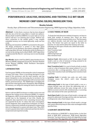
- 2. International Research Journal of Engineering and Technology (IRJET) e-ISSN: 2395 -0056 Volume: 04 Issue: 01 | Jan -2017 www.irjet.net p-ISSN: 2395-0072 © 2017, IRJET | Impact Factor value: 5.181 | ISO 9001:2008 Certified Journal | Page 878 unless BIST_EN signal is made equal to “1” (or it can be understood as until BIST_EN signal is made equal to “1”, the BIST operation would not be started). Among these 8 algorithms, one of the algorithms will be selecteddepending on the selection line of 8:1 MUX. Then selected algorithm is passed to “Algorithm Decoder”. The read/write signal from this block is transferred to the Embedded RAM to define weather read operationorwriteoperationwill be performed on to RAM Address. The up/down signal is passed to the “Address Generator” to define whether a Read / Write operation is performed in “Up addressing mode” or “Down addressing mode”, it is decided by selecting the algorithm operation. Fig -1: RAM BIST Architecture Then third signal Zero /One is passed to the “Data Generator” to define that read/write operationisperformed on “0” bit or “1” bit. Hence according to the state of selected algorithm, read/write operation is performedontotheRAM. Whenever “Read operation” performed then the data comes out of RAM and that data is transferred to the “Comparator”. In comparator there is another input port (that is test data) in which test input is given as same as that of data written onto “Embedded RAM”. The comparator will check that both inputs are same or not, if there is some fault on (like stuck at fault or coupling fault), then the output data coming out of “Embedded Memory”, is different from the input given in to the comparator. So it will show a fault by making “ fault detect” signal “equal to 1”, if there is no fault in memory then “fault detect” will be equal to the “0” On the other hand if “Write” is being performed then comparator will be in an ideal state. 5. ALGORITHM FOR RAM TESTING There are many types of test algorithms that are used for RAM testing. These algorithms are rather simple for BIST implementations. Table shown below includes various test algorithms for RAM testingalongwiththeinstructionswhich are performed by those algorithms. Table -1: ALGORITHMS FOR RAM TESTING No. Algorithm March Elements Code 000 MATS+ {↕(w0); ↑(r0,w1); ↓(r1,w0)} 001 March X {↕(w0); ↑(r0,w1); ↓(r1,w0), ↕(r0)} 010 March C- {↕(w0); ↑(r0,w1); ↓(r1,w0); ↕(r0,w1); ↓(r1,w0), ↕(r0)} 011 March A {↕(w0); ↑(r0,w1,w0,w1); ↑(r1,w0,w1); ↓(r1,w0,w1,w0); ↓(r0,w1,w0)} 100 March B {↕(w0); ↑(r0,w1,r1,w0,r0,w1); ↑(r1,w0,w1); ↓(r1,w0,w1,w0); ↓(r0,w1,w0)} 101 March U {↕(w0); ↑(r0,w1,r1,w0); ↑(r0,w1); ↓(r1,w0,r0,w1); ↓(r1,w0)} 110 March LR {↕(w0); ↓(r0,w1); ↑(r1,w0,r0,w1); ↑(r1,w0); ↑(r0,w1,r1,w0); ↑(r0)} 111 March SS {↕(w0); ↑(r0,r0,w0,r0,w1); ↑(r1,r1,w1,r1,w0); ↓(r0,r0,w0,r0,w1); ↓(r1,r1,w1,r1,w0); ↕(r0)} Among all these test algorithms, March C- algorithm is practical to offer the highest fault coverage. The capabilities of the fault detection of March test algorithms are summarized in Table below. All these test algorithms are planned for RAMs with one data bit per word, but the multiple bits per word can be appliedaswell.Toincreasethe fault detection rate, modification on the algorithm is required for sensitivity and coupling faults in RAM. Table -2:THESUMMARIZEDFAULTDETECTION OFMARCH TEST ALGORITHMS 6. SIMULATION RESULT There are various types of tools which can be used as a simulator for executing the step to test the design. This is done by the use of the test bench. A test bench is a set of the test stimuli timing corresponding to the circuit design. The response of the circuit which is undertestisthencanberead out in the form of waveforms. The test bench file is responsible for providing the input stimuli to the memory under test (MUT) like clock and various other test control signals. Then the response will be produced in terms of the failure signals which are detected ROM Based Algorit hm Generat or End_ BIS T BIS T_E n Fa ult / No Fa ult Tes t Inp ut Read/ Write M M C o d e Zero/ One Addr ess Up/D n Addr ess Mats Plus March- X C-minus March- A March- B March- U M U X 8: 1 Se le ct Alg orit hm Dec ode r March- LR March- SS Ad dre ss Gen erat or Emb edde d RA M Com parat or Data Gen erato r Out_ Data (7:0)
- 3. International Research Journal of Engineering and Technology (IRJET) e-ISSN: 2395 -0056 Volume: 04 Issue: 01 | Jan -2017 www.irjet.net p-ISSN: 2395-0072 © 2017, IRJET | Impact Factor value: 5.181 | ISO 9001:2008 Certified Journal | Page 879 and displayed in the form of waveforms. In this project we have used Model sim simulator. Theresult ofthedesigningis shown in the following section in the form of screenshots of the software. First of all we are showing the screenshot of the RTL schematic which is written in the Xilinx software. Fig -2: RTL schematic in Xilinx software For this the software first asks for the selection of the elements. After selecting the elements we have to click on the tab Create Schematic. As soon as we click on this tab, we see the RTL schematic of the program. Fig -3: Design summary in Xilinx software We can see all the details of the program in the design summary. The detail is shown in the form of table. This picture is shown in the following figure. Fig -4: Design summary in Xilinx software After doing all this we will simulate the VHDL code using the ISim simulator or modelsim software. The waveforms of all the input and output parametersaredisplayedonthescreen. We can then provide the input and observe the output. Fig -5: Waveform in Xilinx software The power report of the memory designed is shown below which will be obtained in the Xilinx Xpower analyzer.
- 4. International Research Journal of Engineering and Technology (IRJET) e-ISSN: 2395 -0056 Volume: 04 Issue: 01 | Jan -2017 www.irjet.net p-ISSN: 2395-0072 © 2017, IRJET | Impact Factor value: 5.181 | ISO 9001:2008 Certified Journal | Page 880 Fig -6: Power Analysis in Xilinx software Now after the overall designing and testing of the memory, we will connect it to the FPGA kit through Xilinx software. The screenshot is shown below: Fig -7: Connection with FPGA Figure 8: Connection with FPGA 7. CONCLUSION This paper presents the design of 512 bitSRAMmemory.We chose 6T SRAM as memory bit cell and made an array designed with that bit cell. We came to know many things about the low power implementation of this 6T SRAM by going through many papers like making a 7T SRAM or 8T SRAM. The work in this respect can be taken forward to make a low power implementation. We have grasped many important concepts and learned tools that will help us in future. In brief, a random access memory with built in self test has been successfully designed. The BIST techniquesaredivided as online and offline testing. This project is designed at the entry level of VHDL so there are lots of modifications that can be done and additional architecture can be added in order to increase the robustness of the design. March C- algorithm can be used in the design by simply modifying the decoder in our project. This is done because March C- algorithm is better able to cover the fault as compared to the otheralgorithms. We can increase the bit size so that more memory locations can be tested by us. BIST is not able to insert the fault model. So future work can be done in order to insert and then detect a set of fault models. We can reduce the hardware coverageofthe project by replacing the comparator and counter which we have used. Thus performance of our project will be improved. We can replace VHDL with Verilog HDL to reduce the command line for future work. Due to non availability of resources, we were not able to program this project into actual FPGA hardware. So the future works can be done to run all these testing through FPGA hardware device to verify our work. REFERENCES [1] Nor Zaidi Haron, Siti AisahMat Junos@Yunus and Amir Shah Abdul Aziz, “Modeling and Simulation of Microcode Memory Built-in Self Test Architecture for Embedded Memories”, Universiti Teknikal Malaysia Melaka. [2] Shivani Yadav, Neha Malik, Ashutosh Gupta and Sachin Rajput, “Low Power SRAM Design withReducedRead/Write Time,” International Journal ofInformationandComputation Technology, ISSN 0974-2239 Volume 3, Number 3 (2013), pp. 195-200. [3] Deepti Kanoujia, Vishal Moyal,“SurveyOnVariousWorks Done In Reducing Static Power In Various SRAM Cells”, International Journal Of Technology Enhancements and Emerging Engineering Research, Vol 2, Issue 11 ISSN 2347 – 4289.
- 5. International Research Journal of Engineering and Technology (IRJET) e-ISSN: 2395 -0056 Volume: 04 Issue: 01 | Jan -2017 www.irjet.net p-ISSN: 2395-0072 © 2017, IRJET | Impact Factor value: 5.181 | ISO 9001:2008 Certified Journal | Page 881 [4] Kalyana Srinivasa Rao, J Venkata Suman PG Student, Assistant Professor: Department of ECE, GMRIT, Rajam, Srikakulam, AP, “Low Power Design of A SRAM Cell for Embedded Memory”, International Journal of Research in Computer and Communication Technology, Vol 2, Issue 11, November- 2013. [5] Preeti S Bellerimath and R. M Banakar, “Implementation of 16X16 SRAM Memory Array using 180nm Technology”, International Journal of Current Engineering and Technology. [6] Chih-Sheng Hou, Jin-Fu Li, and Ting-Jun Fu, “A BIST Scheme with the Ability of Diagnostic Data Compression for RAMs”, IEEE Transactions on Computer-Aided Design of Integrated Circuits and Systems, Vol. XX. NO. XX, XXXX XXXX [7] Xu Chuanpei, Tao Yi, Wan Chunting, “BIST method of SRAM for network-on-chip”, School of Electronic Engineering and Automatic, Guilin University of Electronic Technology, Guangxi Key LaboratoryofAutomatic Detecting Technology and Instruments, Guilin 541004, China. [8] M.H. Husin, S.Y. Leong, M.F.M. Sabri, R. Nordiana,“Builtin self test for RAM Using VHDL”, Faculty of Engineering, Universiti Malaysia Sarawak 94300 Kota Samarahan, Sarawak. [9] Ad J. van de Goor, ComTex, Said Hamdioui, Halil Kukner, “Generic, Orthogonal and Low-cost March Element based Memory BIST”, Voorwillenseweg 201 2807 CA Gouda, The Netherlands and Delft University of Technology, Faculty of EE, Mathematics and CS, Mekelweg 4, 2628 CD Delft, The Netherlands. [10] Mária Fischerová, Martin Šimlaštík, “MemBIST Applet for Learning Principles of Memory Testing and Generating Memory BIST”, Institute of Informatics, Slovak Academy of Sciences. [11] Alberto Bosio, Luigi Dilillo, Patrick Girard, Arnaud Virazel, Leonardo B. Zordan, “An Effective BIST Architecture for Power-Gating Mechanisms in Low-Power SRAMs”, LIRMM, Montpellier, France. [12] Priyanka Gadde, Mohammed Niamat, “FPGA Memory Testing Technique using BIST”, Electrical Engineering and Computer Science Department, The University of Toledo 2801, W. Bancroft, Toledo, Ohio, USA. [13] P. Manikandan, Bjørn B Larsen, Einar J Aas, Mohammad Areef, “A Programmable BIST with Macro and Micro codes for Embedded SRAMs”, The NorwegianUniversityofScience and Technology, Norway and Juniper Networks, India. [14] Bharti Mishra, Dr. Rita Jain and Prof. Richa Saraswat, “Low Power BIST based Multiplier Design and Simulation using FPGA”, Department of ElectronicsandCommunication Engineering, LNCT, Rajiv Gandhi Technical University Bhopal, Madhya Pradesh, India.