This paper investigates behavior of the system in terms of time response e.g., steady state error, rise time & overshoot & then compare it with FLC. Being an unstable system, Inverted Pendulum is very common control problem being assigned to control its dynamics. It is almost impossible to balance a pendulum in the inverted position except applying some force from outside to the system.
Case Study of Various Parameters by Applying Swing Up Control for Inverted Pendulum
1. Indonesian Journal of Electrical Engineering and Informatics (IJEEI)
Vol. 3, No. 3, September 2015, pp. 167~171
ISSN: 2089-3272 167
Received January 9, 2015; Revised March 3, 2015; Accepted March 16, 2015
Case Study of Various Parameters by Applying Swing
up Control for Inverted Pendulum
Kunal Chakraborty*1
, Amit Kumar Sen2
, Rahul Dev Basak3
, Rahul Raushan4
1,3,4
Electrical Engineering Department, IMPS College of Engineering & Technology, Malda, India
2
Computer Science Department, IMPS College of Engineering & Technology, Malda, India
*Corresponding author, e-mail: kunalindian003@gmail.com
1
, amitsen41@gmail.com
2,
rahul1988.ee.imps@gmail.com
3
, rahulraushan2012@gmail.com
4
Abstract
This paper investigates behavior of the system in terms of time response e.g., steady state error,
rise time & overshoot & then compare it with FLC. Being an unstable system, Inverted Pendulum is very
common control problem being assigned to control its dynamics. It is almost impossible to balance a
pendulum in the inverted position except applying some force from outside to the system.
Keywords: inverted pendulum, swing up control, nonlinear control, PID controller, FLC controller
1. Introduction
In this problem, the pendulum is first placed in upright position, i.e., in a position of
unstable equilibrium, or it is given some initial displacement. The controller is then switched in to
balance the pendulum and to maintain this balance in the presence of disturbances. A normal
disturbance may be a tap on the balanced pendulum. An inverted pendulum is a classic control
problem. The process is non linear and not stable with single input signal and many output
signals. Our aim is to balance the pendulum vertically on a wagon which is run by motor. The
following figure shows an inverted pendulum. The target is to move the wagon along the x
direction to a required point without letting the pendulum fall. The wagon, which is run by a DC
motor, is controlled by a controller (in our implementation which is analog in nature). The x
position of the wagon and the pendulum angle θ are measured and fed to the control system. A
force which creates disturbance can be applied on top of the pendulum.
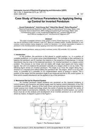
2. Mechanical Set Up for Physical System
An inverted pendulum based problems are renowned as the classical problems in
control systems and dynamics and being hugely used for testing control philosophy of the PID
controllers and SFB etc. Balance of the motor driven cart and pendulum has internal relation to
rocket science and missile technology where the centre of gravity lies beneath the centre of
drag which leads to aerodynamic instability. For a real example of control system, our current
focus must be on the analysis and development of an inverted pendulum on a cart which is
driven by motors. A diagram is given in the Figure 1.
Figure 1. The Pendulum System
2. ISSN: 2089-3272
IJEEI Vol. 3, No. 3, September 2015 : 167 – 171
168
For studying the whole model in a proper way, the mathematical model is very much helpful. In
this paper the mathematical model of the system can be found with the help of Euler-Lagrange’s
equation. The resultant non-linear model is made linear then, after that the cart combining with
an inverted pendulum, given below is done with an impulse force F. The dynamic equation of
motion is made linear with the pendulum angle theta. The physical data [9] of the system are
given in Table 1.
Table1. Parameters of the system from feedback instrument .U.K.
Parameter Value Unit
Cart mass(M) 0.815 Kilo gram
Mass of the pendulum(m) 0.210 Kilo gram
Length of pendulum(L) 0.305 Meter
Coefficient of frictional force(B) 0.005 Ns/m
Pendulum damping coefficient(D) 0.005 Mm/ radian
Moment of inertia of pendulum(I) 0.099 Kg/
Gravitation force(G) 9.8 m/
3. Mathematical Equation of the System
The Lagrangian equation of the entire system is given as:
L= (m 2
+2ml cos +ml2 2
+M 2
)+ I 2
]-mglcos
The Euler-Lagrange’s equation for the cart &resultant system is given as:
0
Using these two above equations and putting the system parameters value we get:
cos sin 0
cos sin
The above equation shows the dynamics of the system.
4. Linearization of the Equation
When pendulum is in upright position sin , cos 1, 0 Using above relation
we can write as, To obtain the transfer function of the linear system equations analytically, we
must first take the Laplace transform of the system equations. The Laplace transforms are:
(M +m) X(s) s2
+ q X(s)s+ q θ(s) s2
= F(s)
(I +ml 2
)θ(s) s2
- k θ(s) + q X(s) s2
=0
Now it becomes:
r +q -k +d =0
Where, (M+m)= p, mgl=k, ml=q, I+ml2
=r
5. Transfer Function Modelling
After taking Laplace transform of linear differential equation we get the following T.F.
model:
3. IJEEI ISSN: 2089-3272
Case Study of Various Parameters by Applying Swing Up Control for… (Kunal Chakraborty)
169
[Angle T.F.] (1)
So Equation (1) may be rearrange as:
=
.
. . . .
&
[Cart T.F.] (2)
. . .
. . . .
6. MATLAB Simulation
Figure 2.Simulink Diagram of PID & FLC Controller
7. Simulation Result
Figure 3. Response For FLC Controller Figure 4. Response of PID Controller For
angle
4. ISSN: 2089-3272
IJEEI Vol. 3, No. 3, September 2015 : 167 – 171
170
Figure 5. Response of PID Controller For cart
8. Comparison of Various Parameters
Table 2 indicates the comparison between various parameters of PID & FLC Controller.
Table 2. Comparison of Various Parameters
Parameter FLC PID
Overshoot Less More
Rise Time More Less
Settling Time Less More
Transient Not Present Present
9. Conclusion
Simulation of inverted pendulum using different controller set up shows that system is
unstable with non-minimum phase zero. Unlike the conventional PID controller the Fuzzy Logic
Controller has some benefits on the system response .It has been seems that FLC using a few
number of rules and straightforward implementation used to solve a classical control problems
with unknown dynamics. As a future work one can develop design a FLC Controller for double
beam inverted pendulum.
Acknowledgements
We are highly thankful to Mr. Bablu Bhattacharjee, chairman, IMPS college of
engineering and technology, Malda, Dr. Salil kumar Bhattacharjee, Principal, IMPS college of
engineering and technology, Malda to provide us lab facilities so that we can carry out our work.
We also very thankful to Dr.Bishnu Pada Sarkar, Director, IMPS college of engineering and
technology, Malda for his valuable suggestion regarding research work publication.
References
[1] HJT Smith. Experimental study on inverted pendulum in April 1992. IEEE. 1991.
[2] Alan Bradshaw, Jindi Shao. Swing-up control of inverted pendulum systems. Robotica. 1996; 14: 397-
405.
[3] Elmer P Dadios. Fuzzy Logic – Controls, Concepts, Theories and Applications. First Edition. Janeza
Trdine 9, 51000 Rijeka, Croatia. 2012: 428.
[4] Mario E Magana, Frank Holzapfel. Fuzzy –Logic Control of an inverted pendulum with Vision
Feedback. IEEE transactions on education. 1998; 41(2): 1998.
[5] KJ Astrom, K Furuta. Swinging up a pendulum by energy control. Automatic 36. 2000: 287-295.
[6] Feedback instrument. U.K.
[7] IJ Nagrath, M Goplal. Control Systems Engineering. Fourth edition. 1975.
[8] Ogata. Modern Control Engineering. Fourth Edition. 2006.
[9] Kyung-Jae Ha, Hak-Man Kim. A Genetic Approach to the Attitude Control of an inverted pendulum
system. IEEE. 1997.
[10] Felix Grasser, Aldo D’Arrigo, Silvio Colombi, Alfred C Rufer. JOE: A Mobile, Inverted Pendulum. IEEE
transactions on industrial electronics. 2002; 49(1).
5. IJEEI ISSN: 2089-3272
Case Study of Various Parameters by Applying Swing Up Control for… (Kunal Chakraborty)
171
[11] Zdenko Kovaˇci, Stjepan Bogdan. Fuzzy Controller Design Theory and Applications. CRC Press
Taylor & Francis Group. 2006: 392.
[12] User's Guide of Matlab for Fuzzy Logic Toolbox. 2012.
[13] SN Sivanandam, S Sumathi, SN Deepa. Introduction to Fuzzy Logic using MATLAB. Springer-Verlag
Berlin Heidelberg. 2007: 441.
[14] Laxmidhar Bhera, Indrani Kar. Intelligent Systems and Control. 2nd edition. 2010.
[15] Co Tomas B. Ziegler Nichols Method. Michigan Technological University Department of Chemical
Engineering Website. URL: http://www.chem.mtu.edu/~tbco/ cm416/zn.html (cited February 3, 2010).
![ ISSN: 2089-3272
IJEEI Vol. 3, No. 3, September 2015 : 167 – 171
168
For studying the whole model in a proper way, the mathematical model is very much helpful. In
this paper the mathematical model of the system can be found with the help of Euler-Lagrange’s
equation. The resultant non-linear model is made linear then, after that the cart combining with
an inverted pendulum, given below is done with an impulse force F. The dynamic equation of
motion is made linear with the pendulum angle theta. The physical data [9] of the system are
given in Table 1.
Table1. Parameters of the system from feedback instrument .U.K.
Parameter Value Unit
Cart mass(M) 0.815 Kilo gram
Mass of the pendulum(m) 0.210 Kilo gram
Length of pendulum(L) 0.305 Meter
Coefficient of frictional force(B) 0.005 Ns/m
Pendulum damping coefficient(D) 0.005 Mm/ radian
Moment of inertia of pendulum(I) 0.099 Kg/
Gravitation force(G) 9.8 m/
3. Mathematical Equation of the System
The Lagrangian equation of the entire system is given as:
L= (m 2
+2ml cos +ml2 2
+M 2
)+ I 2
]-mglcos
The Euler-Lagrange’s equation for the cart &resultant system is given as:
0
Using these two above equations and putting the system parameters value we get:
cos sin 0
cos sin
The above equation shows the dynamics of the system.
4. Linearization of the Equation
When pendulum is in upright position sin , cos 1, 0 Using above relation
we can write as, To obtain the transfer function of the linear system equations analytically, we
must first take the Laplace transform of the system equations. The Laplace transforms are:
(M +m) X(s) s2
+ q X(s)s+ q θ(s) s2
= F(s)
(I +ml 2
)θ(s) s2
- k θ(s) + q X(s) s2
=0
Now it becomes:
r +q -k +d =0
Where, (M+m)= p, mgl=k, ml=q, I+ml2
=r
5. Transfer Function Modelling
After taking Laplace transform of linear differential equation we get the following T.F.
model:](data:image/gif;base64,R0lGODlhAQABAIAAAAAAAP///yH5BAEAAAAALAAAAAABAAEAAAIBRAA7)