Analysis of diagrid structure in comparison with exterior braced frame structure

Abstract Over the last 10 years, diagrid structures have proven to be highly adaptable in structuring a wide range of building types, spans and forms. In most applications, diagrids provide structural support to buildings that are non rectilinear, adapting well to highly angular buildings and curved forms. The origin of the diagrid structural technology lies at the crossroads of engineering and architecture. The term “diagrid” have come from perimeter diagonals which have good structural efficiency and is gaining new interests in designing of tall structures because of its lattice like look. The term “diagrid” is a blending of the words “diagonal” and “grid” and refers to a structural system that gains its structural integrity through use of triangulation. In the diagrid structures, the vertical columns from the periphery are eliminated and this constructs the main difference between diagrids and exterior braced frames. Having triangulated configuration, the diagrids are able to carry the gravity and lateral loads. They also effectively minimize shear deformation as the diagonals carry the loads axially. The diagrid structural system is adopted these days for tall buildings because of its stiffness and flexibility in the architectural planning. This paper presents the study of 20- storey diagrid structure in comparison with exterior braced frame structure.Analysis results and design of both the models are presented in terms of storey shear, displacement, drift and summary of lateral and gravity forces. KeyWords:Diagrid structure, Exterior braced frame structure, Storey displacement, and Storey drift

Empfohlen
Empfohlen
Weitere ähnliche Inhalte
Was ist angesagt?
Was ist angesagt? (20)
Andere mochten auch
Andere mochten auch (18)
Ähnlich wie Analysis of diagrid structure in comparison with exterior braced frame structure
Ähnlich wie Analysis of diagrid structure in comparison with exterior braced frame structure (20)
Mehr von eSAT Journals
Mehr von eSAT Journals (20)
Kürzlich hochgeladen
Kürzlich hochgeladen (20)
Analysis of diagrid structure in comparison with exterior braced frame structure
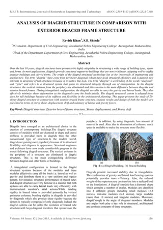
- 1. IJRET: International Journal of Research in Engineering and Technology eISSN: 2319-1163 | pISSN: 2321-7308 _______________________________________________________________________________________ Volume: 04 Issue: 12 | Dec-2015, Available @ http://www.ijret.org 156 ANALYSIS OF DIAGRID STRUCTURE IN COMPARISON WITH EXTERIOR BRACED FRAME STRUCTURE Ravish Khan1 , S.B. Shinde2 1 PG student, Department of Civil Engineering, Jawaharlal Nehru Engineering College, Aurangabad, Maharashtra, India 2 Head of the Department, Department of Civil Engineering, Jawaharlal Nehru Engineering College, Aurangabad, Maharashtra, India Abstract Over the last 10 years, diagrid structures have proven to be highly adaptable in structuring a wide range of building types, spans and forms. In most applications, diagrids provide structural support to buildings that are non rectilinear, adapting well to highly angular buildings and curved forms. The origin of the diagrid structural technology lies at the crossroads of engineering and architecture. The term “diagrid” have come from perimeter diagonals which have good structural efficiency and is gaining new interests in designing of tall structures because of its lattice like look. The term “diagrid” is a blending of the words “diagonal” and “grid” and refers to a structural system that gains its structural integrity through use of triangulation. In the diagrid structures, the vertical columns from the periphery are eliminated and this constructs the main difference between diagrids and exterior braced frames. Having triangulated configuration, the diagrids are able to carry the gravity and lateral loads. They also effectively minimize shear deformation as the diagonals carry the loads axially. The diagrid structural system is adopted these days for tall buildings because of its stiffness and flexibility in the architectural planning. This paper presents the study of 20- storey diagrid structure in comparison with exterior braced frame structure.Analysis results and design of both the models are presented in terms of storey shear, displacement, drift and summary of lateral and gravity forces. KeyWords:Diagrid structure, Exterior braced frame structure, Storey displacement, and Storey drift --------------------------------------------------------------------***---------------------------------------------------------------------- 1. INTRODUCTION Diagrids have emerged as an architectural choice in the creation of contemporary buildings.The diagrid structure consists of modules which are diamond in shape and lateral stiffness is provided more in diagrids than the other conventional type of structures.In the modern world, diagrids are gaining more popularity because of its structural flexibility and elegance in appearance. Structural engineers and architects have now made considerable progress in the trends following diagrid structures. The vertical columns in the periphery of a structure are eliminated in diagrid structures. This is the main extinguishing difference between diagrids and other forms of buildings. A triangulated configuration is formed in the diagrid structural systems because of the modules and these modules effectively carry all the loads i.e. lateral as well as gravity and distribute them in a very uniform and regular pattern. For instance, structural performance of braced tubes and diagrid structures are very familiar in a manner that both systems are able to carry lateral loads very efficiently with theirstructural member’s axial actions.While bending rigidity in braced tubes is provided primarily by vertical perimeter columns, bending rigidity in diagrids is provided by diagonals which also provide shear rigidity because the system is typically composed of only diagonals. Indeed, the diagrid systems can be called the evolution of braced tube structureswith large-diagonal members that spread over the periphery. In addition, by using diagonals, less amount of material is used. Also, due to elimination of columns, much space is available to make the structure more flexible. (a) (b) Fig -1: (a) Diagrid building, (b) Braced building Diagrids provide increased stability due to triangulation. The combination of gravity and lateral load bearing systems potentially provides more efficiency. Also, the reduced weight of the superstructure can translate into a reduced load on the foundations. A diagrid’s module has a diamond shape which contains a number of stories. Modules are classified into 4 different groups including small modules (2-4 stories), mid-size modules (6-8 stories), large modules (more than 10 stories) and irregular modules. Moreover, diagrid’sangle is the angle of diagonal members. Modules and angles both play a key role in structural, architectural and aesthetic concepts of these structures.
- 2. IJRET: International Journal of Research in Engineering and Technology eISSN: 2319-1163 | pISSN: 2321-7308 _______________________________________________________________________________________ Volume: 04 Issue: 12 | Dec-2015, Available @ http://www.ijret.org 157 The first diagrid supported building stands along the development timeline, the IBM building, now called the United Steelworkers Building, and was completed in 1963 in Pittsburgh. Other great examples of diagrid buildings are Hearst Tower in USA, Swiss Re in London, Poly International Plaza in China, CCTV Tower in China, etc. (a) (b) (c) Fig -2: (a) TornadoTower- Qatar, (b)The Bow Tower- Canada, (c)Poly International Plaza- China 2. METHODOLOGY 2.1 Analysis and Building Configuration of the Structural Models Two structural models are taken in account for this study, which is diagrid model and braced frame model. Following data are involved in the modeling of both the structures: 1) 20-storey building with 18x18m plan dimension, having 72m of total height with 3.6m height of each storey is taken for both models. 2) The slab thickness is taken 120mm for both models. 3) Size of diagrid is taken 350mm pipe section with 12mm thickness at an angle of 67.4°. 4) For braced frame model, inverted V-type bracings are used which is long leg back to back double angle section of 180x180x15mm. 5) The revised sizes of beams and columns after design are given in table -4. 6) The dead load is taken 5.5kN/m2 on terrace level and 4kN/m2 on floor level. The live load is taken 1.5kN/m2 on terrace level and 4kN/m2 on floor level of both the models. 7) The earthquake load parameters are taken as zone factor 0.1, soil type II, Importance factor 1, Response Reduction 5 as per IS-1893-2002. 8) The wind loadsare computed based on location Aurangabad, Wind speed 39 m/s, Terrain category 2, Structureclass B, Risk Coefficient 1, Topography factor 1. 9) Supports are taken fixed. Hinged condition is applied to diagrids. 10) Modeling, analysis and design is carried out on STAAD.Pro V8isoftware and the design of columns are done by IS-456-2000 and that of beams, diagrids and bracings are done by IS 800- 2007. (a) (b) (c) Fig -3: (a) Plan for both models (b) Elevation of diagrid model (c) Elevation of braced frame model 2.2 Distribution of loads in the structural models Lateral loads due to wind and earthquake and gravity load are the two main types of loads acting on the structural models. From the analysis, it is found that amount of wind load is greater than earthquake load and hence, wind load dominates in the design of both the structural models. The amount of lateral load in both the models is shown in table – 1.
- 3. IJRET: International Journal of Research in Engineering and Technology eISSN: 2319-1163 | pISSN: 2321-7308 _______________________________________________________________________________________ Volume: 04 Issue: 12 | Dec-2015, Available @ http://www.ijret.org 158 Table -1: Lateral loading Type of loading Load on Diagrid Frame (KN) Load on Braced Frame (KN) Earthquake in X- direction 7,656 9,964 Earthquake in Z- direction 7,656 9,964 Wind in X-direction 30,514 71,646 Wind in Z-direction 30,514 71,646 The gravity load and lateral load distribution in exterior frame and interior frame of both the models is shown in table -2. Table -2: Load distribution Diagrid building Braced building Total loading (KN) Loadin g on Interior frame (KN) Loadin g on Exterio r frame (KN) Total loading (KN) Loadin g on Interior frame (KN) Loadin g on Exterio r frame (KN) Gravity loading 107,596 64,972 42624 119,383 48,852 70,531 Lateral loading 30,378 5774 24,604 71,638 4874 66,764 Fig -4 shows the percentage of loading carried by exterior and interior frames of both the models. It is observed that in both the structures, exterior frame take maximum amount of lateral load whereas, interior frame in diagrid model takes more gravity load and in braced model, exterior frame takes more gravity load. It also shows that, the Diagrid structure is capable to take the almost same amount of lateral loading on its exterior frame as compared to the braced structure, despite that all the vertical columns in the periphery are eliminated in the Diagrid structure. 2.3 Analysis Results The results of analysis are in terms of displacement of the stories, inter storey drift, storey shear and are presented in this paper. The storey shear of diagrid model and braced model are shown in fig -5. The distribution of storey shear in diagrid structure is less than braced frame structure, as seen in the analysis results.The strorey displacement of diagrid model and braced frame model is shown in table -3. It is noted that top strorey displacement of diagrid structure in wind load case is less as compared to that of braced frame structure.The displacement and inter storey drift of diagrid model and braced frame model is shown in fig -6 and fig - 7.It is observed that top strorey displacement and drift of braced structure is more than diagrid structure. Fig -4: Distribution of loads in exterior and interior frame of both structural models Table -3: Displacement results . Load case Diagrid building Braced building Permissible value Top storey displacement WLX/WLZ 64.4mm 120.8mm 144mm Storey drift WLX/WLZ 2.7mm 3.9mm 14.4mm Fig -5: Storey shear v/s storey Fig -6: Displacement v/s storey
- 4. IJRET: International Journal of Research in Engineering and Technology eISSN: 2319-1163 | pISSN: 2321-7308 _______________________________________________________________________________________ Volume: 04 Issue: 12 | Dec-2015, Available @ http://www.ijret.org 159 Fig -7: Drift v/s storey 2.4 Design of Diagrid Structure and Braced Structure The design of both the structural models is carried out using STAAD.Pro V8i software. The dead, live, earth quakeand wind load and all load combinations are applied to the models. The design of diagrid members, braced angle members and all beams are designed as per IS 800-2007 and all the columns are designed as per IS 456-2000. The characteristic compressive strength of concrete is taken 30 N/mm2 and for steel is 415 N/mm2 . The yield stress of steel is taken 250 N/mm2 and the ultimate tensile strength is 420 N/mm2 . The final sizes of members which are obtained from the analysis for both the structures are given in the table-4. Table -4: Sizes of structural members for both models Member Memb er no. Diagrid building Braced building Property Beam B ISMB500 ISMB500 Steel Column C1 600x600mm 500x500mm Concrete C2 700x700mm 600x600mm Diagrid D1 350mm pipe with 12mm thickness _ Steel Bracing b1 _ ISA 180x180x15 LD Steel 2.5 Material Consumption The quantity of concrete and steel required is calculated for both the buildings. It is noted that the consumption of concrete for braced frame model is more than the diagrid model by 30%. Whereas the consumption of steel is 6% more in diagrid structure as compared to braced frame model. This is shown in fig -8 and fig -9. Fig -8: Concrete Consumption Fig -9: Steel Consumption 3. CONCLUSIONS From the study, it is concluded that, The diagrid structure resists approximately the same amount of lateral loads as compared to the exterior braced structure, despite all the vertical columns being eliminated in the periphery of the diagrid structure. Diagrid structure provides more efficiency than braced structure. Also, less amount of storey shear is seen in diagrid structure than to the braced frame structure. The top storey drift of diagrid structure is less by 30.7% than in the exterior frame structure. The top storey displacement of diagrid structure is less by 46.7% than in the exterior frame structure. All these factors make the diagrid structure more resistant than the braced frame structure. Diagrid structure gives more aesthetic look and gives more of interior space due to less columns and façade of the building can also be planned more efficiently. ACKNOWLEDGEMENT I would like to acknowledge the support of my guide Dr. S.B. Shinde for guiding me through this work and also grateful to Jawaharlal Nehru Engineering College for contributing me the platform and opportunity to accomplish my work. I would also like to extend my thanks to all those who offered me collegial guidance and support.
- 5. IJRET: International Journal of Research in Engineering and Technology eISSN: 2319-1163 | pISSN: 2321-7308 _______________________________________________________________________________________ Volume: 04 Issue: 12 | Dec-2015, Available @ http://www.ijret.org 160 Author’s Photo REFERENCES [1]. Mir M. Ali and Kyoung S. Moon, “Structural Developments in Tall Buildings: Current Trends and Future Prospects”, Architectural Science Review, vol. 50.3, pp 205- 223, 2007. [2]. Kyoung S. Moon, “Diagrid Structures for Complex- Shaped Tall Building”, Published by Elesevier Ltd, Procedia Engineering 14, pp 1343-1350,2011. [3]. Khushbu Jani and Paresh V. Patel, “Analysis and Design of Diagrid Structural System for High Rise Steel Buildings”, Published by Elesevier Ltd, Procedia Engineering 51, pp 92-100,2013. [4]. Kyoung S. Moon, Jerome J. Connor and John E. Fernandez, “Diagrid Structural Systems for Tall Building: Characteristics and Methodology for Preliminary Design”, Willey Interscience Publication. [5].J. Kim, Y.Jun and Y.-Ho Lee, “Seismic Performance Evaluation of Diagrid System Buildings”, 2nd Specially Conference on Disaster Mitigation, Manitoba, 2010. [6].Charnish B. and McDonnell T. “The Bow: Unique Diagrid Structural System for a Sustainable Tall Building”, CTBUH 8th World Congress, Dubai. [7].Nishith B. Panchal, Vinubhai R. Patel, “Diagrid Structural System: Strategies to Reduce Lateral Forces on High-Rise Buildings”, International Journal of Research in Engineering and Technology, vol. 03, pp 377-378, 2014. [8].Rohit kumar Singh, Vivek Garg, Abhay Sharma, “Analysis and Design of Concrete Diagrid Building and its comparison with Conventional Frame Building”, International Journal of Science, Engineering and Technology, vol. 02, pp 1330-1337, 2014. [9].Nishith B. Panchal, Vinubhai R. Patel, I.I. Pandya, “Optimum Angle of Diagrid Structural System”, International Journal of Engineering and Technical Research, vol. 02, pp 150-157, 2014. [10]. IS: 800-2007. General Construction in Steel- Code of Practice (Third Revision), Bureau of Indian Standard, New Delhi [11]. IS: 456-2000. Plain and Reinforced Concrete- Code of Practice (Fourth Revision), Bureau of Indian Standard, New Delhi. [12]. IS: 1893(Part-I)-2002, Criteria for Earthquake Resistant Design of Structures, Bureau of Indian Standard, New Delhi. [13]. IS: 875(Part-I, II, III)-1987, Code of Practice for Design Loads (other than Earthquake) for Buildings and Structures, Bureau of Indian Standard, New Delhi. BIOGRAPHIES I am Ravish H. Khan. I am pursuing my masters in structural engineering from Jawaharlal Nehru Engineering College, Aurangabad. I am doing my dissertation work under the guidance of Dr. S. B. Shinde (Head of the Department). Dr. S. B. Shinde is the Head of the Department of Civil Engineering Department, Jawaharlal Nehru Engineering College, Aurangabad. She has completed her Ph.D. in structural engineering in the year 2013.She has a total experience of 15 years in the civil engineering department.