An experimental investigation on flexural behaviour of fibre reinforced robo sand ferrocement

Abstract Now a days due to many civil engineering constructions through out the globe the usage of natural sand is very large and so it is slowly becoming scarce. Because of this main reason in the present days the usage of Robo sand or Crushed or artificial sand has gained momentum. This paper presents a brief study on the flexural behaviour of fibre reinforced ferrocement elements made with artificial sand(Robo sand).Nearly 30 mortar cubes and 180 flexural specimens were cast and tested with the variables such as different percentages of steel fibre, number of wire mesh layers and different span to depth ratios (a/d) etc,. From the results it is observed that with the increase in percentage of fibres the compressive strength of mortar, first crack load, ultimate load in flexure, flexural stress at first crack load, flexural stress at ultimate load and energy absorption increase up to certain extent and afterwards get decreased. Also the above strength parameters are found to increase with number of wire mesh layers. More so the above strengths are found to decrease with the increase in a/d ratio except the flexural stresses at first crack load and ultimate load. Besides the paper presents the behaviour of load – deflection variation and crack pattern for number of variables studied. Further a comparative study of the behaviour of robo sand specimens with those of the natural sand has been studied. Finally an analytical model has been proposed for Mcr and Mu with the inclusion of the most of the variables used in the present investigation. Keywords: Robosand, Span to Depth ratio (a/d), Volume percentage of fibres (Vf), Number of Mesh Layers (N).

Empfohlen
Empfohlen
Weitere ähnliche Inhalte
Was ist angesagt?
Was ist angesagt? (20)
Andere mochten auch
Ähnlich wie An experimental investigation on flexural behaviour of fibre reinforced robo sand ferrocement
Ähnlich wie An experimental investigation on flexural behaviour of fibre reinforced robo sand ferrocement (20)
Mehr von eSAT Journals
Mehr von eSAT Journals (20)
Kürzlich hochgeladen
Kürzlich hochgeladen (20)
An experimental investigation on flexural behaviour of fibre reinforced robo sand ferrocement
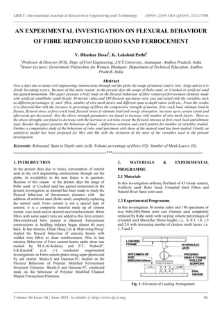
- 1. IJRET: International Journal of Research in Engineering and Technology eISSN: 2319-1163 | pISSN: 2321-7308 _______________________________________________________________________________________ Volume: 04 Issue: 06 | June-2015, Available @ http://www.ijret.org 85 AN EXPERIMENTAL INVESTIGATION ON FLEXURAL BEHAVIOUR OF FIBRE REINFORCED ROBO SAND FERROCEMENT V. Bhaskar Desai1 , K. Lakshmi Pathi2 1 Professor & Director (ICS), Dept. of Civil Engineering, J.N.T.University, Anantapur, Andhra Pradesh, India 2 Senior Lecturer, Government Polytechnic for Women, Hindupur, Department of Technical Education, Andhra Pradesh, India Abstract Now a days due to many civil engineering constructions through out the globe the usage of natural sand is very large and so it is slowly becoming scarce. Because of this main reason in the present days the usage of Robo sand or Crushed or artificial sand has gained momentum. This paper presents a brief study on the flexural behaviour of fibre reinforced ferrocement elements made with artificial sand(Robo sand).Nearly 30 mortar cubes and 180 flexural specimens were cast and tested with the variables such as different percentages of steel fibre, number of wire mesh layers and different span to depth ratios (a/d) etc,. From the results it is observed that with the increase in percentage of fibres the compressive strength of mortar, first crack load, ultimate load in flexure, flexural stress at first crack load, flexural stress at ultimate load and energy absorption increase up to certain extent and afterwards get decreased. Also the above strength parameters are found to increase with number of wire mesh layers. More so the above strengths are found to decrease with the increase in a/d ratio except the flexural stresses at first crack load and ultimate load. Besides the paper presents the behaviour of load – deflection variation and crack pattern for number of variables studied. Further a comparative study of the behaviour of robo sand specimens with those of the natural sand has been studied. Finally an analytical model has been proposed for Mcr and Mu with the inclusion of the most of the variables used in the present investigation. Keywords: Robosand, Span to Depth ratio (a/d), Volume percentage of fibres (Vf), Number of Mesh Layers (N). --------------------------------------------------------------------***------------------------------------------------------------------ 1. INTRODUCTION In the present days due to heavy consumption of natural sand in the civil engineering constructions through out the globe, its availability in the near future is in question. Because of this reason in the present days the usage of Robo sand or Crushed sand has gained momentum.In the present investigation an attempt has been made to study the flexural behaviour of ferrocement elements with the addition of artificial sand (Robo sand) completely replacing the natural sand. Ferro cement is not a special type of cement; it is a composite material made up of cement mortar, wire mesh and/or skeletal steel reinforcement. When fibres with some aspect ratio are added to this ferro cement, fibre-reinforced ferro cement is obtained. Ferrocement constructions in building industry began almost 60 years back. In late nineties, Chien Hung Lin & Shyh ming Perng1 studied the flexural behaviour of concrete beams with welded wire fabric as shear reinforcement. Also in late nineties, Behaviour of Ferro cement beams under shear was studied by M.A.Al-Kubaisy and P.T. Nedwell2 . S.K.Kaushik3 et.al (+) conducted experimental investigations on Ferro cement plates using super plasticized fly ash mortar. Sheela.S and Ganesan.N4 , studied on the Flexural Behaviour of Polymer Modified Ferrocement Structural Elements. Sheela.S and Ganesan.N6 , conducted study on the behaviour of Polymer Modified Channel Shaped Ferrocement Elements. 2. MATERIALS & EXPERIMENTAL PROGRAMME 2.1 Materials In this investigation ordinary Portland of 43 Grade cement, Artificial sand/ Robo Sand, Crimpled Steel Fibres and Natural River Sand were used. 2.2 Experimental Programme In this investigation 30 mortar cubes and 180 specimens of size 860x200x30mm were cast (Natural sand completely replaced by Robo sand) with varying volume percentages of crimpled steel fibres(flat 30mm length) .i.e. 0, 0.5, 1.0, 1.5 and 2.0 with increasing number of chicken mesh layers .i.e. 1, 3 and 5. Fig. 1: Elevation of Loading Arrangement
- 2. IJRET: International Journal of Research in Engineering and Technology eISSN: 2319-1163 | pISSN: 2321-7308 _______________________________________________________________________________________ Volume: 04 Issue: 06 | June-2015, Available @ http://www.ijret.org 86 Constant water cement ratio of 0.5 was adopted. A constant vibration of 10 seconds was applied for all castings. They were allowed to cure for 28 days. 3. TESTING The specimens were tested under two point loading as shown in fig.1 through a pre calibrated 5 tonnes proving ring .Three dial gauges were used as shown in fig.1 to measure deflections. During testing all specimens were tested with three span to depth ratios 5, 8 and11. A span to depth ratio (a/d) is defined as the ratio of distance between the loading point and support point of the specimen to the depth of the specimen. More details of a sample loading are shown in fig 2. The specimens were tested up to failure. 4. DISCUSSION OF CRACK PATTERN For almost all the specimens it was commonly observed that the crack initiation was mostly at the bottom. As the load was increased further already formed cracks got widened and progressed towards the top edge of the specimen. Also immaterial of a/d ratio, all most all the specimens with one layer of wire mesh and with 0% of fibres failed suddenly due to poor ductility with out any clear warning. As the number of wire mesh layers was increased the ductility got increased and specimens failed by showing sufficient warning. However with the addition of fibres the ductility was additionally increased and the decrease in the crack width was noticed. Regarding the failure of specimens for lower a/d ratios, the cracks were found to form in the zone between the load point and mid point of the specimen .For higher values of a/d ratios the cracks were formed with in the vicinity of midpoint. 5. DISCUSSION OF TEST RESULTS Here the experimental results were analysed and discussed. The variation of ultimate load in flexure of ferrocement specimens with the number of wire mesh layers for a given and percentage of fibre content and for a constant a/d ratio are shown in fig-3. 0 125 250 375 500 625 750 875 1000 1125 1250 1375 1500 0 1 2 3 4 5 6 No.of Mesh Layers UltimateLoadN Vf=0 Vf=0.5 Vf=1.0 Vf=1.5 Vf=2.0 Fig-3: Variation of Ultimate Load Vs Number of mesh layers From this figure it is seen that with the increase in number of wire mesh layers and fibre content the ultimate load in flexure is found to increase. 0 125 250 375 500 625 750 875 1000 1125 1250 1375 1500 0 3 6 9 12 Span to Depth Ratio (a/d) UltimateLoadN Vf=0 Vf=0.5 Vf=1.0 Vf=1.5 Vf=2.0 Fig- 4: Variation of Ultimate Load Vs Span to Depth Ratio Secondly the variation of ultimate load in flexure with the a/d ratio for any constant percentage of fibres, constant number of mesh layers is presented in Fig-4. From this figure it is observed that as the a/d ratio is increased the ultimate load in flexure is decreased. 660 mm Fig. 2: Loading Pattern for a/d=5 a=150 MM d=3 0m mdd = a/d=5 N=1
- 3. IJRET: International Journal of Research in Engineering and Technology eISSN: 2319-1163 | pISSN: 2321-7308 _______________________________________________________________________________________ Volume: 04 Issue: 06 | June-2015, Available @ http://www.ijret.org 87 0 125 250 375 500 625 750 875 1000 1125 1250 1375 1500 0 0.5 1 1.5 2 2.5 Volume Percentage Of Fibres (Vf) UltimateLoadN a/d=5 a/d=8 a/d=11 Fig-5: Variation of Ultimate Load Vs Volume Percentage of Fibres Thirdly the variation of ultimate load in flexure with the percentage of fibres for any constant number of mesh layers and constant a/d ratio is presented in fig-5. From this figure it may be observed that as the percentage of fibres is increased the ultimate load in flexure is increased up to optimum content and there after it gets decreased. Also the flexural stress at first crack load and ultimate loads are calculated and the values at optimum fibre content are presented in Table1. The variation of flexural stresses with the number of variables is observed to be more or less same as that with the first crack and ultimate loads. How ever their variation gets increased with the increase in a/d ratio. In this investigation load deflection variations (P- variation) for number of variables were also studied. The sample load deflection variations are presented in Fig- 6and Fig-7. 0 125 250 375 500 625 750 875 1000 1125 1250 1375 1500 0 0.5 1 1.5 2 2.5 3 3.5 4 4.5 5 Deflection mm UltimateloadN Vf=0 Vf=0.5 Vf=1.0 Vf=1.5 Vf=2.0 Fig-6: Load Vs Deflection Variation for constant N and a/d Ratio 0 125 250 375 500 625 750 875 1000 1125 1250 1375 1500 0 0.5 1 1.5 2 2.5 3 3.5 4 4.5 5 Deflection mm UltimateloadN a/d=5 a/d=8 a/d=11 Fig-7: Load Vs Deflection Variation for constant N and Vf. From the Fig.6, it is seen that with the increasing volume percentage of fibres the P- variation is increasing up to optimum content and there after the variation gets decreased. Besides from Fig.7 with the increase in a/d ratio, the curves are found to become flatter and flatter. From this it is also observed that with the increase in number of wire mesh layers, the P- variation also gets increased. Finally energy absorpted by the ferro cement specimens have been calculated as the area under P- diagrams. Sample diagram is presented in Fig: 8. 0.0 0.2 0.4 0.6 0.8 1.0 0 125 250 375 Y =-0.18008+668.12985 X-232.69242 X 2 N=3,Vf=0,a/d=8 Area=212 N-mm R 2 =0.99963 UltimateloadN Deflection mm Fig:8 Area under the Ultimate Load Vs Deflection (Energy absorbed by the specimen) Its behaviour and variation are observed to be same as the P- variation as discussed above. From the study it is also noticed that more number of wire mesh layers and fiber addition up to certain extent increase the ductility, load carrying capacity etc. N=1 a/d=5 N=1 Vf=0 .5 N=1
- 4. IJRET: International Journal of Research in Engineering and Technology eISSN: 2319-1163 | pISSN: 2321-7308 _______________________________________________________________________________________ Volume: 04 Issue: 06 | June-2015, Available @ http://www.ijret.org 88 6. PROPOSED REGRESSION MODEL Here an attempt has been made to formulate a regression model incorporating most of the variables studied in this experimental study. In the present investigation the assumed dependent variables are Mu/fcu - bd2 and Mcr /fcu - bd2 . Independent variables are 1) Ratio of area of contact of hexagonal chicken mesh wire layer to the unit plan area of wire mesh layer (ar) 2) Volume percentage of fibres (Vf) and 3) Span to depth ratio (a/d). Applying multiple regression model analysis taking all the experimental values studied in this chapter into account, following regression equations are proposed for cracking moment (Mcr) and ultimate moment (Mu). Mcr /fcu - bd2 =4.88X10⁻⁵ +0.000192 ar -1.75X10⁻⁵ Vf +0.000357 a/d ------- (1) Regression coefficient: 0.994, S.D= 9.6X10⁻⁵ Mu/fcu - bd2 = -0.0007+0.00029 ar +0.001419 Vf +0.000745 a/d ----------(2) Regression coefficient:0.986, S.D=0.00037 Where Mcr = Cracking moment or First crack moment, Mu = Ultimate moment, fcu - = Compressive strength of cement mortar cube for 28 days curing, b = Breadth of the specimen, d = Depth of the specimen, ar = Ratio of area of contact of hexagonal chicken mesh wire layer to the unit plan area of wire mesh layer, Vf = Volume percentage of fibres, a/d = Span to depth ratio, S.D = Standard deviation. From these equations generally it is possible to calculate Mcr and Mu values for known values of ar ,Vf and a/d and for the type of chicken mesh adopted in this investigation and for the type of crimpled steel fibres used in this investigation, 7. COMPARATIVE STUDY An attempt has made to study the comparison of various loads, strengths etc., obtained using two types of fine aggregates such as natural sand and robo sand. Table: 1 presents the various salient strength parameters obtained in the present study. From this table of values it can be under stood that all the strength parameters (observed at optimum fibre content) are marginally higher for the crimpled steel ferrocement with robo sand. This may be due to fact that robo sand is manufactured under strict quality controlled conditions which is usually free from deleterious materials and so it exhibits better gradation compared to other. 8. CONCLUSION On the basis of limited experiments conducted in this investigation the following tentative conclusions seem to be valid. 1. The compressive strengths of mortar specimens increase with the addition of fibres up to some extent called optimum content (1.5%) and there after decrease. 2. Both the first crack and ultimate loads in flexure increase with the addition of fibres up to some extent called optimum content (1.5%) and after wards decrease for a given number of mesh layers and for a given a/d ratio. 3. Both the first crack and ultimate loads in flexure increase with the increase in number of mesh layers, for a given a/d ratio and for a given volume percentage of fibres. 4. The first crack load and ultimate loads in flexure are found to increase with the decrease in a/d ratio for a given volume percentage of fibres and for a given number of wire mesh layers. 5. The flexural stress values at first crack load and ultimate load are found to increase with the addition of fiber up to some extent called optimum content (1.5%) and after wards decrease. 6. The flexural stress values at first crack load and ultimate load are found to increase with the increase of number of mesh layers and a/d ratio. 7. With the increasing volume percentage of fibres up to optimum content (1.5%) the energy absorption of specimen increases and there after gets decreased. 8. It may be observed that with the increasing number wire mesh layers the energy absorption of specimen gets increased. 9. It may be observed that with the increasing a/d ratio the energy absorption of specimen gets decreased.. 10. From load-deflection (P-δ) diagrams, in general it is observed that as the load increases deflection also increases. Up to first crack the P-δ diagrams are more or less straight and after wards the curvature gets changed. Beyond the first crack, the rate of increase of deflection is more compared to the un cracked range. 11. From the P-δ diagrams it may be observed that with the increasing volume percentage of fibres up to optimum content (1.5%) the P- δ variation is increasing and afterwards the variation gets declined for higher volume %ge of fibres beyond the above optimum content. 12. Besides from the P-δ diagrams it may be observed that with the increase in a/d ratio, the P- δ variation gets decreased. 13. More so from the P-δ diagrams it may be observed that with the increase in number of wire mesh layers the variation is maximum for the specimens with maximum number of wire mesh layers. 14. Finally analytical models have been proposed for Mcr and Mu incorporating most of the variables used in the present investigation .The regression coefficient for the analytical models is almost unity. Hence these
- 5. IJRET: International Journal of Research in Engineering and Technology eISSN: 2319-1163 | pISSN: 2321-7308 _______________________________________________________________________________________ Volume: 04 Issue: 06 | June-2015, Available @ http://www.ijret.org 89 models are supposed to predict the Mcr & Mu values for any given set of variables with in the frame work of present investigation with satisfactory accuracy. 15. By comparing the experimental results of crimpled steel fibre reinforced ferro cement mortar prepared with natural sand and artificial sand, it has been observed that even though the optimum fibre content is same for the two, the various strength values are marginally higher for the ferro cement with artificial sand (robo sand). This may be due to fact that since it is machine crushed under satisfactory controlled conditions it is free from impurities. 16. Higher volume fraction of reinforcement in the form of chicken mesh provides more effective control of cracking and also improves the strength properties of the specimens. 17. Also introduction of fibers increases ductility, crack control and load carry capacity of the member of the ferrocement. 18. Thus the combination of chicken mesh and fibers improves load carrying capacity of the specimen in flexure and in addition improves the crack arresting mechanism REFERENCES [1] Chien Hung Lin and Shyh ming Perng : Studied the flexural behaviour of concrete beams with welded wire fabric as shear reinforcement in 1998. [2] Al-Kubaisy M.A. and Needwell P.J.: “Behaviour and strength of ferrocement rectangular beams in shear”, Journal of ferrocement, Vol.29, No.1, January, 1999. [3] Kaushik S.K., Pankaj, Akhtar S. and Arif M.: “Experimental investigations on Ferro cement plates using super plasticized fly ash mortar.” Journal of Ferro cement Vol.32 No.2, April 2002. [4] Sheela.S and Ganesan.N, "Flexural Behaviour of Polymer Modified Ferrocement Structural Elements", Proceedings of the International Seminar on Civil and Infrastructure Engineering ISCIE '06, University Teknologi Mara, Malaysia, 13-14, June 2006. [5] Sheela.S and Ganesan.N, " Behaviour of Polymer Modified Channel Shaped Ferrocement Elements", 5th Asian Symposium on Polymers in Concrete, September 11&12, 2006, SERC, Chennai- 600113, India, pp.195-203 BIOGRAPHIES Dr.V. Bhaskar Desai has vast experience in the teaching and research work, in the Technical Education, he did his Ph.D in the prestigious institute IISC, Bangalore and he has guided dozens of Ph.D and now act as Director ( ICS) at JNTUniversity , Anantapur, A.P. Dr.K.Lakshmi Pathi, joined in the Department of Technical education and he has 18 years of teaching experience, He did his Ph.D at JNTU , Hyderabad, Now presently working as Senior lecturer ,Govt.Polytechnic ,Hindupur,Anantapur ,(Dist),A.P. Table-1: Comparision of salient strength parameters of Natural Sand and Robosand (Natural sand Completely Replaced by RoboSand)ferrocement at optimum fibre content. S.no. Description Natural sand Robosand 1 Optimum fiber content 1.50% 1.50% 2 compressive strength of the mortar, N/mm2 62 63 3 First crack load in flexure , N 340 350 4 Ultimate load in flexure ,N 790 875 5 Flexural stress at first crack load, N/mm2 0.85 0.88 6 Flexural stress at ultimate load , N/mm2 1.97 2.19 7 Energy absorption ,N-mm 733.25 825.63