1. CHEMICAL REACTOR (RUNAWAY/CASESTUDY)
Introduction
A chemical process goes through various stages of evolution. These stages are called
life cycle stages. The life cycle of a process begins with its initial concept, for example its
discovery at the research stage. Then the process grows through stages of process
development, design and construction, and matures with operations, maintenance, and
modification. The process ends with decommissioning.
Much of the traditional approach to process safety is based on controlling the hazards
associated with chemical processes and plants. This is done through improving
procedures, installing additional safety interlocks and systems, and improving emergency
response. Such control measures aim to reduce the risks.
The first step in the risk assessment procedure is to identify the hazards. Process
hazards come from two sources:
(a) hazards that are characteristic of the materials and chemistry used; and
(b) hazards that are characteristic of the process variables and process plant.
Chemical reactions either release heat (exothermic) or absorb heat (endothermic). The
majority of chemical reactions carried out in industry are exothermic.
In some cases, an exothermic reaction can lead to a thermal runaway if the rate of heat
generated by the reaction exceeds the removal rate. As the surplus heat begins to raise
the temperature of the reaction mass, the rate of reaction starts to increase. This in turn
accelerates the rate of heat production.
Thermal runaway can occur because, as the temperature increases, the rate of heat
removal only increases approximately linearly but the rate of heat production increases
exponentially. For example, an increase in temperature of 10 K often results in a two- to
three-fold increase in the rate of reaction. Once control of the reaction is lost, the
temperature can rise rapidly leaving little time for correction. The elevated temperatures
may initiate secondary, more hazardous runaways or decompositions.
. This is typical of exothermic reactions and is independent of the reactor type under
consideration: if a disturbance in its behaviour prevents thermal control, then it causes
either a temperature increase or a decrease in the heat dissipation
capacity (exponential behaviour of the generated heat curve); the system is not able to
react to the disturbance and there is a loss of control in the working conditions, which
provokes sharp temperature increases with the consequent formation of unwanted by-
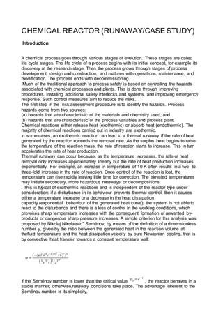
products or dangerous sharp pressure increases. A simple criterion for this analysis was
proposed by Nikolaj Nikolaevicˇ Semënov, by means of the definition of a dimensionless
number y, given by the ratio between the generated heat in the reaction volume at
thefluid temperature and the heat dissipation velocity by pure Newtonian cooling, that is
by convective heat transfer towards a constant temperature wall:
If the Semënov number is lower than the critical value , the reactor behaves in a
stable manner; otherwise,runaway conditions take place. The advantage inherent to the
Semënov number is its simplicity.
2. A runaway exothermic reaction can have a range of results from the boiling over of the
reaction mass, to large increases in temperature and pressure that lead to an explosion.
Such violence can cause blast and missile damage. Release of flammable materials may
result in fire or secondary explosions. Hot liquids and toxic materials may contaminate
the workplace or generate a toxic cloud that may spread off-site.
There can be serious risk of injuries to plant operators, other personnel and the general
public and damage to the local environment. At best, a runaway causes loss and
disruption of production; at worst it has the potential for a major accident, as the incidents
at Seveso and Bhopal have shown.
Hazards can also result from endothermic reaction processes - they can evolve gases,
or can cause rapid crystallization, etc and these may also need controlling.
A number of factors can cause imbalance between the rates of heat production and heat
removal that can result in exothermic runaway or decomposition. Studies of real runaway
incidents show that the main causes are:
(a) mischarging of reactants eg addition of the wrong material or the wrong amount,
addition in the wrong order or at the wrong rate or omission of a reactant;
(b) thermochemistry eg poor appreciation of the heat of reaction, unknown thermal
instability of reactants, intermediates or products;
(c) temperature control eg failure to control temperature, misreading of temperature,
incorrectly positioned or failed thermocouples or coolant failure;
(d) inadequate agitation eg omission to start agitation, agitator failure or incorrect
specification;
(e) maintenance eg unauthorized modifications, build-up of residues, blockages, leaks or
equipment restarted in an incorrect state;
(f) poor control of raw materials eg variable raw material specification or contamination;
and
(g) others eg human errors, not following procedures or poorly defined procedures.
The underlying causes of many incidents involving chemical reactions are:
(a) an inadequate knowledge of the reaction chemistry/thermochemistry;
(b) inadequate engineering design for heat transfer;
(c) inadequate process control; and
(d) inadequate procedures and training
Scale up chemical reactors
One particular factor that has a significant effect on the balance between the heat
generated and the heat lost is the effect of scale-up from laboratory or pilot scale to full
commercial size plant. This is not always appreciated. The heat produced in a reaction
mass increases with its volume, which is proportional to the cube of the reactor diameter.
The heat removed to the surroundings depends on the surface area available for heat
transfer, which is only proportional to the square of the diameter. As reactor scale, and
the ratio of reactor volume to surface area, increases cooling may become inadequate.
Incidents have occurred when processes are carried out on a plant scale that were
uneventful in the laboratory.
Chemical processes usually originate on a small scale in the laboratory and their
development is normally carried out by conducting the reactions on successively larger
scale, through pilot plant stages, before transferring to full size production plant. In the
early stages of process development limited quantities of chemicals are used and full
information about the reaction or side reactions is not usually available. Risk assessment
3. studies and the scale up procedure enable further information to be obtained which is
relevant to the final process plant design.
Failure to scale up properly and to take appropriate precautions may lead to the loss of
process control which in turn may result in a runaway exothermic reaction and /or the
generation or release of toxic materials. The hazards of a runaway reaction and over
pressurization are the two greatest concerns during the scale up process. In the past,
there have been a number of failures to take these issues fully into account
which have led to multiple fatalities, severe damage to property, environmental damage
and business loss.
Other problems that have arisen from inadequate scale up procedures include for
example:
• dust and vapour explosions inside vessels due to the mishandling of reactants and
solvents;
• fires due to overfilling of vessels; • failure to correctly assess electrical equipment for
use in hazardous areas identifying all possible sources of ignition; • auto-ignition of
flammable vapours, usually resulting in a flash fire but sometimes an explosion; and •
inadequate mixing of reactants and solvents.
It is important to remember that most reactions are exothermic. Such reactions move to a
heat balance within the reactor where removal balances production and this balance is at
a temperature above that of the reactor; scale up alters both rates of heat removal and
production. The main factors affecting the removal of heat are the size of the reactor,
stirring and cooling. These factors cannot be over emphasized. The main factors
affecting heat production are concentration of reactants and catalysts, size and starting
temperature. These factors can be subject to change in order to achieve more production
in a shorter time. However, because of the Arrhenius dependence of rate on
temperature, small changes increase heat production more than they
increase heat removal, which hardly changes with increased starting temperature.
Therefore, an attractive production change can move the system from stable balance to
one where stability can never be achieved.
Finally, a maximum stable temperature rise within a system is usually 10 to 20° C, above
that is runaway.
The first and most critical step in the scale up procedure is to undertake a risk
assessment of the proposed chemical process at the concept stage. Where appropriate,
this should include a study of the thermochemistry of the proposed reaction.
The design of a commercial plant can be accomplished by scaling up from laboratory
equipment using pilot plant. In some cases several pilot plants of increasing size may be
used to effect the best design for the larger plant. During the scale up process it is useful
to develop a “basis for safe operation” that spells out the key controls that avoid the
development of unsafe conditions. Risk assessment is an evolving process as scale-up
progresses. At each stage of the scale up procedure the information generated should be
used to review the risk assessment to enable a decision to be made as to whether or not
to proceed to the next stage. If the process is to proceed, the risk assessment should
specify the controls and operating conditions required.
The rate of a chemical reaction is fixed at any given temperature but temperature may be
influenced by mass transfer and heat transfer, which are in turn affected by the size and
design of the reactor. It is not always possible to theoretically assess these effects on a
quantitative basis and in such cases it is usual to carry out trials with water or inert
substances in the intended plant. If this is not feasible purpose built reactor calorimeters
will be required.
Laboratory experiments, carried out in test tubes, small flasks etc., produce a required
chemical or product but do not necessarily indicate side effects of the reaction, i.e. by-
4. products, release of gases or vapours which may be toxic or flammable. Heat releases
may be absorbed by the equipment or surroundings and not noticed. The chemicals used
may be pure materials rather than bulk commercial chemicals, which may contain traces
of impurities. In order to overcome these problems it is essential that the apparatus,
materials and chemicals used at all stages of the scale up accurately reflect those that
will be used in the final plant. In the laboratory reactions are usually carried out in glass
vessels but the scaled up process may well be carried out in containers made of other
materials. With some reactions such changes may be important and could result in
unexpected reactions or problems including catalytic or inhibition effects.
As scale increases the time required to carry out each operation is also likely to increase
and appropriate allowance should be made for this. Pilot plant is used to assist in the
scale up of the chemical process design rather than the mechanical design. It provides
information for economic design, operating parameters, and safety considerations. In
addition, pilot plants can be used in small scale production for evaluation and trial
marketing. Information should be obtained from pilot plant studies to confirm the
decisions made as a result of the risk assessment stage in relation to:
• operating conditions;
• design parameters;
• reactor problems, design, materials of construction;
• unit operations problems;
• materials handling and sampling problems;
• thermal instability and other decomposition;
• phase problems;
• impurities;
• corrosion;
• fouling;
• analytical problems;
• operating procedures;
• working and environment problems; and
• effluent and waste disposal problems.
Laboratory chemicals are often more pure than bulk chemicals. It is important that
reactions are undertaken at an early stage with the bulk chemicals that it are intended to
be used in the final reaction process.
Impurities in bulk chemicals used can cause many problems and these can be identified
in pilot plant studies. Impurities can occur in the feedstock or arise from side reactions,
decompositions, polymerizations, etc. which can cause unexpected effects. Leaks into
the system may bring in unwanted materials such as pump lubricant, seal fluids or heat
transfer media, including water. These may lead to blockages and other problems. Some
impurities can catalyze undesirable explosive reactions or may be thermally
unstable themselves.
Pilot plant studies can reveal corrosion problems. These can be associated with minor
components such as gaskets and diaphragms or with impurities in the reactants. Scaling
up in various size plants can produce variations in reactions, and apparently identical
reactors can give slightly different products with apparently the same feed materials and
operating conditions. This is most marked in fermentation processes.
Pilot plants should be operated by trained and competent personnel. The extra unknown
or unforeseen hazards associated with pilot plant should be compensated for by better
instrumentation and technical control by the operators. If practical, remote handling
systems should be used to minimize the effects of any unforeseen reactions. It must be
remembered, however, that accidents on pilot plant, despite their size, can still have
serious consequences. It is important; therefore, that scale-up of chemical reactions is
5. done correctly so that the eventual reactions can be carried out safely in full size
production plant. 4. Safe operation Information obtained from the risk assessment of the
chemical process and the scale-up studies will enable decisions to be made on the most
appropriate controls to ensure a safe operation.
Safer chemical reactors
The main options that could be considered for a safe operation are:
1. Know the heat of reaction for the intended and other potential chemical
reactions. There are a number of techniques for measuring or estimating heat of
reaction, including various calorimeters, plant heat and energy balances for processes
already in operation, analogy with similar chemistry (confirmed by a chemist who is
familiar with the chemistry), literature resources, supplier contacts, and thermodynamic
estimation techniques. You should identify all potential reactions that could occur in the
reaction mixture and understand the heat of reaction of these reactions.
2. Calculate the maximum adiabatic temperature for the reaction mixture . Use the
measured or estimated heat of reaction, assume no heat removal, and that 100% of the
reactants actually react. Compare this temperature to the boiling point of the reaction
mixture. If the maximum adiabatic reaction temperature exceeds the reaction mixture
boiling point, the reaction is capable of generating pressure in a closed vessel and you
will
have to evaluate safeguards to prevent uncontrolled reaction and consider the need for
emergency pressure relief systems.
3. Determine the stability of all individual components of the reaction mixture at
the maximum adiabatic reaction temperature. This might be done through literature
searching, supplier contacts, or experimentation. Note that this does not ensure the
stability of the reaction mixture because it does not account for any reaction among
components, or decomposition promoted by combinations of components. It will tell you if
any of the individual components of the reaction mixture can decompose at temperatures
which are theoretically attainable. If any components can decompose at the maximum
adiabatic reaction temperature, you will have to understand the nature of this
decomposition and evaluate the need for safeguards including emergency pressure relief
systems.
4. Understand the stability of the reaction mixture at the maximum adiabatic
reaction temperature. Are there any chemical reactions, other than the intended
reaction, which can occur at the maximum adiabatic reaction temperature? Consider
possible decomposition reactions, particularly those which generate gaseous products.
These are a particular concern because a small mass of reacting condensed liquid can
generate a very large volume of gas from the reaction products, resulting in rapid
pressure generation in a closed vessel. Again, if this is possible, you will have to
understand how these reactions will impact the need for safeguards, including
emergency pressure relief systems. understanding the stability of a mixture of
components may require laboratory testing.
5. Determine the heat addition and heat removal capabilities of the pilot plant or
production reactor. Don’t forget to consider the reactor agitator as a source of energy –
about 2550 Btu/hour/horsepower. Understand the impact of variation in conditions on
heat transfer capability. Consider factors such as reactor fill level, agitation, fouling of
internal and external heat transfer surfaces, variation in the temperature of heating and
cooling media, variation in flow rate of heating and cooling fluids.
6. Identify potential reaction contaminants. In particular, consider possible
contaminants which are ubiquitous in a plant environment, such as air, water, rust, oil
6. and grease. Think about possible catalytic effects of trace metal ions such as sodium,
calcium, and others commonly present in process water. These may also be left behind
from cleaning operations such as cleaning equipment with aqueous sodium hydroxide.
Determine if these materials will catalyze any decomposition or other reactions, either at
normal conditions or at the maximum adiabatic reaction temperature.
7. Consider the impact of possible deviations from intended reactant charges and
operating conditions. For example, is a double charge of one of the reactants a
possible deviation, and, if so, what is the impact? This kind of deviation might affect the
chemistry which occurs in the reactor – for example, the excess material charged may
react with the product of the intended reaction or with a reaction solvent. The resulting
unanticipated chemical reactions could be energetic, generate gases, or produce
unstable products.
Consider the impact of loss of cooling, agitation, and temperature control, insufficient
solvent or fluidizing media, and reverse flow into feed piping or storage tanks.
8. Identify all heat sources connected to the reaction vessel and determine their
maximum temperature. Assume all control systems on the reactor heating systems fail
to the maximum temperature. If this temperature is higher than the maximum adiabatic
reaction temperature, review the stability and reactivity information with respect to the
maximum temperature to which the reactor contents could be heated by the vessel heat
sources.
9. Determine the minimum temperature to which the reactor cooling sources could
cool the reaction mixture. Consider potential hazards resulting from too much cooling,
such as freezing of reaction mixture components, fouling of heat transfer surfaces,
increase in reaction mixture viscosity reducing mixing and heat transfer, precipitation of
dissolved solids from the reaction mixture, and a reduced rate of reaction resulting in a
hazardous accumulation of unreacted material.
10. Consider the impact of higher temperature gradients in plant scale equipment
compared to a laboratory or pilot plant reactor. Agitation is almost certain to be less
effective in a plant reactor, and the temperature of the reaction mixture near heat transfer
surfaces may be higher (for systems being heated) or lower (for systems being cooled)
than the bulk mixture temperature. For exothermic reactions, the temperature may also
be higher near the point of introduction of reactants because of poor mixing and localized
reaction at the point of reactant contact. The location of the reactor temperature senso r
relative to the agitator, and to heating and cooling surfaces may impact its ability to
provide good information about the actual average reactor temperature. These problems
will be more severe for very viscous systems, or if the reaction mixture includes solids
which can foul temperature measurement devices or heat transfer surfaces. Either a local
high temperature or a local low temperature could cause a problem. A high temperature,
for example, near a heating surface, could result in a different chemical reaction or
decomposition at the higher temperature. A low temperature near a cooling coil could
result in slower reaction and a buildup of unreacted material, increasing the potential
chemical energy of reaction available in the reactor. If this material is subsequently
reacted because of an increase in temperature or other change in reactor conditions,
there is a possibility of an uncontrolled reaction due to the unexpectedly high quantity of
unreacted material available
11. Understand the rate of all chemical reactions. It is not necessary to develop
complete kinetic models with rate constants and other details, but you should understand
how fast reactants are consumed and generally how the rate of reaction increases with
temperature. Thermal hazard calorimetry testing can provide useful kinetic data.
12. Consider possible vapor phase reactions. These might include combustion
reactions, other vapor phase reactions such as the reaction of organic vapors with a
7. chlorine atmosphere, and vapor phase decomposition of materials such as ethylene
oxide or organic peroxide.
13. Understand the hazards of the products of both intended and unintended
reactions.
For example, does the intended reaction, or a possible unintended reaction, form viscous
materials, solids, gases, corrosive products, highly toxic products, or materials which wills
well or degrade gaskets, pipe linings, or other polymer components of a system? If you
find an unexpected material in reaction equipment, determine what it is and what impact
it might have on system hazards. For example, in an oxidation reactor, solids were known
to be present, but nobody knew what they were. It turned out that the solids were
pyrophoric, and they caused a fire in the reactor.
14. Consider doing a Chemical Interaction Matrix and/or a Chemistry Hazard
Analysis.
These techniques can be applied at any stage in the process life cycle, from early
research through an operating plant6. They are intended to provide a systematic method
to identify chemical interaction hazards and hazards resulting from deviations from
intended operating conditions.
15. Rapid reactions are desirable. In general, you want chemical reactions to occur
immediately when the reactants come into contact. The reactants are immediately
consumed and the reaction energy quickly released, allowing you to control the reaction
by controlling the contact of the reactants. However, you must be certain that the reactor
is capable of removing all of the heat and any gaseous products generated by the
reaction.
16. Avoid batch processes in which all of the potential chemical energy is present
in the system at the start of the reaction step. If you operate this type of process,
know the heat of reaction and be confident that the maximum adiabatic temperature and
pressure are within the design capabilities of the reactor.
17. Use gradual addition or “semi-batch” processes for exothermic reactions. The
inherently safer way to operate exothermic reaction process is to determine a
temperature at which the reaction occurs very rapidly. Operate the reaction at this
temperature, and feed at least one of the reactants gradually to limit the potential energy
contained in the reactor. This type of gradual addition process is often called “semi-
batch.” A physical limit to the possible rate of addition of the limiting reactant is desirable
– a metering pump, flow limited by using a small feed line, or a restriction orifice, for
example. Ideally, the limiting reactant should react immediately, or very quickly, when it is
charged. The reactant feed can be stopped if necessary if there is any kind of a failure
(for example, loss of cooling, power failure, loss of agitation) and the reactor will contain
little or no potential chemical energy from unreacted material. Some way to confirm
actual reaction of the limiting reagent is also desirable. A direct measurement is best, but
indirect methods such as monitoring of the demand for cooling from an exothermic batch
reactor can also be effective.
18. Avoid using control of reaction mixture temperature as the only means for
limiting the reaction rate. If the reaction produces a large amount of heat, this control
philosophy s unstable – an increase in temperature will result in faster reaction and even
more heat being released, causing a further increase in temperature and more rapid heat
release. If there is a large amount of potential chemical energy from reactive materials, a
runaway reaction results. This type of process is vulnerable to mechanical failure or
operating error .A false indication of reactor temperature can lead to a higher than
expected reaction temperature and possible runaway because all of the potential
chemical energy of reaction is available in the reactor. Many other single failures could
lead to a similar consequence ,a leaking valve on the heating system, operator error in
8. controlling reactor temperature ,failure of software or hardware in a computer control
system.
19. Account for the impact of vessel size on heat generation and heat removal
capabilities of a reactor. Remember that the heat generated by a reactive system will
increase more rapidly than the capability of the system to remove heat when the process
is operated in a larger vessel. Heat generation increases with the volume of the system –
by the cube of the linear dimension. Heat removal capability increases with the surface
area
of the system, because heat is generally only removed through an external surface of the
reactor. Heat removal capability increases with the square of the linear dimension. A
large reactor is effectively adiabatic (zero heat removal) over the short time scale (a few
minutes) in which a runaway reaction can occur. Heat removal in a small laboratory
reactor is very efficient, even heat leakage to the surroundings can be significant. If the
reaction temperature is easily controlled in the laboratory, this does not mean that the
temperature can be controlled in a plant scale reactor. You need to obtain the heat of
reaction data discussed previously to confirm that the plant reactor is capable of
maintaining the desired temperature.
20 Use multiple temperature sensors, in different locations in the reactor for rapid
exothermic reactions . This is particularly important if the reaction mixture contains solids,
is very viscous, or if the reactor has coils or other internal elements which might inhibit
good mixing.
21 Avoid feeding a material to a reactor at a higher temperature than the boiling
pointof the reactor contents. This can cause rapid boiling of the reactor contents and
vapor generation.
CASE STUDY
The process considered is the polymerization of vinyl chloride monomer in the PVC. The
case study is based on a well known process which treats a substance the VCM that is
flammable and produces toxic combustion products . The process is based a semi
continuous plant consisting of several reactors with times of 10 hours of polymerization.
The heart of the process is a cstr mechanically stirred reactor where the reaction heat is
removed by cooling water in shirt and where the reaction takes place in multiple reactors
in parallel so that it operates in a semi continuous mode. If the reactor has undergone
maintenance actions after the last batch, this should be reclaimed from the air to
minimize oxidation of the monomer which produces HCl ,which can lead to corrosion of
the reactor. In other way the first step is to treat the reactor with an antifouling solution to
prevent polymerization on the walls.
Then the liquid VCM is loaded to the reactor. An initiator (liquid peroxide) is dissolved in
the monomer. Because this compound can decompose it is stored at low temperature in
special bunkers. Small amounts are taken for common use. The peroxide is introduced
into a small receiver to make sure that only the correct quantity is used.
After the initiator is added, the reactor is heated with hot water and brought to reaction
temperature. The agitation is necessary to suspend the monomer in the water used to
control the heat of reaction and for the purposes of product quality. Since the reaction is
exothermic cooling water is circulating in the reactor jacket. The reaction is said finished
when the pressure decreases, indicating that most of the monomer has reacted. The
9. polymer is discharged and sent downstream of the reactor for further treatment
(monomer recovery, stripping, drying).
The first step in developing the process is to identify the process parameters, define the
risks to the safety and the environmental impact and seek solutions for a safer process
.For this information are needed about the hazardous properties of the substances
involved and products. However the reaction conditions and the initiator must be carefully
chosen to ensure that the reaction rate is adequately monitored and avoiding phenomena
of runaway while ensuring the quality and improved production capacity .The choice is
the polymerization in water but this requires the use of small quantities of hazardous
initiators whose security must be assessed.
In this case the main hazards are associated with flammability and toxicity of the
combustion products VCM..As first step it is useful to examine the incidents over the
years:
in 1961 in a PVC plant in Japan an accident that killed 4 people was due to the discharge
of the batch from the wrong reactor so that the unreacted monomer was released in the
plant which contained reactors in parallel. The VCM vapors were triggered by a spark of
some machinery resulting in an explosion. In another incident a worker accidentally
opened a man-hole of a reactor in service with leakage of large amounts of monomer
that is burned and led to the death of maintenance man. In another incident an operator
loaded the monomer reactor with the bottom valve open. Other incidents occurred during
the maintenance of a VCM pump due to the presence of the peroxide contamination, or
there was a release of VCM from a scrubber due to maintenance problems to a clogged
valve resulting in ignition and death of operators.
Thereby the risk can be summarized as:
Jetfire: a leak from a pressurized system which burns and forms a jet of fire that impinge
other equipment (a jet from a 2 "hole produces approximately 10 meters) jet-fire
Flash -fire: a release of a liquid in pressure produces flammable vapors traveling toward
an ignition source.
Pool fire: a liquid release form a pool burning with flames which can be two high, three
times the width of the pool
Bleve: a pressurized container full of monomer exposed to external fire can yield due to
metallurgical weakness, such an event leads to the formation of a ball of fire. The safety
valves do not prevent the Bleve.
Esplosion: the loss of gas in the confined environment brings in the presence of ignition
to explosion source.
Hydraulic Failure: Over filling a container with subsequent expansion of the liquid due to
heating can lead to the collapse of the vessel.
Stress corrosion failure: air in the system can lead to the presence of HCl that can lead
to a loss of mechanical integrity.
Toxic Combustion products: the combustion of the monomer leads to the presence of
phosgene, HCl, CO along with other toxic substances.
Runaway polimerization: polymerization if not well controlled can lead to excess
pressure and rupture the reactor
10. DEFINITION OF THE PROCESS
The operation steps are summarized as follows:
Pre-evacuation of air: if the reactor has been in maintenance ,oxygen from the air must
be removed for the product quality problems and for the mechanical integrity of the
reactor (Corrosion)
Preparation of the reactor: the empty rector is washed with water, tested for leaks, if the
manhole was opened and treated with antifouling.
demineralized water load: a controlled load of water is placed in reactor. An excess can
lead to overload, a fault can lead to quality problems and problems of runaway. All other
additives are added.
Charging the monomer: an accurate loading of the monomer is made.
Heating of the reactor: the initiator is added from its receiver, the reactor is heated to
the temperature at which begins the reaction (5 C below the operating temperature)
Reaction: the heating is removed, cooling water in the jacket is passed through .The
temperature of polymerization is checked.
Termination: When the pressure in the reactor is lowered means that there is no more
monomer to react, and the batch is downloaded
Discharge reactor: the reactor is discharged to the downstream unit, to prevent polymer
deposit on the bottom ,the stirrer is held running. The monomer is recovered for its reuse
in the reaction.
There are two other systems that are used in emergency phase:
Shortstop chemical: an agent that terminates the polymerization of batch. However the
agitation is required for a good distribution of the shortstop to quickly stop the
polimerization. In case of failure of the agitator the shortstop must be added in 2 minutes,
to use still the shaking motions of liquid in reaction. As back-up it is used to lower the
pressure in the reactor to generate the bubbles that keep the reactor under stirring.
Automatic depressurization: in case of uncontrolled reaction, the system can be kept
under control with a depressurization of the reactor and discharge of vapors The heat of
vaporization removes the heat of reaction.
The following prevention strategy can be used:
A) to treat the runaway scenarios where the agitator is running ,It can be proposed the
following sequence:
• High temperature or pressure the maximum flow rate of cooling water is activated
(Interlock) and alerts the operator with alarm
• If the temperature and pressure continue to grow the operator activates the addition of
shortstop
• If even this method stops the reaction a "high-high" alarm on the temperature and
pressure and the interlock system depressurize the reactor
11. B) for runaway occurring stirrer for not running , other protections in addition to those of
the case A they are:
• The loss of agitation is indicated for low amperage to the operator by an alarm and after
the addition of a shortstop , a depressurization is required to mix the shortstop to the
mass. (Depressurization of the system is back-up to the runaway control)
C) Low or no-presence of cooling water: the same security of the case A, in addition if
the low flow rate is caused by the loss of electrical power, the operator is alerted by the
low flow and acts by entering the turbine steam on the pump.
D) water Overload or monomer: can lead to over-filling of the reactor with hydraulic
damage. This damage is avoided if there is an interlock between the weight of the reactor
cells( with high weight alarm) and the heating system of the reactor. A back-up is
provided with an interlock "high-high" level of pressure that activates the emergency
depressurizing valves.
E) stirrer seal break: this can cause dangerous spills of monomer. This is secured with
interlock high agitator sealing pressure and depressurization emergency.
F) As the shortstop is so important to control a runaway. An interlock is inserted to ensure
the availability of the shortstop, the interlock does not allow the loading of monomer if the
shortstop level in its container is low and if there is no nitrogen pressurization.
ANALYSIS INCIDENTAL EVENTS
Event 1: Lack of cooling water
This event starts a runaway which can become catastrofic The protection is the
shortstop and the safety valves.
Event 2: agitator out of service
The event starts a runaway similar event 1 except that the depressurization is required to
mix the shortstop in the mass of the reactor, with lack of agitation ,the maximum flow rate
of cooling is insufficient to stop the runaway so the interlock of depressurization is the
only effective.
Event 3: Lack Electricity: same consideration as Event 2
Event 4: cooling pump out of service
This event is similar to the event 1 except that the operator can stop the runaway only by
operating the turbine on the relevant pump or by adding the shortstop.
Event 5: double charge initiator
This event leads to an energetic runaway with high rate of reaction and evolution of heat
12. even if the cooling is running .Both the PSV and the interlock depressurization system
are indicated for this event, as well as the addition of shortstop.
Event 6: Over-filling of the reactor
This event can lead to dangerous leakage of monomer. With the high number of batches
per year this event is very likely .The interlock and High weight alarm, level on weight
cells are deemed sufficient. The interlock of depressurization is effective.
Event 7: Over-heating of the reactor
This event leads to runaway similar event 1.Effective prevention systems are interlocking
with the emergency cooling water and depressurization.
Event 8: sealing the reactor out of service
The special design of the seal reduces leakage of the monomer. The additional
ventilation is sufficient to minimize the risk and the low presence of operators on the plant
reduces the risk.
DESIGN OF A CONTROL SYSTEM
An electronic control system (PID control, PLC, DCS) is selected for the following
reasons:
• The plant consists of several reactors
• The control room is at a remote location
• The valves have on off switches with the position indicated
• Operations from the control room reduce the presence of operators on the system
• Electronic Input are useful for recipe management
• It is possible to make a data analysis compared with those of the field
operating station
The operators in the control room have access to a lot of equipment through the console
to make an analysis of the process, to make problem solving analysis, the variable status
monitoring, trend analysis, alarm analysis
sensor selection:
Level in the reactors: choosing a radar level that can be mounted outside the reactor.
The system is mounted to monitor the loading and unloading stages of reactor. An
internal level would be less desirable because it would operate in a stirred mass and
subject to the systems of washing with high pressure water. Delete an entry into the
reactor is important to the carcinogenic nature of the monomer.
Temperature: The temperature is measured from the RDT devise inside sheaths in order
to facilitate the slipping of the thermocouple. The cockpit is equipped with a pressure
indicator to indicate any losses in the cockpit.
Pressure: The primary system consists of a pressure transmitter with sealing diaphragm.
13. Capacity: to load the monomer using turbine flowmeters that have appropriate
characteristics of reliability and also allow integration of the past volume.
Weight: load cells are supplied to each reactor to provide an indirect indication of the
level and indication of the amount loaded.
stirrer current: a current sensor is provided for indication of stirrer running
final elements selection
The valves are selected according to their characteristics for minimal losses in the
environment and in the second place to minimize polymer buildup. Ball valves or butterfly
are selected.
Controller Selection
a DCS is used , because transients are relatively low and a normal DCS is sufficient for
the application.
administrative procedures to maintain integrity
It may be necessary to conduct a FAT (factory acceptance test) on the DCS. A control
system to validate the procedure of the system control logic is required including the
analysis of the control sequence of the reaction to batch ..SOP (standard operating
procedures) will be provided to operators which describes all process steps, how the
process control (set-point, process alarms, temperature and pressure limits, range during
the reaction, which actions to take in case of deviation)
An operator confirms that the action was taken should be required before moving on to a
next emergency step. Procedure step that describes what to do when critical parameters
are in alarm. Another procedure must be issued so that if the software up-to date safety
is not compromised.
Interlock procedures
A procedure must state that no interlock can be bypassed during the time required for the
reaction. No alarm should be bypassed at any time of the process. Any calibration of
equipment must be done with the process not operating The procedure must provide that
if there are abnormalities in the interlock the operator must proceed with the plant
shutdown. The procedure should not allow any changes to the process parameters and
interlocks when the first has not been sufficiently endorsed and except there was
conducted a HAZOP analysis or FMEA.
The procedure must allow access to interlocks systems by authorized persons only who
knows the password system and its operation. All maintenance work on the control and
interlock systems should be documented, indicating the initial problem, identify the
causes, and the implementation of the solution, provided the person responsible .The
14. procedure must provide that a workstation is configured for your system control and
another for interlocks. A functional test should be conducted on the interlocks before
putting them into service and at regular intervals. The test system must validate the
following points:
• The operation and range of inputs including the primary devices and the input modules
of interlocks
• The logic of the operations associated with each input device
• The set points of all inputs and the contact position of the switch
Alarms with their duties
• The function of all output or final control elements
• The correct action of the final control elements (valves, actuators)
• Any variable or output that indicates the status of the installation process
• The current software version
• If the action in the absence of the energy system (EE, instrument air) is correct
other procedures
The training of staff to use the software must be conducted before putting the system in
march and should be repeated in case of changes.
The documentation on the current software system must be updated, any changes must
be documented.
An audit should be done on the control and follow-up must be done The audit must
include:
• Review of all changes made since the last audit or verification
• Review of all the problems that occurred with the software
• Verification of the functional checks of the system annually facts
• Check that all official documentation is in order
• Verify that the person know how to use the software correctly
• Check that the planned has been realized
• Check emergency procedures including simulation periods
references:
1) guidelines for safe automation of chemical processes -CCPS-Aiche
15. 2)HSE: Design and Operating safe chemical reaction processes
3)Treccani: Chemical Reactors
4)CCPS: A Checklist for Inherently Safer Chemical Reaction Process Design and
Operation
5)HSE : Chemical reaction hazards and the risk of thermal runaway
6)Society of chemistry :Inherent safer chemical processes
7) Integrated Pollution Prevention and Control Reference Document on Best Available
Techniques for (the Manufacture of Organic Fine Chemicals)
8) Society of chemistry :SAFETY ISSUES IN THE SCALE-UP OFCHEMICAL
REACTIONS
9) Catalysis Today :Scale up of Chemical Reactors
10)ANPA: Sicurezza Reattori Chimici
11)ICHEME: THE CONTROL OF RUNAWAY POLYMERISATION REACTIONS BY
INHIBITION TECHNIQUES
12) ICHEME :AN EXPLOSION ACCIDENT – CAUSES AND SAFETY INFORMATION
MANAGEMENT LESSONS TO BE LEARNED
13) ICHEME : RUNAWAY REACTION DURING PRODUCTION OF AN AZO DYE
INTERMEDIATE