SlideShare ist ein Scribd-Unternehmen logo
1 von 6
Downloaden Sie, um offline zu lesen
IJSRD - International Journal for Scientific Research & Development| Vol. 3, Issue 10, 2015 | ISSN (online): 2321-0613
All rights reserved by www.ijsrd.com 815
A Survey on Single Phase to Three Phase Cyclo-Converter Fed Induction
Motor
Anshu Sharma1
Shilpi Sisodiya2
2
Professor
1,2
Department of Electrical Engineering
1,2
Maharana Pratap College of Technology Gwalior, India
Abstract— In various application of electrical energy
especially in in industrial areas there are two type of current,
Direct Current and Alternating Current are used. Generally
fixed voltage, constant frequency Single-Phase or Three-
Phase AC is easily available, yet for different applications
various types of magnitudes and/or frequencies are essential.
This paper presents a survey on 1-ϕ to 3-ϕ cycloconverter
technique using thyristor with 3-ϕ induction motor along
load frequency analysis. The cycloconverter is inspected in
its utmost straight forward form without further output
filters or elaborate control technique.
Key words: Cycloconverter, Thyristor, Single-Phase to
Three-Phase conversion, Frequency
I. INTRODUCTION
Power electronics devices have wide applications in
electrical power system. Noteworthy improvements have
taken place in control, analysis, modeling and practical
implementation aspects of cycloconverter and their
applications to the flexible-speed ac drives. This paper is the
survey of applications of cycloconverter fed induction
motors to electrical energy system. Frequency changers are
an extending field of power conversion innovation. The
increasing usage of ac motors in the production of electrical
power from variable speed sources are illustrations of this
area application. Currently systems of frequency changers
incorporated rotating machines. These systems have been to
a great extent supplanted by static frequency changers
utilizing power semiconductor devices. VSI (voltage source
inverter) fed drives are most widely used in low and
medium power applications, but not used widely in high
power applications. CSI (current source inverter) fed drives
are widely used for medium voltages high power
application.
Another power electronic device called
cycloconverter is utilized as a part of high power application
for driving induction motor and synchronous motors. They
are usually phase-controlled and traditionally utilize
thyristors because of their simplicity of phase commutation.
. The fundamental guideline of this converter, conceived and
patented by ~hazeltine in 1926, is to construct an alternating
voltage wave of lower frequency from successive voltage
waves of a higher frequency multiphase ac supply by a
switching arrangement.
II. CYCLOCONVERTER
Usually, the AC-AC converters with semiconductor
switches are normally classified into indirect converter
which uses a DC link between the two AC systems and
direct converter that offers direct conversion. Indirect
converter contains of two converter stages and energy
storing element, which change input AC to DC and then
reconverting DC back to output ac with variable amplitude
and frequency as presented in Fig1(a). In direct converter
there is no need of DC link as shown in Fig 1(b) etc.
Fig. 1: AC/AC Converter (a) Indirect Converter (b) Direct
Converter
Cycloconverters are the direct type converters utilized as
a part of high power applications driving induction
and synchronous engines. They are normally phase-
controlled and they generally utilize thyristors because of
their simplicity of phase compensation. The fundamental
block diagram of Cycloconverter is given in Fig 2.
Fig. 2: Block diagram of Cycloconverter
A Cycloconverter is sort of power controller in
which an exchanging voltage at supply frequency is changed
specifically to an alternating voltage at load frequency with
no intermediate DC stage. In a line commutated
Cycloconverter, the supply frequency is more noteworthy
than the load frequency. The working standards were
created in the 1930s while the grid controlled mercury arc
rectifier got to be accessible. The procedures were applied in
Germany, where the three stage 50 Hz supply was changed
over to a single phase AC supply at 16⅔ Hz for railroad
traction. In the United States, a 400 HP plan in which a
synchronous motor was supplied from a Cycloconverter
including 18 thyratrons was in along working for various
years as a power station assistant drive. Then again, in light
of the fact that these early plans were not adequately
appealing technically or financially, they were discontinued.
Through the timings of its firing pulses, a Cycloconverter is
controlled, so it delivers a substituting (alternating) output
voltage. By monitoring the frequency and depth of phase
modulation of the terminating points of the converters, it is
conceivable to control the frequency and amplitude of the
output voltage. In this manner, a Cycloconverter has the
capability for constant also autonomous control over both its
output frequency and voltage. This frequency is regularly
A Survey on Single Phase to Three Phase Cyclo-Converter Fed Induction Motor
(IJSRD/Vol. 3/Issue 10/2015/178)
All rights reserved by www.ijsrd.com 816
under 1/3 of the given frequency. The nature of the output
voltage wave and its symphonious distortion additionally
force the restriction on this frequency. The distortion is low
at low output frequencies. The Cycloconverters are typically
used to give either a variable frequency from a constant
input frequency or a constant frequency from a variable
input frequency. A Cycloconverter can carry load of any
power factor and permits power flow in both the directions.
The output voltage wave shape definitely consist
symphonious distortion parts additionally to the required
sinusoidal component. These distortion terms are delivered
as an important result of the fundamental mechanism of the
Cycloconverter, whereby the output voltage is created from
portions of the given voltage waves. These twists can be
minimized by sufficient channels at the yield. Increments
happen in the distortion of the output voltage if the
proportion of the output and input frequency increments [1].
A. Applications Of Cycloconverter Are:
- used for controlling the speed of high power AC drives
- used in high frequency induction motors
- used in static VAR generators
- they are used as a power supplier in the aircrafts and
space vehicles
- used in High voltage DC(HVDC) transmission for
interconnecting two power grids operating at two
different frequencies.
III. ADVANTAGES OF CYCLOCONVERTER
1) Conversion of frequency, directly without any
intermediate stage.
2) Natural commutation – Compact system.
3) Transfer of Power in either direction.
4) Capable of reproduction over the complete speed
range, down to standstill.
5) Commutation failure leads only to blown-off of
individual fuses only.
6) Provides a high quality sinusoidal waveform at low
output frequencies since it is created from a huge
number of parts of the supply waveform. This is
frequently preferable for very low speed applications.
IV. OPERATING PRINCIPLE OF CYCLOCONVERTER
A. Single-Phase To Single-Phase (1ϕ-1ϕ) Cycloconverter:
This converter comprises of consecutive association of two
full-wave rectifier circuits. Fig 3 demonstrates the working
waveforms for this converter with resistive load.
The input voltage vs, is an ace voltage at a
frequency, Vi as showed in Fig. 3a. All the thyristors are
fired up at a=0° firing angle, i.e. thyristors acts like diodes.
Firing angle for positive converter is meant by αp and for
negative converter αn. The frequency of Vo can be altered
by shifting the number of cycles, positive and negative
converters work.
Consider the working of the cycloconverter to
accomplish ¼ of the input frequency at the output. For the
beginning two cycles of vs, the positive converter acts to
giving current to the load. It rectifies the input voltage;
thusly, the load found four positive half cycles as found in
Fig. 3b. In the subsequent two cycles, the negative converter
works giving current to the load in the opposite direction.
The current waveforms are not shown in the figures due to
the certainty that the resistive load current will have the
similar waveform as the voltage though simply scaled by the
resistance. Note that when one of the converters works the
other one is impaired, so that there is no present circling
between the two rectifiers.
Fig. 3: (a) Cycloconverter, Single-phase to single-phase(1ϕ-
1ϕ)
Fig. 3: shows cycloconverter waveforms of Single-phase to
single-phase
1) Input voltage
2) Output voltage for zero firing angle
3) Output voltage with firing angle p/3 rad
4) Output voltage with varying firing angle
Due to the frequency of the output, Vo in fig.3b is
one fourth of the input voltage, i.e. fo/fi=1/4 that’s why it is
step down cycloconverter. Instead of it, if the cycloconverter
frequency has correlation like this fo/fi>1, it’s known as
step-up cycloconverters. Notify that step-down
cycloconverters are further commonly used in compare step-
up ones.
The frequency of vo can be adjust by altering the
figure of cycles the positive and the negative converters
works. It can only change as integer multiples of fi in 1ϕ-
1ϕcycloconverters.With the above operation, the 1ϕ-
1ϕcycloconverter can only supply a certain voltage at a
certain firing angle a. The dc output of each rectifier is:
(1)
where V is the input r.m.s voltage.
The dc value per half cycle is shown as dotted in
Fig. 3d. Then the peak of the fundamental output voltage is
( ) (2)
A Survey on Single Phase to Three Phase Cyclo-Converter Fed Induction Motor
(IJSRD/Vol. 3/Issue 10/2015/178)
All rights reserved by www.ijsrd.com 817
Equation 2 infers that the basic output voltage
relates to a. Hence changing a, the fundamental output
voltage can be controlled.
Fixed operation gives a rough output waveform
with rich harmonic content. The dotted lines in Fig. 3b and c
demonstrate a square wave. If the square wave can be
adjusted to look more like a sine wave, the harmonics would
be reduced. Hence is modulated as shown in Fig. 3d.
Presently, the six-stepped dotted line is more like a sine
wave with fewer harmonics. The more pulses there are with
different a's, the less are the harmonics.
B. Three-Phase to Single-Phase (3ϕ-1ϕ) Cycloconverter:
There are two types of three-phase to single-phase (3ϕ-1ϕ)
cycloconverters: 3ϕ-1ϕ half-wave cycloconverter (Fig. 4)
and 3ϕ-1ϕ bridge cycloconverter (Fig. 5). Like the 1ϕ-1ϕ
converter case, the 3ϕ-1ϕcycloconverter applies rectified
voltage to the load. Both of them, positive and negative
converters can generate voltages at either polarity, however
positive converter can only supply positive current and the
negative converter can only supply negative current
Accordingly, the cycloconverter can operate in four
quadrants: (+v, +i) and (-v, -i) rectification modes and (+v, -
i) and (-v, +i) inversion modes. The modulation of the
output voltage and the basic output voltage are shown in
Fig. 6. It seems that α is sinusoidally modulated over the
cycle to generate a harmonically idyllic output voltage.
Fig. 4: 3f-1f Half-Wave Cycloconverter
Fig. 5: 3ϕ-1ϕ Bridge Cycloconverter
Fig. 6: 3ϕ-1ϕ Half-Wave Cycloconverter Waveforms A) +
Converter Output Voltage B) Cosine Timing Waves C) –
Converter Output Voltage
The extremity of the current defines whether the
positive or negative converter should be supplying power to
the load. Customarily, the firing angle for the positive
converter is named aP, and that of the negative converter is
named a N. At the point when the polarity of the current
changes, the converter beforehand providing the current is
disabled and the other one is enabled. The load continuously
needs the essential voltage to be continuous. Subsequently,
during the current polarity reversal, the average voltage
provided by both of the converters ought to be equal. Else,
switching from one converter to the next one would cause
an undesirable voltage jump. To avoid this problem, the
converters are forced to generate the same average voltage
at all times. Accordingly, the accompanying condition for
the firing angles ought to be met
……. (1)
The fundamental output voltage in Fig. 6 can be given as:
( ) ……. (2)
Where Vo is the rms value of the fundamental voltage
At a time to the output fundamental voltage is
( ) ……. (3)
The positive converter can supply this voltage if aP satisfies
the following condition.
Where (p=3 for half wave converter and 6 for bridge
converter)
From the a condition (3)
The firing angles at any instant can be found from
eq. The operation of the 3ϕ-1ϕ bridge cycloconverter is
similar to the above 3ϕ-1ϕ half-wave cycloconverter. Note
that the pulse number for this case is 6.
C. Three-Phase to Three-Phase (3ϕ-3ϕ) Cycloconverter:
In the occurrence that the outputs of 3-ϕ to 1-ϕ converters
of the same type are associated in wye or delta and if the
output voltages are 2π/3 radians phase moved from each
other, the subsequent converter is a three phase to three-
phase (3ϕ-3ϕ) cycloconverter. The subsequent
cycloconverter are appeared in Figs. 7 and 8 with wye
connections. If the three converters associated are half-wave
converters, then it’s known as a 3ϕ-3ϕ half-wave
cycloconverter. If instead, bridge converters are utilized,
A Survey on Single Phase to Three Phase Cyclo-Converter Fed Induction Motor
(IJSRD/Vol. 3/Issue 10/2015/178)
All rights reserved by www.ijsrd.com 818
then the result is a 3ϕ-3ϕ bridge cycloconverter. 3ϕ-3ϕ half-
wave cycloconverter is also known as 3-pulse
cycloconverter or an 18-thyristor cycloconverter. Then
again, the 3ϕ-3ϕ bridge cycloconverter is likewise called a
6-pulse cycloconverter or a 36-thyristor cycloconverter. The
operation of each phase is clarified in the previous segment.
Fig. 7: 3ϕ-3ϕ Half-Wave Cycloconverter
Fig. 8: 3ϕ-3ϕ Bridge Cycloconverter
The three-phase cycloconverter are in a general
sense utilized in ac machine drive systems running three
phase synchronous and induction machines. They are more
beneficial when utilized with a synchronous machine due to
their output power factor features. A cycloconverter can
provides lagging, leading, or unity power factor loads while
its input is frequently lagging. A synchronous machine can
figure out any power factor current from the converter. This
typical operation matches the cycloconverter to the
synchronous machine. Then again induction machines can
only figure out lagging current, so the cycloconverter does
not have an edge paralleled with alternate converters in this
facet for running an induction machine. Then again,
cycloconverter are utilized as a part of Scherbius drives for
speed control purposes driving wound rotor induction
motors.
D. Single-Phase to Three-Phase (1ϕ-3ϕ) Cycloconverters:
In recent times, with the drop in the size and the cost of
power electronics switches, single-phase to three-phase
cycloconverters (1ϕ-3ϕ) initiating more research attention.
Generally, an H -bridge inverter generates a high frequency
single-phase voltage waveform, which is fed to the
cycloconverter either through a high frequency transformer
or not. If a transformer is used, it isolates the inverter from
the cycloconverter. In further, additional taps from the
transformer can be utilize to power other converters
generating a high frequency ac connection. The single-phase
high frequency ac (hfac) voltage can be either sinusoidal or
trapezoidal. There may be zero voltage intervals for control
purposes or zero voltage commutation. Fig. 9 demonstrates
the circuit diagram of aordinaryhfac link converter. These
converters are not commercially available yet. They are in
the research state
Fig. 9: High Frequency Ac Link Converter (1f Hf Inverter +
(1f-3f) Cycloconverter)
Cycloconverter produce harmonic rich output
voltages. When cycloconverter are used to run an ac
machine, the leakage inductance of the machine filters the
greater part of the higher frequency harmonics and reduces
the magnitudes of the lower order harmonics labels.
V. LITERATURE REVIEW
Xiaofeng Yang [3] presented an advance single-phase to
three-phase cycloconverter appropriate for driving an
induction motor. By means of discrete variable frequency
system, a single-phase to three-phase modulation technique
is proposed the output frequency of this cycloconverter may
be up to half of the input frequency. Only six commonly
communicated thyristors are employed, so the subsequent
cycloconverter-motor drive framework is cheap and
compact. Programming in C and assembly language has
been written for real-time control. The reproduction in view
of Matlab /Simulink is used to foresee the presentation for
the cycloconverter and induction motor toolbar
Ashwini Kadam [4] paper present is to control the
speed of an induction motor by changing the frequency with
three level diode clamped multilevel inverter. To get high
quality sinusoidal output voltage with reduced harmonics
distortion, multicarrier PWM control plan is presented for
diode clamped multilevel inverter .This technique is
executed through changing the supply voltage and frequency
A Survey on Single Phase to Three Phase Cyclo-Converter Fed Induction Motor
(IJSRD/Vol. 3/Issue 10/2015/178)
All rights reserved by www.ijsrd.com 819
applied to the three phase induction motor at constant ratio.
The proposed system is an actual replacement for the
conventional strategy which delivers high switching losses,
result in poor drive performance. The simulation &
implementation results reveal that the proposed circuit
efficiently controls the motor speed and increases the drive
presented through reduction in Total Harmonic Distortion
(THD).
Ali S. Bathunya[5] ] in this paper deals with
writings study of several existing converter topologies,
which have been displayed for adjustable speed single phase
induction motor drives (SPIMD).this papers explains some
converter topologies which are recently used and
comparison is done. Among these, converter topologies, the
adjustable frequency PWM inverter is the greatest decision
for single-phase induction motor drives. Regardless,
adjustable-frequency drives have not been generally utilized
with single-phase induction motors. The open-circle
constant V/f control law can’t be utilized with the single-
phase induction motor drives it is utilized with three phase
motors. The variety of the working frequency at lower speed
range with constant load torque sources assortmentin the
motor’s slip. A constant V/f control is appropriate merely
over the upper speed range. In any case, enhancements in
the low frequency performance need to the utilization of
constant power dissipation in the motor. Simulation lessons
for several of the existing topologies in addition for the
proposed once have been completed
G. Sudhir Kumar [6] system combines two parallel
rectifiers without the use of transformers. The control
system and the, system model, with the PWM method, have
been developed. The whole comparison between the
proposed and standard configurations has been carried out in
this work. Compared to the conventional topology, the
presented system permits to lessen the rectifier switch
currents, the THD of the grid current and to increase the
fault tolerance features.
The simulation result shows that the system is controlled
suitably, with transient and event of faults.
G. R. Sreehitha [7] proposed a new topology for
controlling a three-phase induction motor with single-phase
supply. In this work control of Cycloconverter is done by
the firing pulses. With the support of variable frequencies
got the variable speeds of a three-phase induction motor.
The real part of a Scott-T transformer was utilized to
convert two-phase, output of two Cycloconverter to three-
phase
Abhishek Pratap Singh [8] designed cycloconverter
circuits and simulated and finally desired results were
obtained. The single phase cycloconverter utilized for split
phase motor to produce supply the torque features, whom
matching with demand torque features of specific machine
by the utilize of designing cycloconverter diverse desired
frequency were obtained .to match the torque demand of the
machine. This distinctive frequency of cycloconverter was
suitable to replace fly wheel from the operating machine
which reduce the reason of torsional vibration and fatigue
damage of machine. Paper proposed criticism control
scheme of cycloconverter fed split phase induction motor.
Besides, it delivers mean for limiting the slip and hence the
motor current. It implies a reduction in the cycloconverter
rating and better efficiency. The results acquired using
MATLAB for single phase cycloconverter coupled
induction motor.
RadhaKrishna[9] paper present a system drive
through single-phase to three-phase made out of two parallel
single-phase rectifiers, a three-phase inverter,an induction
motor. The presented topology licenses to lessen the
harmonic distortion at the input converter side, the rectifier
switch currents, and displays enhancements on the fault
tolerance features. Expand the number of switches, the total
energy loss of the proposed system may be lower than of a
conventional one. The model of the system is derived, and it
is displayed that the reduction of circulating current is an
essential objective in the system design. An appropriate
control approach, through the pulse width modulation
technique (PWM), is developed. Experimental results are
presented.
Kamaljeet[10] this paper present Matlab modeling
and simulation of Single phase-three phases Cycloconverter
for driving three phase induction motor and analysis of
torque for several frequencies. The proposed converter
employs just six usual communicated thyristor, therefore the
resulting Cycloconverter motor drive system was cheap and
compact, though this single phase to three phase modulation
procedure is proposed on the premise of variable frequency
method.
VI. CONCLUSION
A cycloconverter is a device use to convert a constant
voltage constant frequency AC power to variable voltage
variable frequency without any intermediate DC link. In this
paper presented a survey on conversion of single phase (1-ϕ)
to three phase (3-ϕ) cycloconverter fed induction motor.
There are several techniques use for conversion but order to
have maximum converter utilization, special cycloconverter
techniques have to be used. Studies of different researchers
are also presented to understand the work on single to three
phase cycloconverter.
REFERENCES
[1] K.V.S Bharath, Ankit Bhardwaj “Implementing Single
Phase Cycloconverter Using Single Phase Matrix
Converter Topology with Sinusoidal Pulse Width
Modulation” International Journal for Technological
Research in Engineering Volume 2, Issue 6, February-
2015.
[2] BurakOzpineci, Leon M. Tolbert
“CYCLOCONVERTERS”
http://www.uv.es/~emaset/iep00/cycloconvertertutorial
.pdf.
[3] Xiaofeng Yang, RuixiangHao, Xiaojie You, Trillion Q.
Zheng “A New Single-Phase to Three-Phase
Cycloconverter for Low Cost AC Motor Drives” 978-
1-4244-1718-6/08/$25.00 ©2008 IEEE.
[4] AshwiniKadam, A.N.Shaikh “Simulation &
Implementation Of Three Phase Induction Motor
OnSingle Phase By Using PWM Techniques”
International Journal of Engineering Research and
General Science Volume 2, Issue 6, October-
November, 2014.
A Survey on Single Phase to Three Phase Cyclo-Converter Fed Induction Motor
(IJSRD/Vol. 3/Issue 10/2015/178)
All rights reserved by www.ijsrd.com 820
[5] Ali S. Ba-thunya Rahul KhopkarKexin Wei Hamid A.
Toliyat“Single Phase Induction Motor Drives - A
Literature Survey”
[6] G. Sudhir Kumar, G. Kumaraswamy, Dr. K. Sri Gowri
“Modeling of Single-Phase to Three-Phase Drive
System Using Two Parallel Converters On Input Side”
International Journal of Engineering Research and
Applications (Ijera) Vol. 3, Issue 4, Jul-Aug 2013,
Pp.1821-1827
[7] G. R. Sreehitha, A. Krishna Teja, Kondenti. P. Prasad
Rao “Control of a Three Phase Induction Motor using
Single Phase Supply” International Journal of
Engineering Trends and Technology- Volume3Issue3-
2012
[8] AbhishekPratap Singh1, V. K. Giri“Modeling And
Simulation Of Single Phase Cycloconverter” [Ijesat]
International Journal Of Engineering Science &
Advanced Technology Volume-2, Issue-2, 346 – 351
[9] Radha Krishna1, Amar kiran “Modeling of Single-
Phase to Three-Phase Drive System Using Two
Parallel Single-Phase Rectifiers” International Journal
of Modern Engineering Research (IJMER) Vol.2,
Issue.5, Sep-Oct. 2012 pp-3899-3907
[10]Kamaljeet Singh Thakur, C. S. Sharma, S. P.
Phulambrikar “Modeling and Simulation of Single
Phase ToThree Phase Cycloconverter for Low Cost
AC Motor Drives” INTERNATIONAL JOURNAL OF
INNOVATIVE RESEARCH & DEVELOPMENT Vol
3 Issue 5 May2014.

Weitere ähnliche Inhalte

Was ist angesagt?

Power electronics question bank
Power electronics question bankPower electronics question bank
Power electronics question bank
mcpriya04
 

Was ist angesagt? (20)

RGPV EX7102 UNIT II
RGPV EX7102 UNIT IIRGPV EX7102 UNIT II
RGPV EX7102 UNIT II
 
Performance of Six-Pulse Line-Commutated Converter in DC Motor Drive Application
Performance of Six-Pulse Line-Commutated Converter in DC Motor Drive ApplicationPerformance of Six-Pulse Line-Commutated Converter in DC Motor Drive Application
Performance of Six-Pulse Line-Commutated Converter in DC Motor Drive Application
 
Inverters (DC-AC)
Inverters (DC-AC)Inverters (DC-AC)
Inverters (DC-AC)
 
Power electronics question bank
Power electronics question bankPower electronics question bank
Power electronics question bank
 
fully control rectifier
fully control rectifierfully control rectifier
fully control rectifier
 
Lcl filter design
Lcl filter designLcl filter design
Lcl filter design
 
RGPV EX7102 UNITIII
RGPV EX7102 UNITIIIRGPV EX7102 UNITIII
RGPV EX7102 UNITIII
 
Three level inverter
Three level inverterThree level inverter
Three level inverter
 
Ch18 "Case Study 3: DC-DC Power Converter"
Ch18 "Case Study 3: DC-DC Power Converter"Ch18 "Case Study 3: DC-DC Power Converter"
Ch18 "Case Study 3: DC-DC Power Converter"
 
ANALYSIS OF FLYBACK CONVERTER
ANALYSIS OF FLYBACK CONVERTERANALYSIS OF FLYBACK CONVERTER
ANALYSIS OF FLYBACK CONVERTER
 
Simplified analysis of graetz circuit copy - copy
Simplified analysis of graetz circuit   copy - copySimplified analysis of graetz circuit   copy - copy
Simplified analysis of graetz circuit copy - copy
 
Inverter
InverterInverter
Inverter
 
Online classes pe ac voltage controller
Online classes pe ac voltage controllerOnline classes pe ac voltage controller
Online classes pe ac voltage controller
 
RGPV Unit i ex503 - copy
RGPV Unit i ex503 - copyRGPV Unit i ex503 - copy
RGPV Unit i ex503 - copy
 
Power Factor
Power FactorPower Factor
Power Factor
 
Power Electtronics
Power ElecttronicsPower Electtronics
Power Electtronics
 
Voltage Regulation
Voltage RegulationVoltage Regulation
Voltage Regulation
 
Report On diode clamp three level inverter
Report On diode clamp three level inverterReport On diode clamp three level inverter
Report On diode clamp three level inverter
 
RGPV EX 503 Unit IV
RGPV EX 503 Unit IVRGPV EX 503 Unit IV
RGPV EX 503 Unit IV
 
Simulation and study of multilevel inverter (report)
Simulation and study of multilevel inverter (report)Simulation and study of multilevel inverter (report)
Simulation and study of multilevel inverter (report)
 

Ähnlich wie A survey on Single Phase to Three Phase Cyclo-Converter fed Induction Motor

Simulated Analysis of Resonant Frequency Converter Using Different Tank Circu...
Simulated Analysis of Resonant Frequency Converter Using Different Tank Circu...Simulated Analysis of Resonant Frequency Converter Using Different Tank Circu...
Simulated Analysis of Resonant Frequency Converter Using Different Tank Circu...
IJERD Editor
 
SIMULATION ANALYSIS OF CLOSED LOOP DUAL INDUCTOR CURRENT-FED PUSH-PULL CONVER...
SIMULATION ANALYSIS OF CLOSED LOOP DUAL INDUCTOR CURRENT-FED PUSH-PULL CONVER...SIMULATION ANALYSIS OF CLOSED LOOP DUAL INDUCTOR CURRENT-FED PUSH-PULL CONVER...
SIMULATION ANALYSIS OF CLOSED LOOP DUAL INDUCTOR CURRENT-FED PUSH-PULL CONVER...
Journal For Research
 
Hardware Analysis of Resonant Frequency Converter Using Isolated Circuits And...
Hardware Analysis of Resonant Frequency Converter Using Isolated Circuits And...Hardware Analysis of Resonant Frequency Converter Using Isolated Circuits And...
Hardware Analysis of Resonant Frequency Converter Using Isolated Circuits And...
IJERD Editor
 
L 29(nkd)(pe) ((ee)nptel)
L 29(nkd)(pe) ((ee)nptel) L 29(nkd)(pe) ((ee)nptel)
L 29(nkd)(pe) ((ee)nptel)
Roopa Reddy
 

Ähnlich wie A survey on Single Phase to Three Phase Cyclo-Converter fed Induction Motor (20)

Fe3110411050
Fe3110411050Fe3110411050
Fe3110411050
 
Fe3110411050
Fe3110411050Fe3110411050
Fe3110411050
 
Fuzzy Logic Controller Based High Frequency Link AC-AC Converter For Voltage ...
Fuzzy Logic Controller Based High Frequency Link AC-AC Converter For Voltage ...Fuzzy Logic Controller Based High Frequency Link AC-AC Converter For Voltage ...
Fuzzy Logic Controller Based High Frequency Link AC-AC Converter For Voltage ...
 
Simulated Analysis of Resonant Frequency Converter Using Different Tank Circu...
Simulated Analysis of Resonant Frequency Converter Using Different Tank Circu...Simulated Analysis of Resonant Frequency Converter Using Different Tank Circu...
Simulated Analysis of Resonant Frequency Converter Using Different Tank Circu...
 
Facts unit 2
Facts unit 2Facts unit 2
Facts unit 2
 
SIMULATION ANALYSIS OF CLOSED LOOP DUAL INDUCTOR CURRENT-FED PUSH-PULL CONVER...
SIMULATION ANALYSIS OF CLOSED LOOP DUAL INDUCTOR CURRENT-FED PUSH-PULL CONVER...SIMULATION ANALYSIS OF CLOSED LOOP DUAL INDUCTOR CURRENT-FED PUSH-PULL CONVER...
SIMULATION ANALYSIS OF CLOSED LOOP DUAL INDUCTOR CURRENT-FED PUSH-PULL CONVER...
 
Cycloconverters
CycloconvertersCycloconverters
Cycloconverters
 
D032030035038
D032030035038D032030035038
D032030035038
 
Modelling of three phase SVPWM AC-AC converter using unity power factor control
Modelling of three phase SVPWM AC-AC converter using unity power factor controlModelling of three phase SVPWM AC-AC converter using unity power factor control
Modelling of three phase SVPWM AC-AC converter using unity power factor control
 
Hardware Analysis of Resonant Frequency Converter Using Isolated Circuits And...
Hardware Analysis of Resonant Frequency Converter Using Isolated Circuits And...Hardware Analysis of Resonant Frequency Converter Using Isolated Circuits And...
Hardware Analysis of Resonant Frequency Converter Using Isolated Circuits And...
 
L 29(nkd)(pe) ((ee)nptel)
L 29(nkd)(pe) ((ee)nptel) L 29(nkd)(pe) ((ee)nptel)
L 29(nkd)(pe) ((ee)nptel)
 
PED drivers t5656979089897877ghvvnvgcxxn
PED drivers t5656979089897877ghvvnvgcxxnPED drivers t5656979089897877ghvvnvgcxxn
PED drivers t5656979089897877ghvvnvgcxxn
 
A high-performance multilevel inverter with reduced power electronic devices
A high-performance multilevel inverter with reduced power electronic devicesA high-performance multilevel inverter with reduced power electronic devices
A high-performance multilevel inverter with reduced power electronic devices
 
Fuzzy Control of Multicell Converter
Fuzzy Control of Multicell ConverterFuzzy Control of Multicell Converter
Fuzzy Control of Multicell Converter
 
3 phase current source inverter
3 phase  current  source  inverter3 phase  current  source  inverter
3 phase current source inverter
 
B10391282S18.pdf
B10391282S18.pdfB10391282S18.pdf
B10391282S18.pdf
 
Ep4301856861
Ep4301856861Ep4301856861
Ep4301856861
 
Three phase vienna rectifier for wind power generation system
Three phase vienna rectifier for wind power generation systemThree phase vienna rectifier for wind power generation system
Three phase vienna rectifier for wind power generation system
 
Stand alone regulated single phase five level inverter with coupled inductor
Stand alone regulated single phase five level inverter with coupled inductorStand alone regulated single phase five level inverter with coupled inductor
Stand alone regulated single phase five level inverter with coupled inductor
 
Application of SVM Technique for Three Phase Three Leg Ac/Ac Converter Topology
Application of SVM Technique for Three Phase Three Leg Ac/Ac Converter TopologyApplication of SVM Technique for Three Phase Three Leg Ac/Ac Converter Topology
Application of SVM Technique for Three Phase Three Leg Ac/Ac Converter Topology
 

Mehr von IJSRD

Mehr von IJSRD (20)

#IJSRD #Research Paper Publication
#IJSRD #Research Paper Publication#IJSRD #Research Paper Publication
#IJSRD #Research Paper Publication
 
Maintaining Data Confidentiality in Association Rule Mining in Distributed En...
Maintaining Data Confidentiality in Association Rule Mining in Distributed En...Maintaining Data Confidentiality in Association Rule Mining in Distributed En...
Maintaining Data Confidentiality in Association Rule Mining in Distributed En...
 
Performance and Emission characteristics of a Single Cylinder Four Stroke Die...
Performance and Emission characteristics of a Single Cylinder Four Stroke Die...Performance and Emission characteristics of a Single Cylinder Four Stroke Die...
Performance and Emission characteristics of a Single Cylinder Four Stroke Die...
 
Preclusion of High and Low Pressure In Boiler by Using LABVIEW
Preclusion of High and Low Pressure In Boiler by Using LABVIEWPreclusion of High and Low Pressure In Boiler by Using LABVIEW
Preclusion of High and Low Pressure In Boiler by Using LABVIEW
 
Prevention and Detection of Man in the Middle Attack on AODV Protocol
Prevention and Detection of Man in the Middle Attack on AODV ProtocolPrevention and Detection of Man in the Middle Attack on AODV Protocol
Prevention and Detection of Man in the Middle Attack on AODV Protocol
 
Comparative Analysis of PAPR Reduction Techniques in OFDM Using Precoding Tec...
Comparative Analysis of PAPR Reduction Techniques in OFDM Using Precoding Tec...Comparative Analysis of PAPR Reduction Techniques in OFDM Using Precoding Tec...
Comparative Analysis of PAPR Reduction Techniques in OFDM Using Precoding Tec...
 
Evaluation the Effect of Machining Parameters on MRR of Mild Steel
Evaluation the Effect of Machining Parameters on MRR of Mild SteelEvaluation the Effect of Machining Parameters on MRR of Mild Steel
Evaluation the Effect of Machining Parameters on MRR of Mild Steel
 
Filter unwanted messages from walls and blocking nonlegitimate user in osn
Filter unwanted messages from walls and blocking nonlegitimate user in osnFilter unwanted messages from walls and blocking nonlegitimate user in osn
Filter unwanted messages from walls and blocking nonlegitimate user in osn
 
Keystroke Dynamics Authentication with Project Management System
Keystroke Dynamics Authentication with Project Management SystemKeystroke Dynamics Authentication with Project Management System
Keystroke Dynamics Authentication with Project Management System
 
Diagnosing lungs cancer Using Neural Networks
Diagnosing lungs cancer Using Neural NetworksDiagnosing lungs cancer Using Neural Networks
Diagnosing lungs cancer Using Neural Networks
 
A Survey on Sentiment Analysis and Opinion Mining
A Survey on Sentiment Analysis and Opinion MiningA Survey on Sentiment Analysis and Opinion Mining
A Survey on Sentiment Analysis and Opinion Mining
 
A Defect Prediction Model for Software Product based on ANFIS
A Defect Prediction Model for Software Product based on ANFISA Defect Prediction Model for Software Product based on ANFIS
A Defect Prediction Model for Software Product based on ANFIS
 
Experimental Investigation of Granulated Blast Furnace Slag ond Quarry Dust a...
Experimental Investigation of Granulated Blast Furnace Slag ond Quarry Dust a...Experimental Investigation of Granulated Blast Furnace Slag ond Quarry Dust a...
Experimental Investigation of Granulated Blast Furnace Slag ond Quarry Dust a...
 
Product Quality Analysis based on online Reviews
Product Quality Analysis based on online ReviewsProduct Quality Analysis based on online Reviews
Product Quality Analysis based on online Reviews
 
Solving Fuzzy Matrix Games Defuzzificated by Trapezoidal Parabolic Fuzzy Numbers
Solving Fuzzy Matrix Games Defuzzificated by Trapezoidal Parabolic Fuzzy NumbersSolving Fuzzy Matrix Games Defuzzificated by Trapezoidal Parabolic Fuzzy Numbers
Solving Fuzzy Matrix Games Defuzzificated by Trapezoidal Parabolic Fuzzy Numbers
 
Study of Clustering of Data Base in Education Sector Using Data Mining
Study of Clustering of Data Base in Education Sector Using Data MiningStudy of Clustering of Data Base in Education Sector Using Data Mining
Study of Clustering of Data Base in Education Sector Using Data Mining
 
Fault Tolerance in Big Data Processing Using Heartbeat Messages and Data Repl...
Fault Tolerance in Big Data Processing Using Heartbeat Messages and Data Repl...Fault Tolerance in Big Data Processing Using Heartbeat Messages and Data Repl...
Fault Tolerance in Big Data Processing Using Heartbeat Messages and Data Repl...
 
Investigation of Effect of Process Parameters on Maximum Temperature during F...
Investigation of Effect of Process Parameters on Maximum Temperature during F...Investigation of Effect of Process Parameters on Maximum Temperature during F...
Investigation of Effect of Process Parameters on Maximum Temperature during F...
 
Review Paper on Computer Aided Design & Analysis of Rotor Shaft of a Rotavator
Review Paper on Computer Aided Design & Analysis of Rotor Shaft of a RotavatorReview Paper on Computer Aided Design & Analysis of Rotor Shaft of a Rotavator
Review Paper on Computer Aided Design & Analysis of Rotor Shaft of a Rotavator
 
A Survey on Data Mining Techniques for Crime Hotspots Prediction
A Survey on Data Mining Techniques for Crime Hotspots PredictionA Survey on Data Mining Techniques for Crime Hotspots Prediction
A Survey on Data Mining Techniques for Crime Hotspots Prediction
 

Kürzlich hochgeladen

1029-Danh muc Sach Giao Khoa khoi 6.pdf
1029-Danh muc Sach Giao Khoa khoi  6.pdf1029-Danh muc Sach Giao Khoa khoi  6.pdf
1029-Danh muc Sach Giao Khoa khoi 6.pdf
QucHHunhnh
 
1029 - Danh muc Sach Giao Khoa 10 . pdf
1029 -  Danh muc Sach Giao Khoa 10 . pdf1029 -  Danh muc Sach Giao Khoa 10 . pdf
1029 - Danh muc Sach Giao Khoa 10 . pdf
QucHHunhnh
 

Kürzlich hochgeladen (20)

SOCIAL AND HISTORICAL CONTEXT - LFTVD.pptx
SOCIAL AND HISTORICAL CONTEXT - LFTVD.pptxSOCIAL AND HISTORICAL CONTEXT - LFTVD.pptx
SOCIAL AND HISTORICAL CONTEXT - LFTVD.pptx
 
Unit-IV; Professional Sales Representative (PSR).pptx
Unit-IV; Professional Sales Representative (PSR).pptxUnit-IV; Professional Sales Representative (PSR).pptx
Unit-IV; Professional Sales Representative (PSR).pptx
 
Mattingly "AI & Prompt Design: Structured Data, Assistants, & RAG"
Mattingly "AI & Prompt Design: Structured Data, Assistants, & RAG"Mattingly "AI & Prompt Design: Structured Data, Assistants, & RAG"
Mattingly "AI & Prompt Design: Structured Data, Assistants, & RAG"
 
Class 11th Physics NEET formula sheet pdf
Class 11th Physics NEET formula sheet pdfClass 11th Physics NEET formula sheet pdf
Class 11th Physics NEET formula sheet pdf
 
Ecological Succession. ( ECOSYSTEM, B. Pharmacy, 1st Year, Sem-II, Environmen...
Ecological Succession. ( ECOSYSTEM, B. Pharmacy, 1st Year, Sem-II, Environmen...Ecological Succession. ( ECOSYSTEM, B. Pharmacy, 1st Year, Sem-II, Environmen...
Ecological Succession. ( ECOSYSTEM, B. Pharmacy, 1st Year, Sem-II, Environmen...
 
Sports & Fitness Value Added Course FY..
Sports & Fitness Value Added Course FY..Sports & Fitness Value Added Course FY..
Sports & Fitness Value Added Course FY..
 
Mattingly "AI & Prompt Design: The Basics of Prompt Design"
Mattingly "AI & Prompt Design: The Basics of Prompt Design"Mattingly "AI & Prompt Design: The Basics of Prompt Design"
Mattingly "AI & Prompt Design: The Basics of Prompt Design"
 
fourth grading exam for kindergarten in writing
fourth grading exam for kindergarten in writingfourth grading exam for kindergarten in writing
fourth grading exam for kindergarten in writing
 
This PowerPoint helps students to consider the concept of infinity.
This PowerPoint helps students to consider the concept of infinity.This PowerPoint helps students to consider the concept of infinity.
This PowerPoint helps students to consider the concept of infinity.
 
1029-Danh muc Sach Giao Khoa khoi 6.pdf
1029-Danh muc Sach Giao Khoa khoi  6.pdf1029-Danh muc Sach Giao Khoa khoi  6.pdf
1029-Danh muc Sach Giao Khoa khoi 6.pdf
 
ICT Role in 21st Century Education & its Challenges.pptx
ICT Role in 21st Century Education & its Challenges.pptxICT Role in 21st Century Education & its Challenges.pptx
ICT Role in 21st Century Education & its Challenges.pptx
 
PROCESS RECORDING FORMAT.docx
PROCESS      RECORDING        FORMAT.docxPROCESS      RECORDING        FORMAT.docx
PROCESS RECORDING FORMAT.docx
 
1029 - Danh muc Sach Giao Khoa 10 . pdf
1029 -  Danh muc Sach Giao Khoa 10 . pdf1029 -  Danh muc Sach Giao Khoa 10 . pdf
1029 - Danh muc Sach Giao Khoa 10 . pdf
 
Presentation by Andreas Schleicher Tackling the School Absenteeism Crisis 30 ...
Presentation by Andreas Schleicher Tackling the School Absenteeism Crisis 30 ...Presentation by Andreas Schleicher Tackling the School Absenteeism Crisis 30 ...
Presentation by Andreas Schleicher Tackling the School Absenteeism Crisis 30 ...
 
Application orientated numerical on hev.ppt
Application orientated numerical on hev.pptApplication orientated numerical on hev.ppt
Application orientated numerical on hev.ppt
 
Nutritional Needs Presentation - HLTH 104
Nutritional Needs Presentation - HLTH 104Nutritional Needs Presentation - HLTH 104
Nutritional Needs Presentation - HLTH 104
 
INDIA QUIZ 2024 RLAC DELHI UNIVERSITY.pptx
INDIA QUIZ 2024 RLAC DELHI UNIVERSITY.pptxINDIA QUIZ 2024 RLAC DELHI UNIVERSITY.pptx
INDIA QUIZ 2024 RLAC DELHI UNIVERSITY.pptx
 
Measures of Central Tendency: Mean, Median and Mode
Measures of Central Tendency: Mean, Median and ModeMeasures of Central Tendency: Mean, Median and Mode
Measures of Central Tendency: Mean, Median and Mode
 
Holdier Curriculum Vitae (April 2024).pdf
Holdier Curriculum Vitae (April 2024).pdfHoldier Curriculum Vitae (April 2024).pdf
Holdier Curriculum Vitae (April 2024).pdf
 
Measures of Dispersion and Variability: Range, QD, AD and SD
Measures of Dispersion and Variability: Range, QD, AD and SDMeasures of Dispersion and Variability: Range, QD, AD and SD
Measures of Dispersion and Variability: Range, QD, AD and SD
 

A survey on Single Phase to Three Phase Cyclo-Converter fed Induction Motor

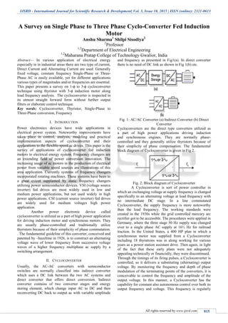
  • 1. IJSRD - International Journal for Scientific Research & Development| Vol. 3, Issue 10, 2015 | ISSN (online): 2321-0613 All rights reserved by www.ijsrd.com 815 A Survey on Single Phase to Three Phase Cyclo-Converter Fed Induction Motor Anshu Sharma1 Shilpi Sisodiya2 2 Professor 1,2 Department of Electrical Engineering 1,2 Maharana Pratap College of Technology Gwalior, India Abstract— In various application of electrical energy especially in in industrial areas there are two type of current, Direct Current and Alternating Current are used. Generally fixed voltage, constant frequency Single-Phase or Three- Phase AC is easily available, yet for different applications various types of magnitudes and/or frequencies are essential. This paper presents a survey on 1-ϕ to 3-ϕ cycloconverter technique using thyristor with 3-ϕ induction motor along load frequency analysis. The cycloconverter is inspected in its utmost straight forward form without further output filters or elaborate control technique. Key words: Cycloconverter, Thyristor, Single-Phase to Three-Phase conversion, Frequency I. INTRODUCTION Power electronics devices have wide applications in electrical power system. Noteworthy improvements have taken place in control, analysis, modeling and practical implementation aspects of cycloconverter and their applications to the flexible-speed ac drives. This paper is the survey of applications of cycloconverter fed induction motors to electrical energy system. Frequency changers are an extending field of power conversion innovation. The increasing usage of ac motors in the production of electrical power from variable speed sources are illustrations of this area application. Currently systems of frequency changers incorporated rotating machines. These systems have been to a great extent supplanted by static frequency changers utilizing power semiconductor devices. VSI (voltage source inverter) fed drives are most widely used in low and medium power applications, but not used widely in high power applications. CSI (current source inverter) fed drives are widely used for medium voltages high power application. Another power electronic device called cycloconverter is utilized as a part of high power application for driving induction motor and synchronous motors. They are usually phase-controlled and traditionally utilize thyristors because of their simplicity of phase commutation. . The fundamental guideline of this converter, conceived and patented by ~hazeltine in 1926, is to construct an alternating voltage wave of lower frequency from successive voltage waves of a higher frequency multiphase ac supply by a switching arrangement. II. CYCLOCONVERTER Usually, the AC-AC converters with semiconductor switches are normally classified into indirect converter which uses a DC link between the two AC systems and direct converter that offers direct conversion. Indirect converter contains of two converter stages and energy storing element, which change input AC to DC and then reconverting DC back to output ac with variable amplitude and frequency as presented in Fig1(a). In direct converter there is no need of DC link as shown in Fig 1(b) etc. Fig. 1: AC/AC Converter (a) Indirect Converter (b) Direct Converter Cycloconverters are the direct type converters utilized as a part of high power applications driving induction and synchronous engines. They are normally phase- controlled and they generally utilize thyristors because of their simplicity of phase compensation. The fundamental block diagram of Cycloconverter is given in Fig 2. Fig. 2: Block diagram of Cycloconverter A Cycloconverter is sort of power controller in which an exchanging voltage at supply frequency is changed specifically to an alternating voltage at load frequency with no intermediate DC stage. In a line commutated Cycloconverter, the supply frequency is more noteworthy than the load frequency. The working standards were created in the 1930s while the grid controlled mercury arc rectifier got to be accessible. The procedures were applied in Germany, where the three stage 50 Hz supply was changed over to a single phase AC supply at 16⅔ Hz for railroad traction. In the United States, a 400 HP plan in which a synchronous motor was supplied from a Cycloconverter including 18 thyratrons was in along working for various years as a power station assistant drive. Then again, in light of the fact that these early plans were not adequately appealing technically or financially, they were discontinued. Through the timings of its firing pulses, a Cycloconverter is controlled, so it delivers a substituting (alternating) output voltage. By monitoring the frequency and depth of phase modulation of the terminating points of the converters, it is conceivable to control the frequency and amplitude of the output voltage. In this manner, a Cycloconverter has the capability for constant also autonomous control over both its output frequency and voltage. This frequency is regularly
  • 2. A Survey on Single Phase to Three Phase Cyclo-Converter Fed Induction Motor (IJSRD/Vol. 3/Issue 10/2015/178) All rights reserved by www.ijsrd.com 816 under 1/3 of the given frequency. The nature of the output voltage wave and its symphonious distortion additionally force the restriction on this frequency. The distortion is low at low output frequencies. The Cycloconverters are typically used to give either a variable frequency from a constant input frequency or a constant frequency from a variable input frequency. A Cycloconverter can carry load of any power factor and permits power flow in both the directions. The output voltage wave shape definitely consist symphonious distortion parts additionally to the required sinusoidal component. These distortion terms are delivered as an important result of the fundamental mechanism of the Cycloconverter, whereby the output voltage is created from portions of the given voltage waves. These twists can be minimized by sufficient channels at the yield. Increments happen in the distortion of the output voltage if the proportion of the output and input frequency increments [1]. A. Applications Of Cycloconverter Are: - used for controlling the speed of high power AC drives - used in high frequency induction motors - used in static VAR generators - they are used as a power supplier in the aircrafts and space vehicles - used in High voltage DC(HVDC) transmission for interconnecting two power grids operating at two different frequencies. III. ADVANTAGES OF CYCLOCONVERTER 1) Conversion of frequency, directly without any intermediate stage. 2) Natural commutation – Compact system. 3) Transfer of Power in either direction. 4) Capable of reproduction over the complete speed range, down to standstill. 5) Commutation failure leads only to blown-off of individual fuses only. 6) Provides a high quality sinusoidal waveform at low output frequencies since it is created from a huge number of parts of the supply waveform. This is frequently preferable for very low speed applications. IV. OPERATING PRINCIPLE OF CYCLOCONVERTER A. Single-Phase To Single-Phase (1ϕ-1ϕ) Cycloconverter: This converter comprises of consecutive association of two full-wave rectifier circuits. Fig 3 demonstrates the working waveforms for this converter with resistive load. The input voltage vs, is an ace voltage at a frequency, Vi as showed in Fig. 3a. All the thyristors are fired up at a=0° firing angle, i.e. thyristors acts like diodes. Firing angle for positive converter is meant by αp and for negative converter αn. The frequency of Vo can be altered by shifting the number of cycles, positive and negative converters work. Consider the working of the cycloconverter to accomplish ¼ of the input frequency at the output. For the beginning two cycles of vs, the positive converter acts to giving current to the load. It rectifies the input voltage; thusly, the load found four positive half cycles as found in Fig. 3b. In the subsequent two cycles, the negative converter works giving current to the load in the opposite direction. The current waveforms are not shown in the figures due to the certainty that the resistive load current will have the similar waveform as the voltage though simply scaled by the resistance. Note that when one of the converters works the other one is impaired, so that there is no present circling between the two rectifiers. Fig. 3: (a) Cycloconverter, Single-phase to single-phase(1ϕ- 1ϕ) Fig. 3: shows cycloconverter waveforms of Single-phase to single-phase 1) Input voltage 2) Output voltage for zero firing angle 3) Output voltage with firing angle p/3 rad 4) Output voltage with varying firing angle Due to the frequency of the output, Vo in fig.3b is one fourth of the input voltage, i.e. fo/fi=1/4 that’s why it is step down cycloconverter. Instead of it, if the cycloconverter frequency has correlation like this fo/fi>1, it’s known as step-up cycloconverters. Notify that step-down cycloconverters are further commonly used in compare step- up ones. The frequency of vo can be adjust by altering the figure of cycles the positive and the negative converters works. It can only change as integer multiples of fi in 1ϕ- 1ϕcycloconverters.With the above operation, the 1ϕ- 1ϕcycloconverter can only supply a certain voltage at a certain firing angle a. The dc output of each rectifier is: (1) where V is the input r.m.s voltage. The dc value per half cycle is shown as dotted in Fig. 3d. Then the peak of the fundamental output voltage is ( ) (2)
  • 3. A Survey on Single Phase to Three Phase Cyclo-Converter Fed Induction Motor (IJSRD/Vol. 3/Issue 10/2015/178) All rights reserved by www.ijsrd.com 817 Equation 2 infers that the basic output voltage relates to a. Hence changing a, the fundamental output voltage can be controlled. Fixed operation gives a rough output waveform with rich harmonic content. The dotted lines in Fig. 3b and c demonstrate a square wave. If the square wave can be adjusted to look more like a sine wave, the harmonics would be reduced. Hence is modulated as shown in Fig. 3d. Presently, the six-stepped dotted line is more like a sine wave with fewer harmonics. The more pulses there are with different a's, the less are the harmonics. B. Three-Phase to Single-Phase (3ϕ-1ϕ) Cycloconverter: There are two types of three-phase to single-phase (3ϕ-1ϕ) cycloconverters: 3ϕ-1ϕ half-wave cycloconverter (Fig. 4) and 3ϕ-1ϕ bridge cycloconverter (Fig. 5). Like the 1ϕ-1ϕ converter case, the 3ϕ-1ϕcycloconverter applies rectified voltage to the load. Both of them, positive and negative converters can generate voltages at either polarity, however positive converter can only supply positive current and the negative converter can only supply negative current Accordingly, the cycloconverter can operate in four quadrants: (+v, +i) and (-v, -i) rectification modes and (+v, - i) and (-v, +i) inversion modes. The modulation of the output voltage and the basic output voltage are shown in Fig. 6. It seems that α is sinusoidally modulated over the cycle to generate a harmonically idyllic output voltage. Fig. 4: 3f-1f Half-Wave Cycloconverter Fig. 5: 3ϕ-1ϕ Bridge Cycloconverter Fig. 6: 3ϕ-1ϕ Half-Wave Cycloconverter Waveforms A) + Converter Output Voltage B) Cosine Timing Waves C) – Converter Output Voltage The extremity of the current defines whether the positive or negative converter should be supplying power to the load. Customarily, the firing angle for the positive converter is named aP, and that of the negative converter is named a N. At the point when the polarity of the current changes, the converter beforehand providing the current is disabled and the other one is enabled. The load continuously needs the essential voltage to be continuous. Subsequently, during the current polarity reversal, the average voltage provided by both of the converters ought to be equal. Else, switching from one converter to the next one would cause an undesirable voltage jump. To avoid this problem, the converters are forced to generate the same average voltage at all times. Accordingly, the accompanying condition for the firing angles ought to be met ……. (1) The fundamental output voltage in Fig. 6 can be given as: ( ) ……. (2) Where Vo is the rms value of the fundamental voltage At a time to the output fundamental voltage is ( ) ……. (3) The positive converter can supply this voltage if aP satisfies the following condition. Where (p=3 for half wave converter and 6 for bridge converter) From the a condition (3) The firing angles at any instant can be found from eq. The operation of the 3ϕ-1ϕ bridge cycloconverter is similar to the above 3ϕ-1ϕ half-wave cycloconverter. Note that the pulse number for this case is 6. C. Three-Phase to Three-Phase (3ϕ-3ϕ) Cycloconverter: In the occurrence that the outputs of 3-ϕ to 1-ϕ converters of the same type are associated in wye or delta and if the output voltages are 2π/3 radians phase moved from each other, the subsequent converter is a three phase to three- phase (3ϕ-3ϕ) cycloconverter. The subsequent cycloconverter are appeared in Figs. 7 and 8 with wye connections. If the three converters associated are half-wave converters, then it’s known as a 3ϕ-3ϕ half-wave cycloconverter. If instead, bridge converters are utilized,
  • 4. A Survey on Single Phase to Three Phase Cyclo-Converter Fed Induction Motor (IJSRD/Vol. 3/Issue 10/2015/178) All rights reserved by www.ijsrd.com 818 then the result is a 3ϕ-3ϕ bridge cycloconverter. 3ϕ-3ϕ half- wave cycloconverter is also known as 3-pulse cycloconverter or an 18-thyristor cycloconverter. Then again, the 3ϕ-3ϕ bridge cycloconverter is likewise called a 6-pulse cycloconverter or a 36-thyristor cycloconverter. The operation of each phase is clarified in the previous segment. Fig. 7: 3ϕ-3ϕ Half-Wave Cycloconverter Fig. 8: 3ϕ-3ϕ Bridge Cycloconverter The three-phase cycloconverter are in a general sense utilized in ac machine drive systems running three phase synchronous and induction machines. They are more beneficial when utilized with a synchronous machine due to their output power factor features. A cycloconverter can provides lagging, leading, or unity power factor loads while its input is frequently lagging. A synchronous machine can figure out any power factor current from the converter. This typical operation matches the cycloconverter to the synchronous machine. Then again induction machines can only figure out lagging current, so the cycloconverter does not have an edge paralleled with alternate converters in this facet for running an induction machine. Then again, cycloconverter are utilized as a part of Scherbius drives for speed control purposes driving wound rotor induction motors. D. Single-Phase to Three-Phase (1ϕ-3ϕ) Cycloconverters: In recent times, with the drop in the size and the cost of power electronics switches, single-phase to three-phase cycloconverters (1ϕ-3ϕ) initiating more research attention. Generally, an H -bridge inverter generates a high frequency single-phase voltage waveform, which is fed to the cycloconverter either through a high frequency transformer or not. If a transformer is used, it isolates the inverter from the cycloconverter. In further, additional taps from the transformer can be utilize to power other converters generating a high frequency ac connection. The single-phase high frequency ac (hfac) voltage can be either sinusoidal or trapezoidal. There may be zero voltage intervals for control purposes or zero voltage commutation. Fig. 9 demonstrates the circuit diagram of aordinaryhfac link converter. These converters are not commercially available yet. They are in the research state Fig. 9: High Frequency Ac Link Converter (1f Hf Inverter + (1f-3f) Cycloconverter) Cycloconverter produce harmonic rich output voltages. When cycloconverter are used to run an ac machine, the leakage inductance of the machine filters the greater part of the higher frequency harmonics and reduces the magnitudes of the lower order harmonics labels. V. LITERATURE REVIEW Xiaofeng Yang [3] presented an advance single-phase to three-phase cycloconverter appropriate for driving an induction motor. By means of discrete variable frequency system, a single-phase to three-phase modulation technique is proposed the output frequency of this cycloconverter may be up to half of the input frequency. Only six commonly communicated thyristors are employed, so the subsequent cycloconverter-motor drive framework is cheap and compact. Programming in C and assembly language has been written for real-time control. The reproduction in view of Matlab /Simulink is used to foresee the presentation for the cycloconverter and induction motor toolbar Ashwini Kadam [4] paper present is to control the speed of an induction motor by changing the frequency with three level diode clamped multilevel inverter. To get high quality sinusoidal output voltage with reduced harmonics distortion, multicarrier PWM control plan is presented for diode clamped multilevel inverter .This technique is executed through changing the supply voltage and frequency
  • 5. A Survey on Single Phase to Three Phase Cyclo-Converter Fed Induction Motor (IJSRD/Vol. 3/Issue 10/2015/178) All rights reserved by www.ijsrd.com 819 applied to the three phase induction motor at constant ratio. The proposed system is an actual replacement for the conventional strategy which delivers high switching losses, result in poor drive performance. The simulation & implementation results reveal that the proposed circuit efficiently controls the motor speed and increases the drive presented through reduction in Total Harmonic Distortion (THD). Ali S. Bathunya[5] ] in this paper deals with writings study of several existing converter topologies, which have been displayed for adjustable speed single phase induction motor drives (SPIMD).this papers explains some converter topologies which are recently used and comparison is done. Among these, converter topologies, the adjustable frequency PWM inverter is the greatest decision for single-phase induction motor drives. Regardless, adjustable-frequency drives have not been generally utilized with single-phase induction motors. The open-circle constant V/f control law can’t be utilized with the single- phase induction motor drives it is utilized with three phase motors. The variety of the working frequency at lower speed range with constant load torque sources assortmentin the motor’s slip. A constant V/f control is appropriate merely over the upper speed range. In any case, enhancements in the low frequency performance need to the utilization of constant power dissipation in the motor. Simulation lessons for several of the existing topologies in addition for the proposed once have been completed G. Sudhir Kumar [6] system combines two parallel rectifiers without the use of transformers. The control system and the, system model, with the PWM method, have been developed. The whole comparison between the proposed and standard configurations has been carried out in this work. Compared to the conventional topology, the presented system permits to lessen the rectifier switch currents, the THD of the grid current and to increase the fault tolerance features. The simulation result shows that the system is controlled suitably, with transient and event of faults. G. R. Sreehitha [7] proposed a new topology for controlling a three-phase induction motor with single-phase supply. In this work control of Cycloconverter is done by the firing pulses. With the support of variable frequencies got the variable speeds of a three-phase induction motor. The real part of a Scott-T transformer was utilized to convert two-phase, output of two Cycloconverter to three- phase Abhishek Pratap Singh [8] designed cycloconverter circuits and simulated and finally desired results were obtained. The single phase cycloconverter utilized for split phase motor to produce supply the torque features, whom matching with demand torque features of specific machine by the utilize of designing cycloconverter diverse desired frequency were obtained .to match the torque demand of the machine. This distinctive frequency of cycloconverter was suitable to replace fly wheel from the operating machine which reduce the reason of torsional vibration and fatigue damage of machine. Paper proposed criticism control scheme of cycloconverter fed split phase induction motor. Besides, it delivers mean for limiting the slip and hence the motor current. It implies a reduction in the cycloconverter rating and better efficiency. The results acquired using MATLAB for single phase cycloconverter coupled induction motor. RadhaKrishna[9] paper present a system drive through single-phase to three-phase made out of two parallel single-phase rectifiers, a three-phase inverter,an induction motor. The presented topology licenses to lessen the harmonic distortion at the input converter side, the rectifier switch currents, and displays enhancements on the fault tolerance features. Expand the number of switches, the total energy loss of the proposed system may be lower than of a conventional one. The model of the system is derived, and it is displayed that the reduction of circulating current is an essential objective in the system design. An appropriate control approach, through the pulse width modulation technique (PWM), is developed. Experimental results are presented. Kamaljeet[10] this paper present Matlab modeling and simulation of Single phase-three phases Cycloconverter for driving three phase induction motor and analysis of torque for several frequencies. The proposed converter employs just six usual communicated thyristor, therefore the resulting Cycloconverter motor drive system was cheap and compact, though this single phase to three phase modulation procedure is proposed on the premise of variable frequency method. VI. CONCLUSION A cycloconverter is a device use to convert a constant voltage constant frequency AC power to variable voltage variable frequency without any intermediate DC link. In this paper presented a survey on conversion of single phase (1-ϕ) to three phase (3-ϕ) cycloconverter fed induction motor. There are several techniques use for conversion but order to have maximum converter utilization, special cycloconverter techniques have to be used. Studies of different researchers are also presented to understand the work on single to three phase cycloconverter. REFERENCES [1] K.V.S Bharath, Ankit Bhardwaj “Implementing Single Phase Cycloconverter Using Single Phase Matrix Converter Topology with Sinusoidal Pulse Width Modulation” International Journal for Technological Research in Engineering Volume 2, Issue 6, February- 2015. [2] BurakOzpineci, Leon M. Tolbert “CYCLOCONVERTERS” http://www.uv.es/~emaset/iep00/cycloconvertertutorial .pdf. [3] Xiaofeng Yang, RuixiangHao, Xiaojie You, Trillion Q. Zheng “A New Single-Phase to Three-Phase Cycloconverter for Low Cost AC Motor Drives” 978- 1-4244-1718-6/08/$25.00 ©2008 IEEE. [4] AshwiniKadam, A.N.Shaikh “Simulation & Implementation Of Three Phase Induction Motor OnSingle Phase By Using PWM Techniques” International Journal of Engineering Research and General Science Volume 2, Issue 6, October- November, 2014.
  • 6. A Survey on Single Phase to Three Phase Cyclo-Converter Fed Induction Motor (IJSRD/Vol. 3/Issue 10/2015/178) All rights reserved by www.ijsrd.com 820 [5] Ali S. Ba-thunya Rahul KhopkarKexin Wei Hamid A. Toliyat“Single Phase Induction Motor Drives - A Literature Survey” [6] G. Sudhir Kumar, G. Kumaraswamy, Dr. K. Sri Gowri “Modeling of Single-Phase to Three-Phase Drive System Using Two Parallel Converters On Input Side” International Journal of Engineering Research and Applications (Ijera) Vol. 3, Issue 4, Jul-Aug 2013, Pp.1821-1827 [7] G. R. Sreehitha, A. Krishna Teja, Kondenti. P. Prasad Rao “Control of a Three Phase Induction Motor using Single Phase Supply” International Journal of Engineering Trends and Technology- Volume3Issue3- 2012 [8] AbhishekPratap Singh1, V. K. Giri“Modeling And Simulation Of Single Phase Cycloconverter” [Ijesat] International Journal Of Engineering Science & Advanced Technology Volume-2, Issue-2, 346 – 351 [9] Radha Krishna1, Amar kiran “Modeling of Single- Phase to Three-Phase Drive System Using Two Parallel Single-Phase Rectifiers” International Journal of Modern Engineering Research (IJMER) Vol.2, Issue.5, Sep-Oct. 2012 pp-3899-3907 [10]Kamaljeet Singh Thakur, C. S. Sharma, S. P. Phulambrikar “Modeling and Simulation of Single Phase ToThree Phase Cycloconverter for Low Cost AC Motor Drives” INTERNATIONAL JOURNAL OF INNOVATIVE RESEARCH & DEVELOPMENT Vol 3 Issue 5 May2014.