Weitere ähnliche Inhalte
Ähnlich wie Sackmann 2014
Ähnlich wie Sackmann 2014 (20)
Kürzlich hochgeladen (20)
Sackmann 2014
- 1. REVIEW doi:10.1038/nature13118
The present and future role of
microfluidics in biomedical research
Eric K. Sackmann1
, Anna L. Fulton2
& David J. Beebe3
Microfluidics, a technology characterized by the engineered manipulation of fluids at the submillimetre scale, has shown
considerable promise for improving diagnostics and biology research. Certain properties of microfluidic technologies,
such as rapid sample processing and the precise control of fluids in an assay, have made them attractive candidates to
replace traditional experimental approaches. Here we analyse the progress made by lab-on-a-chip microtechnologies in
recent years, and discuss the clinical and research areas in which they have made the greatest impact. We also suggest
directions that biologists, engineers and clinicians can take to help this technology live up to its potential.
M
ore than a decade ago, we wrote that ‘‘microfluidics has the
potential to significantly change the way modern biology is
performed’’1
. Indeed, we were part of a chorus of researchers
that recognised the possibility of new microfluidic tools making sub-
stantial contributions to biology and medical research2–5
. The optimism
surrounding microfluidics was well warranted, given the compelling
advantages that microfluidic approaches could possibly have over tra-
ditional assays used in cell biology. Conceptually, the idea of microflui-
dics is that fluids can be precisely manipulated using a microscale device
built with technologies first developed by the semiconductor industry
and later expanded by the micro-electromechanical systems (MEMS)
field. These devices, commonly referred to as miniaturized total analysis
systems (mTASs)6,7
or lab-on-a-chip(LoC) technologies, could be applied
to biology research to streamline complex assay protocols; to reduce the
sample volume substantially; to reduce the cost of reagents and maximize
information gleaned from precious samples; to provide gains in scalabi-
lity for screening applications and batch sample processing analogous to
multi-well plates; and to provide the investigator with substantially more
control and predictability of the spatio-temporal dynamics of the cell
microenvironment.
The field of microfluidics is characterized by the study and manipu-
lation of fluids at the submillimetre length scale. The fluid phenomena
that dominate liquids at this length scale are measurably different from
those that dominate at the macroscale (Box 1). For example, the relative
effect of the force produced by gravity at microscale dimensions is greatly
reduced compared to its dominance at the macroscale. Conversely, sur-
face tension and capillary forces are more dominant at the microscale;
these forces can be used for a variety of tasks, such as passively pumping
fluids in microchannels8
; precisely patterning surfaces with user-defined
substrates9
; filtering various analytes10
; and forming monodisperse drop-
lets11
in multiphase fluid streams for a variety of applications. These
examples represent only a fraction of the myriad problems that micro-
fluidic technologies have attempted to address.
The development of comprehensive microfluidic solutions to address
problems in biology and clinical research has been embraced by engi-
neers. However, despite material advances in microfluidics as a techno-
logy platform, the adoption of novel mTAS techniques in mainstream
biology research has not matched the initial enthusiasm surrounding
the field12
. Some argue the technology is still in search of a ‘killer applica-
tion’, wherethesample-to-answerconceptprovidesasolutionthatgreatly
outperformscurrent methods13,14
.Inthisperspective,wewill examinethe
impact of microfluidic technologies on cell biology and medical research
within the past decade. We discuss some of the barriers to adoption of
microfluidic technologies in mainstream biomedical research, and use
a case study to illustrate and highlight these challenges. We focus our
attention on recent developments in the field that are facilitating the
application of microfluidic technologies to solving problems in diagnost-
ics and biology research. In this area, we highlight the innovative use of
different materials that are more optimally suited to performing a given
task; and we examine how researchers are taking advantage of mTAS
methods to enable scientific inquiry in ways that were not possible using
traditional methods. Finally, we will discuss positive trends in the field
and infer lessons that can be applied to future microfluidic technology
development.
The impact of microfluidics on biomedical research
A primary goal for much of the microfluidics community is to develop
technologies that enhance the capabilities of investigators in biology and
medical research. Many microfluidic studies describe methods that aim
to replace traditional macroscale assays, and usually perform proof-of-
concept (PoC) experiments that attempt to demonstrate the efficacy of
the new approach. These novel microfluidic methods are usually pub-
lished in journals that might be characterized as ‘engineering’ journals,
or publications whose readership comprises largely engineers and other
members of the physical sciences (for example, chemists and physicists).
If publishing PoC studies in engineering journals represents the devel-
opment phase for a novel biology assay, then the implementation of the
technique can be characterized as when the technology is used and pub-
lished in a biology or medical journal. After all, the stated goal of vir-
tually all PoC studies is to demonstrate new technologies that enable
biologists in their everyday research.
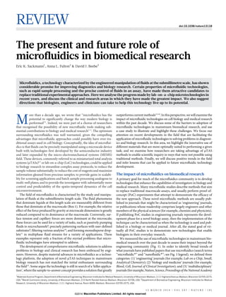
We measured the use of microfluidic technologies in mainstream bio-
medical research over the past decade to assess their impact beyond the
engineering community (Fig. 1). In order to identify broad trends of
what journals have published papers that use microfluidics (search terms
‘‘microfluidic*’’ and ‘‘nanofluidic*’’; see Fig. 1 legend), we defined three
categories: (1) ‘engineering’ journals (for example, Lab on a Chip, Small,
Analytical Chemistry); (2) ‘biology and medicine’ journals (for example,
Blood, Cell, Journal of Clinical Investigation); and (3) ‘multidisciplinary’
journals(forexample,Nature,Science,ProceedingsoftheNationalAcademy
1
Materials ScienceProgram, Department ofBiomedical Engineering,Wisconsin Institutesfor MedicalResearch, University of Wisconsin-Madison, 1111Highland Avenue,Madison, Wisconsin 53705-2275,
USA. 2
Wendt Commons Library, University of Wisconsin-Madison, 215 North Randall Avenue, Madison, Wisconsin 53706, USA. 3
Department of Biomedical Engineering, Wisconsin Institutes for Medical
Research, University of Wisconsin-Madison, 1111 Highland Avenue, Room 6009, Madison, Wisconsin 53705-2275, USA.
1 3 M A R C H 2 0 1 4 | V O L 5 0 7 | N A T U R E | 1 8 1
Macmillan Publishers Limited. All rights reserved©2014
- 2. ofSciences).Theresultsreveal,unsurprisingly,thattheoverwhelmingnum-
ber of microfluidics papers are still being published in engineering journals
(Fig. 1a). These engineering journals have facilitated the technological de-
velopment and growth of microfluidics over the past decade.It is important
to note that some of these ‘engineering’ studies may have been designed
for non-biomedical purposes, but this does illustrate where the majority
of microfluidic activity and exposure has occurred. Today the majority
of microfluidics publications still appear in engineering journals (85%) as
the microfluidics community has grown substantially, and ‘biology and
medicine’ journals have taken some publication share from interdiscip-
linary journals (9% and 6%, respectively).
2000
2001
2002
2003
a
b
2004
2005
2006
Year
2007
2008
2009
2010
2011
2012
~130
Numberofpublications
Numberofpublications
cell biology
biology
pathology
oncology
reproductive biology immunology
peripheralvasculardisease
microbiology
cardiacandvascularsystems
haematology
medicine and exp. research
virology
respiratory system
neurosciences
physiology
medical laboratory technology
toxicology
Microfluidics in engineering journals
Microfluidics in multidisciplinary journals
Microfluidics in biology and medicine journals
80%
6%
14%
infectiousdisease
~1,200
85%
6%
9%
Figure 1 | Microfluidic publications in engineering, multidisciplinary, and
biology and medicine journals from 2000 to 2012. a, In 2012, there were
roughly 10 times more microfluidic publications in engineering journals
compared to biology and medicine (biomedical) journals (left-hand pie chart
inset). However, the share of microfluidics papers being published in
multidisciplinary journals decreased as publication share in biomedical and
engineering journals increased (right-hand pie chart). b, Word cloud
illustrating what fields most frequently used microfluidics. The size of the
font is proportional to the cumulative number of publications in the Web of
Science (WoS) category (2000–12), with the exception of ‘cell biology’,
which would need to be ,5 times larger. Methodology of the searches was
as follows. A literature search was performed using WoS (provided by
Thomson Reuters) to determine the number of microfluidics publications in
various disciplines. The search was performed for the terms ‘‘microfluidic*’’
and ‘‘nanofluidic*’’. The number of publications were obtained from the WoS
analytics reporting system for each search term, and then summed before
being presented above. Three categories were characterized by the WoS search
that capture the relevant journals for the years 2000–12. The analysis shown
here as ‘‘Microfluidics in engineering journals’’ reports the number of
microfluidic publications in the ‘Nanoscience and nanotechnology’ WoS
category. The analysis shown here as ‘Microfluidics in multidisciplinary
journals’ corresponds to the ‘Multidisciplinary’ WoS category. The analysis
shown here as ‘Microfluidics in biology and medicine journals’ reports
publications from WoS categories shown in Fig. 1b. The search explicitly
excluded ‘reviews’, ‘book chapters’, ‘book reviews’, ‘meeting abstracts’, ‘meeting
summaries’, and included ‘articles’. The data shown reflects the most
recent literature search, performed on 21 March 2013. The following
search general string was used: Topic 5 (microfluidic*) AND Year
Published 5 (2000-2012) AND Document Types 5 (Article) NOT
Document Types 5 (Book OR Book Chapter OR Book Review OR Meeting
Abstract OR Meeting Summary OR Proceedings Paper OR Review). This
string yielded the total ‘microfluidic*’ publications in all WoS categories
(‘*’ allows for permutations of the keyword). The search was then refined
by the WoS categories shown above (for example, Web of Science
Categories 5 (MULTIDISCIPLINARY). Importantly, the nominal results
of this search would probably vary if other search tools such as SCOPUS,
Google Scholar and PubMed were used98,99
. For example, the gross number of
publications would probably increase if SCOPUS were used for the search,
as this tool indexes a higher number of journals than WoS99
.
BOX 1
Useful microfluidics concepts
Laminar versus turbulent flow. The Reynolds number (Re) is a
dimensionless quantity that describes the ratio of inertial to viscous
forces in a fluid. Re is proportional to the characteristic velocity of the
fluid and the length scale of the system; it is inversely proportional
to the fluid viscosity. High-Re (,2,000) fluids have flow profiles
that increasingly mix stochastically (turbulent flow; Box 1 Figure
below). For microfluidic systems, Re is almost always in the laminar
flow regime, allowing for highly predictable fluid dynamics. Molecular
transport also changes dramatically at this scale because convective
mixing does not occur, enabling predictable diffusion kinetics.
Surface and interfacial tension. Surface tension describes the
tendency of a fluid in a surface to reduce its free energy by contracting
at the surface–air interface. Interfacial tension is a similar
phenomenon, but is generally applied to two immiscible fluids (for
example, oil and water). These forces play more dominant roles on
the microscale (Box 1 Figure below) compared to gravity, which is
much more dominant on the macroscale. Researchers have used
these phenomena to conduct protein and cell sorting, perform
nanoreactions for protein crystallization, and passively drive fluids
through microchannels.
Capillary forces. Capillary action describes the movement of a fluid
through a narrow constriction, such as a narrow tube or porous
material (Box 1 Figure below). At the microscale, capillary action is a
more dominant force, allowing fluids to advance in opposition to
gravity. Capillary forces have been used to manipulate fluids in
many applications, the most famous examples perhaps being the
at-home pregnancy test and portable glucometers to monitor blood
glucose levels.
Laminar flow Turbulent flow
Laminar versus turbulent flow
Oil
Liquid (for example, water)
Water
Surface and interfacial tension
Liquid
Liquid
Paper
Capillary forces
RESEARCH REVIEW
1 8 2 | N A T U R E | V O L 5 0 7 | 1 3 M A R C H 2 0 1 4
Macmillan Publishers Limited. All rights reserved©2014
- 3. Last, we analysed what fields within the biomedical research commu-
nity are using microfluidic technologies the most (Fig. 1b). ‘Cell biology’
and ‘Biology’ encompass most of the microfluidics publications, possibly
because these categories are somewhat generic and incorporate several
subcategories. Following these, the most use of microfluidics is seen in
‘Haematology’, ‘Medicineandexperimentalresearch’ and‘Immunology’.
Most of these publications are for diagnostic applications (in the case of
Medicineandexperimentalresearch)andthemanipulationofbloodsam-
ples for biology research (Haematology and Immunology)—applications
wheremicrofluidicshascompellingadvantages overtraditional methods.
However, despite these few examples, the evidence suggests that a ‘killer
application’thatpropelsmicrofluidicsintothemainstreamhasyettoemerge.
A case study in chemotaxis assays
The state of the art for most conventional assays used in cell biology
research is evolving and improving over time. Biologists understand
better than anyone the deficiencies of the techniques they use, and indi-
vidual groups occasionally make modifications to traditional assays that
are adopted more broadly by other biology researchers. An example of
thistechnologicalevolutioncanbeobservedinvisualchemotaxisassays—
techniquesthatmeasure the directionalmigrationofa cellinresponsetoa
sourceofchemotacticfactorsthatchangeconcentrationinspaceandtime.
Chemotaxis assays haveimproved substantiallysince their initial intro-
duction in the 1960s (Fig. 2). The most widely used chemotaxis assay is
knownasthe‘Boyden chamber’or‘Transwell’assay,developedin1962by
Boyden15
. The Transwellassay works bycreating a concentration gradient
of chemoattractant compounds between two wells that are separated by
amicroporousmembrane.Chemotacticcellslocatedintheupperwellsense
the gradient in concentration and migrate across the membrane towards
the solution in the lower well where the cells are counted. Its simplicity
and ease of use (no special instrumentation is required) has contributed
to its widespread use over the past 50 years. Investigators have used the
method to identify chemotactic factors for various cell types, despite the
fact that the technique disallows observation of the cell migration path
or cell morphology. This experimental limitation (along with others) led
to the development of visual chemotaxis assays such as the Zigmond
chamber16
. In this system, cells can be observed as they undergo chemo-
taxis on a coverslip across a narrow constriction (tens of micrometres)
towards a source chemoattractant. It is worth noting that the Zigmond
chamber is a microfluidic device developed by biologists at least a decade
before the emergence of the microfluidic/mTAS field as we know it. Im-
portantly, this technique allows for clear imaging of cell migration and
morphology. Modifications to this design, called the Dunn17
and Insall18
chambers, were subsequently developed, and these advances substan-
tially improved the high-resolution, long-term imaging capabilities of
visual chemotaxis assays (Fig. 2). The Insall chamber represents the most
recent of a long evolution of direct-viewing chemotaxis chambers that
have been developed over the course of three decades.
Microfluidics has offered many solutions for next-generation chemo-
taxis assays (reviewed in refs 19 and 20); however, none of these methods
have seen widespread adoption at the level of the aforementioned tra-
ditional assays. Additionally, efforts to commercialize microfluidic che-
motaxis assays—notable products include m-Slide Chemotaxis (ibidi),
IuvoChemotaxisAssayPlate(BellBrookLabs),andEZ-TAXIScan(Effec-
tor Cell Institute)—have had limited success in the marketplace. The
generation of chemical gradient profiles is an area where microfluidic
technologies are uniquely qualified because of the highly predictable21
,
diffusion-dominant characteristics of the fluid flow at this scale (Box 1).
Yet traditional assays are still predominantly used for chemotaxis studies
in cell biology research. The low adoption rate of microfluidic chemotaxis
assays may be due to the fluid handling expertise and infrastructure
required in early designs22,23
, which may have acted as a barrier to entry
for biologists24
. Recently published microfluidic chemotaxis techniques
are beginning to take usability requirements into consideration, and de-
monstrate simpler chemotaxis assay designs that do not require active
pumpingsystems25–27
.Anotherpossibilityisthatbiologistsaremorecom-
fortablewithusingtheexistingdirect-viewingchemotaxisassaysthathave
been developed and vetted over nearly 40 years (Fig. 2). Notably, each
iterative improvement on the Zigmond chamber design was published
by investigators with appointments in biology (Zigmond); experimental
pathology (Boyden and Dunn); and cancer research (Insall)—none of the
designs were produced from ‘engineering’ disciplines. These technical
advances were made by biologists to address unmet needs in their own
research. And in the case of visual chemotaxis, the methods were, in fact,
microfluidic by any reasonable definition, yet they are not typically in-
cluded within the microfluidic vernacular. In the case of chemotaxis
assays, engineers have sometimes erred by imposing technological com-
plexity and functionality where it was not necessarily needed or wanted.
This case study illustrates the continuing need for engineers and biolo-
giststoworkcloselyduringassaydevelopmenttocreateusable androbust
solutions that build on biologically validated approaches, while adding
functionality that allows new avenues of biological inquiry.
Materials tailored for specific applications
Unlike the semiconductor industry where silicon is the backbone mater-
ial on which the technology has been built28,29
, the materials used for
developing microfluidic devices have undergone a large transition over
the years. Early mTAS devices were fabricated from silicon30
and glass31
using clean-room techniques that were translated to microfluidic device
fabrication.Thiswaslargelyachoiceof convenience(becausethe techniques
Development of microfluidic visual chemotaxis assays
Development of traditional chemotaxis assays
1960 1970 1980
Year
1990 2000
Boyden chamber (1962) Zigmond chamber (1977) Dunn chamber (1991) Insall chamber (2010)
Still widely used today
Direct-viewing chemotaxis
Concentric ring
geometry Square geometry
Cells migrate over “bridge”
through narrow constriction.
Convection from evaporation
First in vitro chemotaxis assay
Non-visual readout
Thick cover slips
Glass instead of PMMA
No high-res. imaging
Thin cover slips
PMMA with supports
Sealed for long–term
experiments>2,000 citations
Poor reproducibility of gradient
profile.
Cells
Filter
Medium and
chemo-
attractant
Figure 2 | The development of
visual chemotaxis assays over time.
The Boyden chamber assay was the
first popular in vitro chemotaxis
technique. The Zigmond chamber
design has undergone several
evolutionary changes (Dunn and
Insall chambers) to address problems
with previous versions of the assay.
Note the relatively short time for
which microfluidics techniques have
been available in comparison to the
classical visual chemotaxis assays
(bars on the timeline compare the
development of visual chemotaxis
assays). Chamber images adapted
with permission from ref. 100,
Nature Publishing Group (Boyden
chamber) and from ref. 18.
REVIEW RESEARCH
1 3 M A R C H 2 0 1 4 | V O L 5 0 7 | N A T U R E | 1 8 3
Macmillan Publishers Limited. All rights reserved©2014
- 4. and facilities were already in place) and necessity (early microfluidics
focused largely on electrophoretic phenomena where glass is a preferred
material), but not a long-term solution for cell biology research. Silicon is
opaque to visible and ultraviolet light, making this material incompatible
with popular microscopy methods. Glass and silicon are both brittle
materials, they have non-trivial bonding protocols for closing micro-
channels, and in general they require expensive, inaccessible fabrication
methods. These materials were well suited for some applications (for
example, electrophoresis), but were ultimately limited in their growth
potential. Cheaper, more accessible materials and fabrication methods
were needed to fuel the growth of microfluidic technology development
and adoption.
Elastomeric micromoulding techniques were developed by Bell Labs
in the 1970s32
, and first applied to microfluidics and cell biology in the
1980s33
. In 1998, Whitesides used polydimethylsiloxane (PDMS)—an
optically transparent, gas- and vapour-permeable elastomer— for the
fabrication of more complex microfluidic devices34
and helped ‘soft
lithography’ become the most widely adopted method for fabricating
microfluidic devices. It would be hard to exaggerate how important and
enabling PDMS has been for microfluidics, contributing to the growth of
the field in bothtechnological development and numberof publications35
.
Adoption of the material can be attributed to several key factors, includ-
ing (1) the relatively cheap and easy set-up for fabricating small numbers
of devices using PDMS in a university setting; (2) the ability to tune the
hydrophobic surface properties to become more hydrophilic36,37
; (3) the
ability to reversibly and (in some cases) irreversibly bond PDMS to glass,
plastic, PDMS itself, and other materials; and (4) the elasticity of PDMS,
which allows for easy removal from delicate silicon moulds for feature
replication. Inaddition to the practical fabrication considerations of using
an elastomer, there are also useful functional advantages. Researchers
have used the elasticity of PDMS to create micropillar arrays that assay
the mechanobiology of various cell types38,39
. However, perhaps most im-
portantly, the elasticity of PMDS allows for valving and actuation40,41
,
which has led to a plethora of microfluidic designs and publications.
Fluidigm—the largest commercial mTAS technology company currently
in the market—build their microfluidic systems using deformable elas-
tomers (NanoFlex valves).
Despite all the beneficial properties of PDMS that enabled its rapid
adoption amongst university engineers, there are several limitations to
implementing the material in biomedical research. For example, PDMS
has been found to leach uncrosslinked oligomers from the curing pro-
cess into solution42
, requiring additional device preparation to mitigate
this potentially harmful effect43
. Additionally, PDMS has been shown to
absorb small molecules42,44
, which can affect critical cell signalling dyna-
mics. Furthermore, the vapour permeability of PDMS means that evap-
oration can occur in an experiment45
, which can be detrimental for cell
microenvironments at micro- and nanolitre fluid volumes46,47
. Strategies
suchasparylenecoatingthemicrochannelsurface48
andothertechniques49,50
have been developed to mitigate these problems, but these processes are
consequences of deploying a non-ideal material for cell biology applica-
tions—the often cited ‘biocompatability’ of PDMS appears to be some-
thing of a misnomer. Last, the manufacture and distribution of PDMS
devices to collaborators is not easily scalable, because high-throughput
methods such as injection moulding, rolling and embossing cannot be
used for PDMS devices. Thus, making PDMS prototypes for iterating on
a new design concept is relatively easy, but making many of these devices
andpackagingthemforcollaboratorsorcommercializationisnon-trivial51
.
Given these limitations, clearly PDMS is not a one-size-fits-all material for
all microfluidic applications, and particularly for cell biology research52
.
The limitations of PDMS have prompted researchers to explore alter-
native materials in recent years (Fig. 3). In the microfluidics community,
there has been a push towards the use of thermoplastics such as poly-
styrene and cyclic olefin copolymer53
for microfluidic devices (Fig. 3A),
although some research laboratories have always used these materials in
lieu of PDMS54,55
. Thermoplastic materials such as polymethyl metha-
crylate and polycarbonate56,57
were popular for the fabrication of mTAS
ThermoplasticsA
B
a
b
c
d
C
Paper
Wax
[Glucose]
(mM)
[BSA]
(μM)
500
50
10
5.0
2.5
75
7.5
1.5
0.75
0.38
0
0.5 cm
0
1 cm
2.1 mm
Figure 3 | Materials other than PMDS arebeingused for microfluidic device
design. A, Several research groups have demonstrated accessible methods
of thermoplastic microfluidic device fabrication. Examples of various
microfluidic designs fabricated in polystyrene are shown. B, C, Paper (B),
and to a lesser extent, wax (C) are being used in the developing world for
diagnostic applications owing to benefits in device cost, operation and
destructibility with limited waste infrastructure. B, An example of a
paper-based microfluidic device for detecting glucose and protein. The
integrity of the hydrophilic patterning is shown with a red dye (a); the detection
zones for glucose (circular region on left) and protein (square region on
right) are also shown (b); and representative tests detecting a single
concentration (c) and multiple concentrations (d) of protein and glucose
from an artificial urine sample are also shown. C, An example of a wax
microfluidic device (zoomed view in inset) that can perform an enzymatic
immunoassay. Figure sources, used with permission: A, ref. 59; B, ref. 64;
C, ref. 101. B is adapted with permission from Martinez, A. W., Phillips, S. T.,
Whitesides, G. M. & Carrilho, E. Diagnostics for the developing world:
microfluidic paper-based analytical devices. Analytical Chemistry 82,
3–10 (2010). Copyright (2010) American Chemical Society.
RESEARCH REVIEW
1 8 4 | N A T U R E | V O L 5 0 7 | 1 3 M A R C H 2 0 1 4
Macmillan Publishers Limited. All rights reserved©2014
- 5. devices in the90s, but lost favour with researchers because thefabrication
methods were more difficult and expensive than those of PDMS for the
typical academic laboratory. However, the microfluidics community has
addressed this issue by developing more accessible fabrication methods
for thermoplastic mTAS devices58–60
, although these techniques are not
without limitations35,61
. We have recently argued that polystyrene should
be preferred over PDMS for many cell biology applications, particularly
because biologistshave a long historyof using polystyrene for cell culture35
.
Furthermore, the use of polystyrene mitigates or eliminates many mater-
ial property issues associated with PDMS, including the bulk absorption
of small molecules and evaporation through the device, and polystyrene
makes handling and packaging easier for use in collaborations.
In addition to thermoplastic materials, there has been substantial pro-
gress in using destructible, cheap materials such as paper (Fig. 3B), wax
(Fig. 3C) and cloth62
for point-of-care applications in low-resource set-
tings. These materials have the benefit of being cheap and easily incin-
erated63
, making them ideal choices for settings where safe disposal of
biological samples is challenging3,64
. Currently there is increasing acti-
vity in developing microfluidic paper-based analytical devices (mPADs).
ThesemPADdevicesareexpansionsontried-and-testedlateralflowassays
(for example, pregnancy strip test) and operate by passively wicking bio-
logicalsamplesthroughpatternedhydrophilicregionsusingcapillaryforces;
they often use colorimetric readouts. The hydrophobic channel patterning
can be accomplished using a variety of methods, such as wax printing65
,
photolithographic patterning of photoresist66
, inkjet printing of PMDS67
,
and flexographically printed polystyrene68
. mPAD devices are becoming
increasingly sophisticated69,70
, with a recent study demonstrating a single-
step enzyme-linked immunosorbent assay (ELISA) for the detection of
human chorionic gonadotropin71
.
The movement beyond PDMS with the use of thermoplastics and
other materials is a positive development for the microfluidics commu-
nity. Rather than solely relying on PDMS for device fabrication regard-
less of its limitations, researchers are beginning to consider new materials
that more suitably meet the requirements of biological assays and are
amendable to high-throughput manufacturing. The shift to materials
beyond PDMS enables researchers to more effectively export technolo-
gies in scale, and allows for new solutions to problems in performing cell
biology and diagnostic assays. However, different materials often require
a re-thinking of component design. For example, it is difficult to imple-
ment the displacement valves and pumps so ubiquitous in PDMS devices
in other non-elastic materials. Therefore, technological progress using
alternative materials will require creative new approaches from engineers
that design powerful and user-friendly mTAS devices.
When mTAS technologies are the only solution
Most of themicrofluidic technologies thatwere developed for cell biology
applications in the early 2000s sought to improve on existing macroscale
assays. Many of these technologies delivered on the promised perform-
ance improvements, yet were never adopted by mainstream biology
researchers. Another possible reason for this lack of adoption, beyond
those we have previously discussed, is that these technologies are im-
provements on established techniques. Although microfluidic methods
may in some cases be technologically superior, they are often only iter-
ativeimprovements on methods that already exist.Someoneinterested in
performing protein analysis might conduct a western blot or ELISA. To
study cell chemotaxis, a researcher might perform a Transwell assay. To
investigatetissueregenerationafterawound,aninvestigatormightscratch
some cells with a micropipette tip and see what happens. Microfluidic
techniques exist that perform many of these assays with equivalent or
improved performance24
, but they have not offered fundamentally new
capabilities compared to the current state-of-the-art.
Within the past several years there have been a growing number of
microfluidic technologies that solve problems that have not yet been
addressed by macroscale approaches. Two recognizable examples that
embody this distinction can be found in the glucometer and the preg-
nancy test (or more broadly, lateral flow assays). Each test passively wicks
bodily fluids into porous materials, either blood (glucometer) or urine
(pregnancy test), and performs a previously complex biochemical assay
in a single step to provide an immediate measurement. Although there
were benchtop assays that could perform these tasks, the portability and
rapid feedback these assays provided was transformative for the end user.
There are currently applications like these for which microfluidic meth-
ods have demonstrable advantages over traditional methods. These vari-
ous applications share overlapping qualities that make them potentially
usefultechniques.However,forthepurposeofthisdiscussion,wewillbreak
them into three categories: diagnostic devices for low-resource settings;
the rapid processing of biofluids for research and clinical applications;
and more physiologically relevant in vitro models for drug discovery,
diagnostics and research applications.
Diagnostics for low-resource settings
The western model of centralized laboratories processing clinical sam-
ples with expensive equipment does not translate well to the developing
world. Many low-resource settings do not have the means or infrastruc-
ture to perform these tests and analyses, necessitating creative alternative
solutions to meet this largely unsolved problem. Microfluidic methods
are being developed to perform a variety of diagnostic tests with built-in
analysis capabilities that are compatible with the infrastructure in the
developing world (Fig. 4).Asdiscussed earlier,newmaterialsystems such
as paper, wax and others are being explored in this area53,64,72
. Common
themes with these devices include being ultra-simple to operate and the
provision of some qualitative orquantitative output thatcanbe measured
with low-cost and ubiquitous equipment (for example, a mobile-phone
camera or scanner). Also, ideally, the materials used to make the devices
are easily destructible to avoid unsafe contamination, and are cheap and
scalableto manufacture (preferably locally). Ina recent study, Chin etal.73
aimed to meet these requirements in a microfluidic chip that performs an
ELISA-like assay within ,20 minutes using volumes of blood that can be
obtained from a lancet puncture (Fig. 4). Importantly, the assay did not
require external pumping systems; it emphasized straightforward opera-
tion; and it used cheap photodetectors for the rapid optical readout. The
authors analysed more than 70 blood samples obtained from a hospital
in Rwanda and successfully diagnosed human immunodeficiency virus
(HIV) in all but one patient, achieving sensitivity and specificity values
that rival a laboratory-based ELISA test. This study and others are prom-
ising indications that mTAS technologies could make meaningful con-
tributions to healthcare in the developing world.
Low cost is arguably the most important feature when aiming to
increase access to diagnostics in the developing world, but it is also an
increasingly important factor in the developed world. If we can achieve
appropriate performance/cost combinations for the developing world,
many believe that these technologies will play an important role in
transforming the way medicine is delivered in the developed world by
enablingin-hometestingandtreatment.However,traditionallateralflow
assays achieve a low-cost/high-performance benchmark, and thus re-
present a high standard against which new approaches are compared.
Rapidly assaying biofluids with microfluidics
Engineers have made use of properties unique to the microscale to
enable studies that would be difficult or impossible using macroscale
approaches (Fig. 5). These methods have found clinical applications,
because they use ultra-low volumes of biofluids for the sample proces-
sing and can usually be accomplished rapidly and easily. To some degree
these assays mimic what macroscale assays accomplish, but the methods
offer new approaches that enable fundamentally new applications. For
example, the rapid purification and analysis of neutrophils—the phago-
cytotic cells that are first responders for the innate immune system—
have been demonstrated in several studies in recent years for clinical and
research applications26,74,75
. Importantly, these techniques reduce blood
processing times from roughly an hour (using millilitres of blood from a
venipuncture76
) to a few minutes (using only microlitres of blood from a
finger prick). Thus, the methods can be applied to measure neutrophil
REVIEW RESEARCH
1 3 M A R C H 2 0 1 4 | V O L 5 0 7 | N A T U R E | 1 8 5
Macmillan Publishers Limited. All rights reserved©2014
- 6. function for diagnostic and research purposes, enabling a new class of
studies that have previously been beyond the capabilities of macroscale
methods26
. Other purification schemes have been developed that take
advantage of the increased dominance of surface tension at the micro-
scale to sort target analytes in biofluids across multiphase barriers (for
example, oil and water; see Box 1) using fast and simple procedures77,78
.
Not only is this purification scheme simpler and faster than most macro-
scale methods, but improved sensitivities for protein and genetic pur-
ifications may be achievable owing to a reduction in the number of wash
cycles required to carry out an experiment. These applications are only
some of the examples where microscale benefits are being used to per-
form experiments that are not reasonably achievable using macroscale
techniques.
More physiologically relevant in vitro models
The pharmaceutical industry is currently faced with unsustainable re-
search and development (R&D) costs79,80
that require it to change how
the development and approval of new drugs are pursued81–83
. The indus-
tryfaces multipleheadwinds, such as theexclusivity onblockbuster drugs
soon expiring for several companies, and dramatically fewer new drugs
being approved by the Food and Drug Administration (FDA) in recent
years. These circumstances necessitate new strategies for drug develop-
mentthatincreaseR&Dproductivityinordertoavoidapotentialdrought
in effective new drugs coming to market.
Microfluidics researchers are taking aim at this problem by develo-
ping potentially transformative technologies to mitigate the cost of new
drug development. A new class of microfluidic devices seeks to replicate
in vivo organ function on a microchip (Fig. 6). This new class of so called
‘organ-on-a-chip’ technologies integrates several well-understood micro-
fluidic components into a single in vitro device, allowing researchers to
morecloselyrecapitulateinvivofunction(bothnormalanddiseasestates).
Thisambitiouseffortisstillinitsinfancy,thoughseveralpromisingstudies
have developed examples of these biomimetic systems. Examples of organ
(or disease)-on-a-chip technologies include gut-on-a-chip84
, lung-on-
a-chip85
, blood vessel-on-a-chip86–88
, cancer-on-a-chip89–91
and kidney-
on-a-chip92
. Furthermore, these modular systems could theoretically be
combined into a complete ‘human-on-a-chip’ model that mimics in vivo
function of these organs working in concert93
. The result would be a class
a b
1 mm Tape
Channel
Channel
Photoresist
in paper
Channel Cellulose powder
1 cm
t = 0.2 min t = 2 min t = 4 min
To vacuum (syringe)
Air spacers
Detection zones Outlet
Flow direction
Top view
Inlet Outlet
Sample
Buffer
wash
Au-label
antibody
Buffer
wash Water
washSide view
Lead
wash
Silver
reagents
Figure 4 | Diagnostics in the developing world. These are excellent
examples of exploiting the benefits of mTAS technologies where classical
(Western) diagnostic paradigms fail. a, A user-friendly cartridge to perform
enzyme-linked immunosorbent assays (ELISAs) for the diagnosis of HIV
and other diseases. A schematic showing the functional steps of the assay is
shown on the left andthemicrofluidic deviceis shownon theright. b, 3DmPAD
showing complex fluid handling operations that occur passively in a paper
device for diagnostics in resource-limited settings. The example shows the flow
of several coloured dyes in a patterned mPAD device, with a cross-section of
the 3D structure also shown. Figure sources, used with permission: a, ref. 73;
b, ref. 64. b is reprinted with permission from Martinez, A. W., Phillips, S. T.,
Whitesides, G. M. & Carrilho, E. Diagnostics for the developing world:
microfluidic paper-based analytical devices. Analytical Chemistry 82, 3–10
(2010). Copyright (2010) American Chemical Society.
a
1
2
3
4
4 mm
14 mm
b
Figure 5 | Rapid purification microfluidic systems. a, A microfluidic device
to purify neutrophils within minutes using antibody-based capture for
subsequent diagnostic or research analysis. The microfluidic device is shown at
the upper left with stained neutrophils that have been sorted from whole blood
below (scale bar 5 20 mm); an illustration of the neutrophils captured within
the microchannels by antibodies (zoomed view in inset) is also shown. b, A
technique to purify target analytes such as RNA, cells and proteins by simply
sliding a magnet across an immiscible aqueous–oil interface. An example
shown here illustrates four steps to purify protein from a sample (zoomed view
to the right shows detail) by (1) removing the analyte bound to paramagnetic
particles across the first aqueous-oil barrier, (2) binding a primary antibody to
the analyte and dragging it across another aqueous-oil barrier, (3) binding a
fluorescently labelled secondary antibody to the complex and bringing it across
another aqueous-oil barrier into the imaging well (4), where the fluorescence is
measured to detect the amount of analyte (white and grey fluorescent image).
Figure sources, used with permission: a, ref. 74; b, ref. 10. b is adapted with
permission from Berry, S. M., Maccoux, L. J. & Beebe, D. J. Streamlining
immunoassays with immiscible filtrations assisted by surface tension.
Analytical Chemistry 84, 5518–5523 (2012). Copyright 2012 American
Chemical Society.
RESEARCH REVIEW
1 8 6 | N A T U R E | V O L 5 0 7 | 1 3 M A R C H 2 0 1 4
Macmillan Publishers Limited. All rights reserved©2014
- 7. of sophisticated in vitro assays with which drugs could be tested, in the
hope of increasing the predictability of a new drug (that is, hit rate) before
animal testing (possibly even replacing animal trials) and human clinical
trials. In a tangential application, blood vessel-on-a-chip devices have
already been used for the diagnosis of sickle cell disease in the clinic86,94
.
For example, Tsai et al.86
described a microfluidic chip that recapitulated
in vivo conditions of a blood vessel—such as blood flow rate, endothelial
cell shear stress and biochemical activation states—in order to reliably
detectvascular occlusions due tosickle-cell disease. This systemhighlights
how certain properties of microfluidic systems, such as high-resolution
micropatterning and precise control of the haemodynamic and shear
profiles in the microchip, enabled the measurement of biophysical abnor-
malities in a clinical setting. Much more work is still required before
organ-on-a-chip methods can be adopted in mainstream drug R&D, al-
thoughearlydevelopmentsinthisareaarepromising.Indeed,AstraZeneca—
a multinational pharmaceutical company—has recently announced a
collaboration with Harvard’s Wyss Institute to research the integration
of organ-on-a-chip technologies into their drug development.
Where we go from here
The question of how to increase the adoption of microfluidic technolo-
gies in mainstream biomedical research remains largely unanswered,
and we argue there are no guaranteed routes to achieve adoption. We
haveshownthatmicrofluidictechnologiesarebeingusedforsomestudies
in biology research and diagnosticapplications; however, the large major-
ity of microfluidics publications are still in technical journals specific to
the field (Fig. 1). Adoption of new technologies that supplant or even
complement existing methods is often a slow process. For evidence of
this, we consider the computer mouse, which took 20 years to appear in
theMacintoshcomputer afteritsinventionby Engelbartin the1960s.But
this does not mean microfluidics engineers should become disillusioned
or discouraged. Researchers in the field must develop deliberate and
thoughtful strategies that will best push the technology forward. We now
have several decades of experience to draw on, and there are some useful
lessons we can apply.
Fostering mutually beneficial collaborations
During the early years of microfluidics, the field did not have a successful
strategy for transferring technological developments to non-engineering
users. Perhaps the idea was that researchers from the biology community
would rush to work out how to make use of these new technologies.
Clearlythisformulaofengineersandbiologistsleadingseparateacademic
lives does not benefit either community. Fortunately researchers have
acknowledged that a divide between the developers of the technology
and the end-users is counterproductive. Most of the recent microfluidics
papers published in ‘Biology and medicine’ journals are co-authored by
engineers, biologists and clinicians. This evidence of increasing collab-
oration is a promising development for everyone involved. In order to
sustain this trend, microfluidic researchers should court collaborators
from biology and clinical laboratories (and vice versa). Direct interac-
tion and feedback from the end-user is tremendously beneficial during
technologydevelopment.Furthermore,new applicationsandideascanbe
generated from biology collaborators that engineers—being non-experts
in cell biology or clinical research—would never have considered.
The simplest solution is almost always best
All the signs indicate that there is no simple solution for accelerating the
adoption process; however, there are design choices engineers can make
in order to lower the barrier to entry for biologists. How the end-user
interacts with a new technology is a critical aspect of whether the method
isadopted.Microfluidicsengineershavebeenattemptingtosimplifyfluid
handling challenges in their designs with passive pumping approaches
thatonlyrequire a micropipettetooperate8,25–27,77,78,95
.Additionally,some
have explored the use of centrifugal forces to perform complex assays
using a ‘lab-on-a-CD’ design96
. Many microfluidic applications require
the use of external pumps and pneumatic fluid handling systems; exam-
ples include most organ-on-a-chip devices and techniques that require
continuous flow to generate specific shear profiles (for example, biomi-
metic blood vessel models). However, engineers should limit the use of
these external systems whenever possible. Creating a simpler approach
often requires more creative solutions, but this can greatly improve the
a b
Diaphragm
Capillaries
Alveolus
Epithelium
Endothelium
Membrane Stretch
Side chambers
Air
Vacuum
Pip
Pip
AirAirAirAir
Cross-section
Figure 6 | Organ-on-a-chip assays for drug development and specialized
diagnostic applications. a, Complex microsystems can be developed to
recreate an organ’s physiology, such as the physiology of the lung, directly on a
microfluidic device. The diagram illustrates a biomimetic microfluidic
design that actuates stretching of tissue in a breathing-like manner by using
vacuum in side chambers to strain the cell-coated PDMS membrane. This
process mimics the reduction in intrapleural pressure (Pip) in the lungs during
breathing. b, Biomimetic blood vessel and capillary networks can also be
recreated in vitro to diagnosis SCD and other diseases involving blood vessel–
whole blood interactions. An image of the microfluidic device is shown (top)
next to a penny for scale, with a diagram at right showing the increasingly
narrow capillary network; confocal microscopy images of the endothelial cell-
lined lumens within the device are also shown (bottom) with the cell nucleus
(blue) and cell membrane (red) visible. Scale bars: 600 mm (black), 30 mm
(white). Figure sources, reprinted with permission: a, ref. 85; b, ref. 86.
REVIEW RESEARCH
1 3 M A R C H 2 0 1 4 | V O L 5 0 7 | N A T U R E | 1 8 7
Macmillan Publishers Limited. All rights reserved©2014
- 8. experiencefortheend-user.Paperdiagnosticassaysareanexcellentexam-
ple of single-step, automated and user-friendly mTAS solutions where the
technologyisnotvisibleandtheusercanfocusoninterpretingtheresults64
.
We have recently developed a similarly straightforward, automated ap-
oproach for general cell biology applications that does not require exter-
nalpumpingequipmentorevena micropipettetoperformcomplexassay
protocols97
. General problems of packaging and distributing microfluidic
technologies to collaborators will also need to be addressed until micro-
fluidic assays become more commercially viable in the academic research
market.Theseproblemsshouldbeviewedthroughthelensofuser-friendly
assay design.
Finding the right problems to solve
The case study we have used (chemotaxis assays) helps to illustrate how
competing technology platforms continue to improve over time as micro-
fluidic technologies develop. Some of the touted advantages of micro-
fluidic systems that existed 20 years ago are not as stark today because
technological improvements have been made to more traditional and
widely accepted assays, often narrowing the initially perceived perform-
ance advantage of microfluidic solutions. This evolution in the techno-
logylandscapehighlightstheneedforfindingtherightproblemsinbiology
and medicine to solve with microfluidicapproaches. For example, micro-
fluidic solutions have advantages over many technologies for diagnostics
in the developing world. However commercializing these technologies is
challenging because, by definition, the desired diagnostic devices will not
generate muchrevenueor profit. So the breadth and depth of impact may
be great for this particular application, but a disconnect exists between
development and commercialization. Likewise, there may be niche biolo-
gical questions that can be addressed using microfluidic methods, but for
which broad commercial markets do not exist. A key consideration in the
development of new microfluidic methods in academic research should
be whether the use of microfluidics introduces truly enabling function-
ality compared to current methods. When a potential application passes
this test, the chances of contributing useful technology to the field are
substantially higher.
Received 2 August 2013; accepted 31 January 2014.
1. Beebe, D. J., Mensing, G. A. & Walker, G. M. Physics and application of
microfluidics in biology. Annu. Rev. Biomed. Eng. 4, 261–286
(2002).
2. Hansen, C. & Quake, S. R. Microfluidics in structural biology: smaller,
faster…better. Curr. Opin. Struct. Biol. 13, 538–544 (2003).
3. Yager, P. et al. Microfluidic diagnostic technologies for global public health.
Nature 442, 412–418 (2006).
4. El-Ali, J., Sorger, P. & Jensen, K. Cells on chips. Nature 442, 403–411 (2006).
5. Whitesides, G. M. The origins and the future of microfluidics. Nature 442,
368–373 (2006).
6. Manz, A., Graber, N. & Widmer, H. M. Miniaturized total chemical-analysis
systems — a novel concept for chemical sensing. Sens. Actuators B 1, 244–248
(1990).
7. Reyes, D. R., Iossifidis, D., Auroux, P.-A. & Manz, A. Micro total analysis systems. 1.
Introduction, theory, and technology. Anal. Chem. 74, 2623–2636 (2002).
This pioneering publication described the concept of a mTAS device.
8. Walker, G. A passive pumping method for microfluidic devices. Lab Chip 2,
131–134 (2002).
Describes a method to passively pump fluids within microchannels using only
a micropipette.
9. Lee, S. H. et al. Capillary based patterning of cellular communities in laterally
open channels. Anal. Chem. 82, 2900–2906 (2010).
10. Berry, S. M., Maccoux, L. J. & Beebe, D. J. Streamlining immunoassays with
immiscible filtrations assisted by surface tension. Anal. Chem. 84, 5518–5523
(2012).
11. Anna, S. L., Bontoux, N. & Stone, H. A. Formation of dispersions using ‘flow
focusing’ in microchannels. Appl. Phys. Lett. 82, 364–366 (2003).
12. Whitesides, G. M. Cool, or simple and cheap? Why not both? Lab Chip 13, 11–13
(2012).
13. Blow, N. Microfluidics: in search of a killer application. Nature Methods 4,
665–670 (2007).
14. Becker, H. Hype, hope and hubris: the quest for the killer application in
microfluidics. Lab Chip 9, 2119–2122 (2009).
15. Boyden, S. The chemotactic effect of mixtures of antibody and antigen on
polymorphonuclear leucocytes. J. Exp. Med. 115, 453–466 (1962).
16. Zigmond, S. H. Ability of polymorphonuclear leukocytes to orient in gradients of
chemotactic factors. J. Cell Biol. 75, 606–616 (1977).
17. Zicha, D., Dunn, G. A. & Brown, A. F. A new direct-viewing chemotaxis chamber.
J. Cell Sci. 99, 769–775 (1991).
18. Muinonen-Martin, A. J. A., Veltman, D. M. D., Kalna, G. G. & Insall, R. H. R. An
improved chamber for direct visualisation of chemotaxis. PLoS ONE 5, e15309
(2010).
19. Keenan, T. M.& Folch, A. Biomolecular gradients in cell culture systems. LabChip
8, 34–57 (2008).
A detailed review of microfluidic chemical gradient generators.
20. Irimia, D. Microfluidic technologies for temporal perturbations of chemotaxis.
Annu. Rev. Biomed. Eng. 12, 259–284 (2010).
21. Kamholz,A. E. & Yager, P. Theoreticalanalysis of molecular diffusion in pressure-
driven laminar flow in microfluidic channels. Biophys. J. 80, 155–160 (2001).
22. Jeon, N. L. et al. Generation of solution and surface gradients using microfluidic
systems. Langmuir 16, 8311–8316 (2000).
23. Irimia, D., Geba, D. A. & Toner, M. Universal microfluidic gradient generator. Anal.
Chem. 78, 3472–3477 (2006).
24. Paguirigan, A. L. & Beebe, D. J. Microfluidics meet cell biology: bridging the gap
by validation and application of microscale techniques for cell biological assays.
Bioessays 30, 811–821 (2008).
25. Butler, K. L. et al. Burn injury reduces neutrophil directional migration speed in
microfluidic devices. PLoS ONE 5, e11921 (2010).
26. Sackmann, E. K. et al. Microfluidic kit-on-a-lid: a versatile platform for neutrophil
chemotaxis assays. Blood 120, e45–e53 (2012).
27. Jowhar, D., Wright,G., Samson, P.C., Wikswo,J.P.& Janetopoulos,C.Open access
microfluidic device for the study of cell migration during chemotaxis. Integr. Biol.
2, 648–658 (2010).
28. Kilby, J. S. Miniaturized electronic circuits. US Patent 3,138,743 (issued 23 June
1964).
29. Noyce, R. N. Semiconductor device-and-lead structure. US Patent 2,981,877
(issued 25 April 1961).
30. Van Lintel, H., Vandepol, F. & Bouwstra, S. A piezoelectric micropump based on
micromachining of silicon. Sens. Actuators 15, 153–167 (1988).
31. Harrison, D. J., Manz, A., Fan, Z. H., Ludi, H. & Widmer, H. M. Capillary
electrophoresis and sample injection systems integrated on a planar glass chip.
Anal. Chem. 64, 1926–1932 (1992).
32. Aumiller, G. D., Chandross, E. A., Tomlinson, W. J. & Weber, H. P. Submicrometer
resolution replication of relief patterns for integrated optics. J. Appl. Phys. 45,
4557–4562 (1974).
An early example of replicating microfluidic structures with elastomer
materials.
33. Masuda, M., Masao, W. & Nanba, T. Novel method of cell fusion in field
constriction area in fluid integrated circuit. IEEE Trans. Ind. Appl. 25, 732–737
(1989).
34. Duffy, D. C. D., McDonald, J. C. J., Schueller, O. J. O. & Whitesides, G. M. G. Rapid
prototyping of microfluidic systems in poly(dimethylsiloxane). Anal. Chem. 70,
4974–4984 (1998).
35. Berthier, E., Young, E.W.K.& Beebe, D.Engineers are fromPDMS-land,Biologists
are from Polystyrenia. Lab Chip 12, 1224–1237 (2012).
36. Chaudhury, M. K. & Whitesides, G. M. Direct measurement of interfacial
interactions between semispherical lenses and flat sheets of
poly(dimethylsiloxane) and their chemical derivatives. Langmuir 7, 1013–1025
(1991).
37. Morra, M. et al. On the aging of oxygen plasma-treated polydimethylsiloxane
surfaces. J. Colloid Interface Sci. 137, 11–24 (1990).
38. Yang, M. T., Fu, J., Wang, Y.-K., Desai, R. A. & Chen, C. S. Assaying stem cell
mechanobiology on microfabricated elastomeric substrates with geometrically
modulated rigidity. Nature Protocols 6, 187–213 (2011).
39. Choi,C.K., Breckenridge,M.T.&Chen, C.S.Engineeredmaterialsandthe cellular
microenvironment: a strengthening interface between cell biology and
bioengineering. Trends Cell Biol. 20, 705–714 (2010).
40. Quake, S. R. From micro- to nanofabrication with soft materials. Science 290,
1536–1540 (2000).
41. Unger, M. A. Monolithic microfabricated valves and pumps by multilayer soft
lithography. Science 288, 113–116 (2000).
42. Regehr, K. J. et al. Biological implications of polydimethylsiloxane-based
microfluidic cell culture. Lab Chip 9, 2132–2139 (2009).
A study that details the biological implications of using PDMS in cell biology
research.
43. Lee, J. N., Park, C. & Whitesides, G. M. Solvent compatibility of
poly(dimethylsiloxane)-based microfluidic devices. Anal. Chem. 75, 6544–6554
(2003).
44. Toepke, M. W. & Beebe, D. J. PDMS absorption of small molecules and
consequences in microfluidic applications. Lab Chip 6, 1484–1486 (2006).
45. Berthier, E., Warrick, J., Yu, H. & Beebe, D. J. Managing evaporation for more
robust microscale assays. Part 1. Volume loss in high throughput assays. Lab
Chip 8, 852–859 (2008).
46. Wu, M.-H. M., Dimopoulos, G. G., Mantalaris, A. A. & Varley, J. J. The effect of
hyperosmotic pressure on antibody production and gene expression in the
GS-NS0 cell line. Biotechnol. Appl. Biochem. 40, 41–46 (2004).
47. deZengotita, V., Kimura, R. & Miller, W. M. Effects of CO2 and osmolality on
hybridoma cells: growth, metabolism and monoclonal antibody production.
Cytotechnology 28, 213–227 (1998).
48. Heo, Y. S. et al. Characterization and resolution of evaporation-mediated
osmolality shifts that constrain microfluidic cell culture in
poly(dimethylsiloxane) devices. Anal. Chem. 79, 1126–1134 (2007).
49. Futai, N., Gu, W., Song, J. W. & Takayama, S. Handheld recirculation system and
customized media for microfluidic cell culture. Lab Chip 6, 149–154 (2006).
RESEARCH REVIEW
1 8 8 | N A T U R E | V O L 5 0 7 | 1 3 M A R C H 2 0 1 4
Macmillan Publishers Limited. All rights reserved©2014
- 9. 50. Chang, W.-J., Akin, D., Sedlak, M., Ladisch, M. R. & Bashir, R. Poly
(dimethylsiloxane)(PDMS) and silicon hybrid biochip for bacterial culture.
Biomed. Microdevices 5, 281–290 (2003).
51. Becker, H. It’s the economy… Lab Chip 9, 2759–2762 (2009).
52. Mukhopadhyay, R. When PDMS isn’t the best. Anal. Chem. 79, 3248–3253
(2007).
53. Chin, C. D. et al. Microfluidics-based diagnostics of infectious diseases in the
developing world. Nature Med. 17, 1015–1019 (2011).
A study that diagnosed HIV from blood samples in Rwanda using a simple
microfluidic chip.
54. Henry, A. C. et al. Surface modification of poly(methyl methacrylate) used in the
fabrication of microanalytical devices. Anal. Chem. 72, 5331–5337 (2000).
55. Browne, A. W., Rust, M. J., Jung, W., Lee, S. H. & Ahn, C. H. A rapid prototyping
method for polymer microfluidics with fixed aspect ratio and 3D tapered
channels. Lab Chip 9, 2941–2946 (2009).
56. Becker, H. & Heim, U. Hot embossing as a method for the fabrication of polymer
high aspect ratio structures. Sens. Actuators A 83, 130–135 (2000).
57. Martynova, L. et al. Fabrication of plastic microfluid channels by imprinting
methods. Anal. Chem. 69, 4783–4789 (1997).
58. Goral, V. N., Hsieh, Y.-C., Petzold, O. N., Faris, R. A. & Yuen, P. K. Hot embossing of
plastic microfluidic devices using poly(dimethylsiloxane) molds. J. Micromech.
Microeng. 21, 017002 (2011).
59. Young, E. W. K. et al. Rapid prototyping of arrayed microfluidic systems in
polystyrene for cell-based assays. Anal. Chem. 83, 1408–1417 (2011).
60. Wang, Y. et al. Benchtop micromolding of polystyrene by soft lithography.
Lab Chip 11, 3089–3097 (2011).
61. Young, E. W. K., Berthier, E. & Beebe, D. J. Assessment of enhanced
autofluorescence and impact on cell microscopy for microfabricated
thermoplastic devices. Anal. Chem. 85, 44–49 (2013).
62. Nilghaz, A. et al. Flexible microfluidic cloth-based analytical devices using a
low-cost wax patterning technique. Lab Chip 12, 209–218 (2011).
63. von Lode, P. Point-of-care immunotesting: approaching the analytical
performance of central laboratory methods. Clin. Biochem. 38, 591–606 (2005).
64. Martinez, A. W., Phillips, S. T., Whitesides, G. M. & Carrilho, E. Diagnostics for
the developing world: microfluidic paper-based analytical devices. Anal. Chem.
82, 3–10 (2010).
65. Carrilho, E., Martinez, A. W. & Whitesides, G. M. Understanding wax printing: a
simple micropatterning process for paper-based microfluidics. Anal. Chem. 81,
7091–7095 (2009).
66. Martinez, A. W., Phillips, S. T., Wiley, B. J., Gupta, M. & Whitesides, G. M. FLASH:
A rapid method for prototyping paper-based microfluidic devices. Lab Chip 8,
2146–2150 (2008).
67. Abe, K., Suzuki, K. & Citterio, D. Inkjet-printed microfluidic multianalyte chemical
sensing paper. Anal. Chem. 80, 6928–6934 (2008).
68. Olkkonen, J., Lehtinen, K. & Erho, T. Flexographically printed fluidic structures in
paper. Anal. Chem. 82, 10246–10250 (2010).
69. Fu,E.etal.Two-dimensionalpapernetworkformatthatenablessimplemultistep
assays for use in low-resource settings in the context of malaria antigen
detection. Anal. Chem. 84, 4574–4579 (2012).
70. Martinez, A. W., Phillips, S. T. & Whitesides, G. M. Three-dimensional microfluidic
devices fabricated in layered paper and tape. Proc. Natl Acad. Sci. USA 105,
19606–19611 (2008).
A review of advancements in mPAD devices for diagnostics in developing
regions.
71. Apilux, A., Ukita, Y., Chikae, M., Chailapakul, O. & Takamura, Y. Development of
automated paper-based devices for sequential multistep sandwich enzyme-
linked immunosorbent assays using inkjet printing. Lab Chip 13, 126–135
(2012).
72. Watkins, N. N. et al. Microfluidic CD41
and CD81
T lymphocyte counters for
point-of-care HIV diagnostics using whole blood. Sci. Transl. Med. 5, 214ra170
(2013).
73. Chin, C. D. et al. Microfluidics-based diagnostics of infectious diseases in the
developing world. Nature Med. 17, 1015–1019 (2011).
74. Kotz, K. T. et al. Clinical microfluidics for neutrophil genomics and proteomics.
Nature Med. 16, 1042–1047 (2010).
This study investigated the relationship between protein/genetic
information and the clinical condition of burn patients using a simple
microfluidic device.
75. Warner, E. A. et al. Microfluidics-based capture of human neutrophils for
expression analysis in blood and bronchoalveolar lavage. Lab. Invest. 91,
1787–1795 (2011).
76. Bach, M. K. & Brashler, J. R. Single-step separation of red blood cells,
granulocytes and mononuclear leukocytes on discontinuous density gradients
of Ficoll-Hypaque. Exp. Cell Res. 61, 387–396 (1970).
77. Berry, S. M., Alarid, E. T. & Beebe, D. J. One-step purification of nucleic acid for
gene expression analysis via Immiscible Filtration Assisted by Surface Tension
(IFAST). Lab Chip 11, 1747–1753 (2011).
78. Berry, S. M., Strotman, L. N., Kueck, J. D., Alarid, E. T. & Beebe, D. J.
Purification of cell subpopulations via immiscible filtration assisted by
surface tension (IFAST). Biomed. Microdevices 13, 1033–1042
(2011).
79. Cressey, D. Pfizer slashes R&D. Nature 470, 154 (2011).
80. DiMasi, J. A., Hansen, R. W. & Grabowski, H. G. The price of innovation:
new estimates of drug development costs. J. Health Econ. 22, 151–185
(2003).
81. Cressey, D. Traditional drug-discovery model ripe for reform. Nature 471, 17–18
(2011).
82. Paul, S. M.et al. How to improve R&Dproductivity: the pharmaceuticalindustry’s
grand challenge. Nature Rev. Drug Discov. 9, 203–214 (2010).
83. Ljunggren, H. G. Academia and big pharma united. Sci. Transl. Med. 6, 217ed1
(2014).
84. Kimura, H., Yamamoto, T., Sakai, H., Sakai, Y. & Fujii, T. An integrated microfluidic
system for long-term perfusion culture and on-line monitoring of intestinal
tissue models. Lab Chip 8, 741–746 (2008).
85. Huh, D. et al. Reconstituting organ-level lung functions on a chip. Science 328,
1662–1668 (2010).
86. Tsai, M. et al. In vitro modeling of the microvascular occlusion and thrombosis
that occur in hematologic diseases using microfluidic technology. J. Clin. Invest.
122, 408–418 (2012).
This study utilized precisely patterned microvessels to diagnose
vasco-occlusions in patient samples.
87. Bischel, L. L., Young, E. W. K., Mader, B. R. & Beebe, D. J. Tubeless microfluidic
angiogenesis assay with three-dimensional endothelial-lined microvessels.
Biomaterials 34, 1471–1477 (2013).
88. Song, J. W. & Munn, L. L. Fluid forces control endothelial sprouting. Proc. Natl
Acad. Sci. USA 108, 15342–15347 (2011).
89. Walsh, C. L. et al. A multipurpose microfluidic device designed to mimic
microenvironment gradients and develop targeted cancer therapeutics. Lab
Chip 9, 545–554 (2009).
90. Zervantonakis, I. K. et al. Three-dimensional microfluidic model for tumor cell
intravasation and endothelial barrier function. Proc. Natl Acad. Sci. USA 109,
13515–13520 (2012).
This study describes a system that more closely mimics tumour cell
intravasation in vitro compared to standard cell biology techniques such as
modified Transwell assays.
91. Sung, K. E. et al. Transition to invasion in breast cancer: a microfluidic in vitro
model enables examination of spatial and temporal effects. Integr. Biol. 3,
439–450 (2011).
92. Jang, K.-J. & Suh, K.-Y. A multi-layer microfluidic device for efficient culture and
analysis of renal tubular cells. Lab Chip 10, 36–42 (2010).
93. Huh, D., Hamilton, G. A. & Ingber, D. E. From 3D cell culture to organs-on-chips.
Trends Cell Biol. 21, 745–754 (2011).
94. Wood, D. K., Soriano, A., Mahadevan,L.,Higgins, J. M. & Bhatia, S. N. A biophysical
indicator of vaso-occlusive risk in sickle cell disease. Sci. Transl. Med. 4, 123ra26
(2012).
95. Berthier, E., Warrick, J. & Casavant, B. Pipette-friendly laminar flow patterning for
cell-based assays. Lab Chip 11, 2060–2065 (2011).
96. Gorkin, R. et al. Centrifugal microfluidics for biomedical applications. Lab Chip
10, 1758–1773 (2010).
97. Berthier, E. et al. Kit-On-A-Lid-Assays for accessible self-contained cell assays.
Lab Chip 13, 424–431 (2013).
98. Bakkalbasi, N., Bauer, K., Glover, J. & Wang, L. Three options for citation tracking:
Google Scholar, Scopus and Web of Science. Biomed. Digit. Libr. doi:10.1186/
1742-5581-3-7 (2006).
99. Falagas, M. E., Pitsouni, E. I., Malietzis, G. A. & Pappas, G. Comparison of PubMed,
Scopus, Web of Science, and Google Scholar: strengths and weaknesses. FASEB
J. 22, 338–342 (2008).
100. Reymond, N., Borda d’A´gua, B. & Ridley, A. J. et al. Crossing the
endothelial barrier during metastasis. Nature Rev. Cancer 13, 858–870
(2013).
101. Dı´az-Gonza´lez, M. & Baldi, A. Fabrication of biofunctionalized microfluidic
structures by low-temperature wax bonding. Anal. Chem. 84, 7838–7844
(2012).
Acknowledgements We thank S. Berry, B. Casavant, P. Thomas and L. Strotman for
discussions during the preparation of this manuscript.
Author Contributions E.K.S. and D.J.B. wrote the manuscript. A.L.F. contributed to the
design and execution of the literature searches that measured the quantity of
microfluidic publications in various categories.
Author Information Reprints and permissions information is available at
www.nature.com/reprints. The authors declare competing financial
interests: details are available in the online version of the paper.
Readers are welcome to comment on the online version
of the paper. Correspondence should be addressed to
D.J.B. (djbeebe@wisc.edu).
REVIEW RESEARCH
1 3 M A R C H 2 0 1 4 | V O L 5 0 7 | N A T U R E | 1 8 9
Macmillan Publishers Limited. All rights reserved©2014