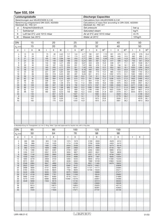
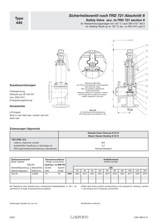
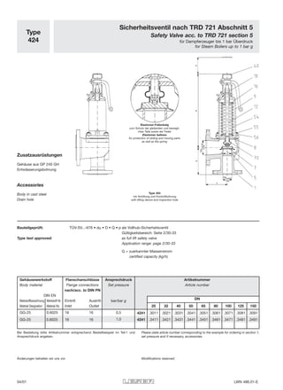
Downloaden Sie, um offline zu lesen
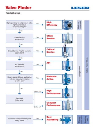


Das Dokument behandelt die verschiedenen Typen von flanged safety relief valves der Serien SBD, TRDF und TRDG, die für spezielle Anwendungen konzipiert sind, einschließlich kritischer und sauberer Dienstleistungen. Es enthält technische Details zu den Ventilen, wie Materialien, Druckstufen, Abmessungen, sowie zusätzliche Komponenten und Zubehör. Außerdem werden Bestellinformationen und genehmigte Prüfnummern bereitgestellt.


