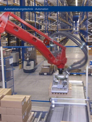
Die Ringfeder Power Transmission GmbH, gegründet 1922 in Krefeld, ist ein globaler Anbieter für Antriebs- und Dämpfungstechnik mit einem Fokus auf innovative Lösungen. Das Unternehmen bietet eine breite Palette von Produkten an, einschließlich metallbalg- und elastomerkupplungen sowie zwischenwellen, und legt Wert auf individuelle Anforderungen der Kunden. Alle technischen Daten sind unverbindlich, und der Nutzer muss sicherstellen, dass die Produkte seinen Anforderungen entsprechen.


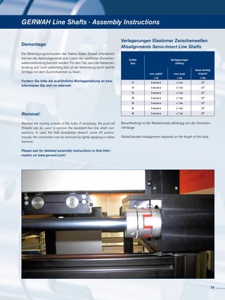
![Technische Hinweise · Metallbalgkupplungen
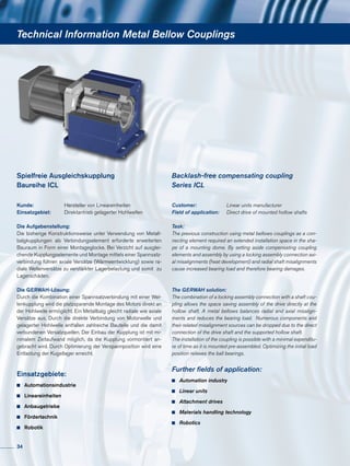
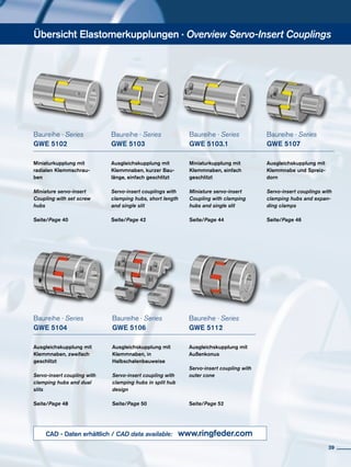
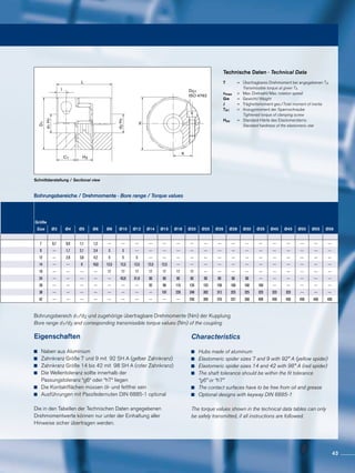
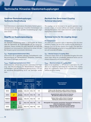
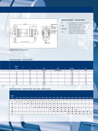
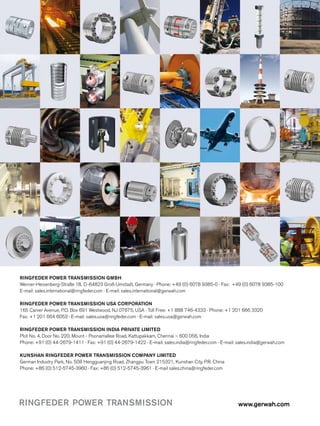
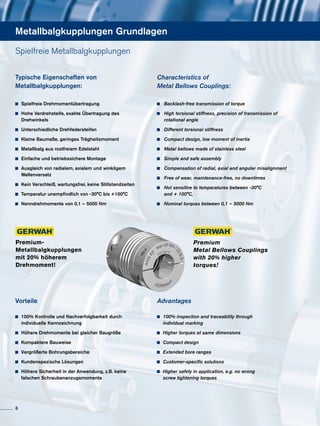
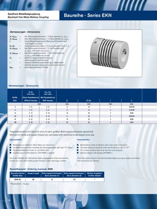
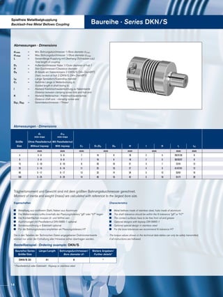
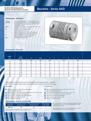
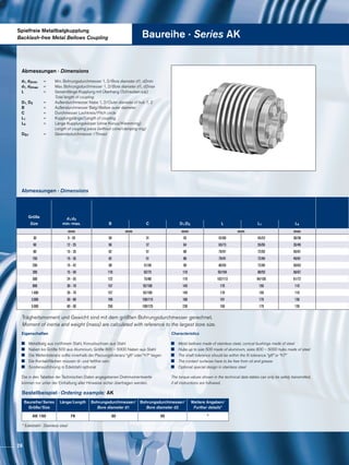
Auslegung/Produktinformation
Spielfreie, drehsteife Metallbalgkupplungen werden einbaufertig
geliefert. Der Metallbalg ist aus rostfreiem Stahl, alle anderen Teile
sind aus Aluminium, bzw. Stahl gefertigt und haben zum Teil eine
umweltfreundliche Konservierung. Die Wellentoleranz sollte inner-
halb der Passungstoleranz “g6“ oder “h7“ liegen. Die Kraftüber-
tragung zwischen Kupplungsnabe und Welle erfolgt durch Pres-
sung und Reibung zwischen den Kontaktflächen. Auf kontrollierten
Anzug der Spannschrauben sowie einwandfreie Beschaffenheit
der Kontaktflächen ist besonders zu achten. Die Kontaktflächen
müssen öl- und fettfrei sein, bei einer Rautiefe von Rtmax. 16 µ für
die Welle. Ausführungen mit Passfedernut sind möglich. Die ange-
gebenen Drehmomente können nur bei Einhaltung aller Hinweise
sicher übertragen werden. Sonst müssen Abstriche gemacht wer-
den.
Auslegung nach dem Drehmoment
Metallbalgkupplungen werden meist nach dem in der Liste der
technischen Daten angegebenen Nenndrehmoment TKN ausge-
legt. Dabei muss das Nenndrehmoment in allen Fällen über dem
regelmäßig zu übertragenden Drehmoment liegen. Dies gilt vor
allem für den Einsatz an Servomotoren, deren Beschleunigungs-
moment in positiver und negativer Richtung um ein Mehrfaches
über dem Nenndrehmoment liegt. Für Metallbalgkupplungen, die
an geregelten, hochdynamischen Antrieben eingesetzt werden, ha-
ben sich folgende Dimensionierungswerte in der Praxis bewährt:
K = 1,5 bei gleichförmiger Bewegung
K = 2 bei ungleichförmiger Bewegung
K = 2,5 – 4 bei stoßender Bewegung
Für Servoantriebe an Werkzeugmaschinen sind Werte für
K = 1,5 – 2 einzusetzen.
Wir führen gerne für Sie die Auslegungsberechnung durch. Nutzen
Sie unsere Kompetenz für Ihren Erfolg. Bitte sprechen Sie uns an!
Auslegung von Metallbalgkupplungen / Berechnungsbeispiel
Servomotor Schlitten
Metallbalgkupplung Kugelrollspindel
TKN ≥ K · TAS ·
JMasch
JMot + JMasch
= [Nm]
30](https://image.slidesharecdn.com/gerwah-metallbalg-de-en20-03-2013c-130715080928-phpapp02/85/Gerwah-metallbalg-de-en-20-03-2013-c-30-320.jpg)
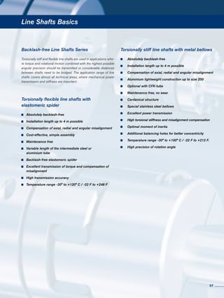
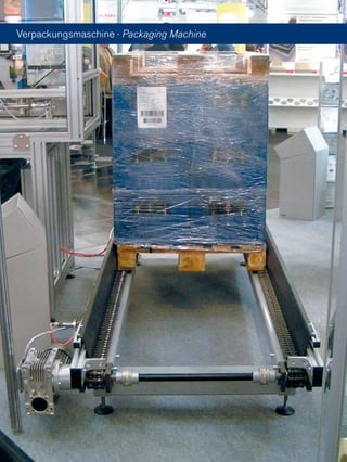
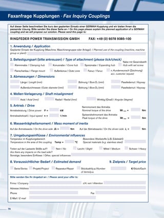
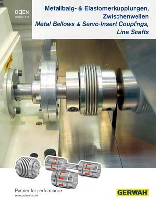
![Technical Information · Metal Bellows Couplings
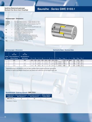
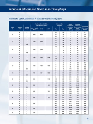
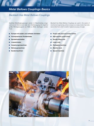
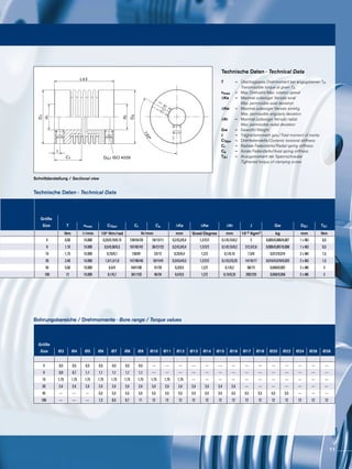
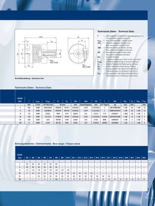
Design / Sample calculation
Design/Product information
Backlash-free, torsionally stiff metal bellows couplings are ready
to install when delivered. The metal bellows are made of stainless
steel, all other parts are made of aluminium or steel and partly have
environmental friendly protective coating. The shaft tolerance should
be within the fit tolerance “g6” or “h7”. The power transmission bet-
ween the coupling hub and the shaft is generated by compression
and friction between the contact surfaces. Special attention must be
paid to the tightening torque of the retaining screws as well as the
perfect condition of the surfaces. The contact surfaces must be free
of oil and grease and have a roughness depth of Rtmax. 16µ for the
shaft. Versions with keyway are available. The torques indicated can
be guaranteed only in compliance with all given advice. Otherwise
cut backs have to be accepted.
Dimensioning in accordance with the torque
Metal Bellows Couplings are generally designed according to the
nominal torque, stated in the list of technical data as TKN. The no-
minal torque must always be higher than the constantly transmit-
ted torque. This generally applies to the use of servo motors, who-
se acceleration moment in both positive and negative directions
exceeds the nominal moment. For the use of Metal Bellows
Couplings which are fitted in controlled, high dynamic drives, the
following dimensioning values have proven to be reliable in practice:
K = 1,5 for evenly shaped movements
K = 2 for unevenly shaped movements
K = 2,5 – 4 for jerky movements
For servo drives within tool making machines, the values for
K= 1,5 – 2 should be used.
We would be pleased to design your metal bellows coupling for you.
Feel free to use our experience and know-how for your success.
Give us a call!
Servo drive Sliding carriage
Metal bellows coupling Ball bearing spindle
TKN ≥ K · TAS ·
JMasch
JMot + JMasch
= [Nm]
31](https://image.slidesharecdn.com/gerwah-metallbalg-de-en20-03-2013c-130715080928-phpapp02/85/Gerwah-metallbalg-de-en-20-03-2013-c-31-320.jpg)
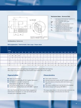
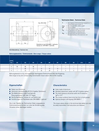
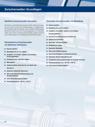
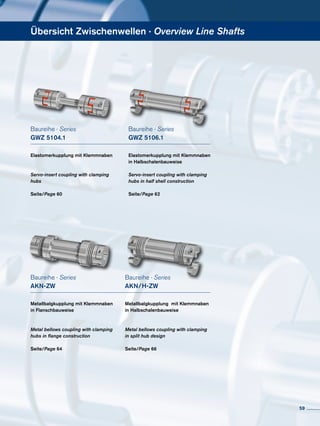
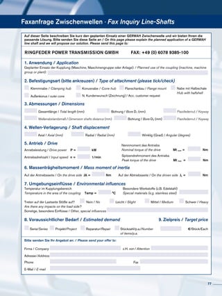
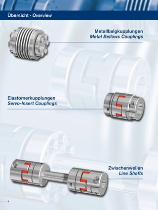
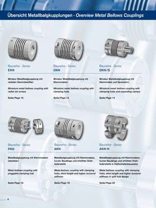
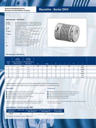
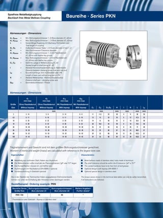
![Antriebsseitig: Servomotor I FT 5104
(Spitzendrehmoment TAS = 160 Nm,
Trägheitsmoment
JMot = 18,3 · 10-3 Kgm2)
Abtriebsseitig: Werkzeugmaschine
(Tragheitsmoment Kugelrollspindel und
Schlitten: JMasch = 17 · 10-3 Kgm2)
Berechnung für den Einsatz einer Metallbalgkupplung an einem Werkzeugmaschinenantrieb
Auslegung nach dem Drehmoment:
Kupplungsauswahl:
AKD 200, TKN = 240 Nm, CTdyn =120 x 103 Nm/rad
Technische Hinweise · Metallbalgkupplungen
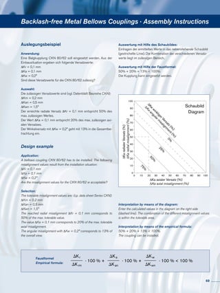
Auslegung nach der Resonanzfrequenz:
Die rechnerisch ermittelte liegt deutlich höher als die zu erwartende Resonanzfrequenz.
Diese liegt bei den meisten gängigen Antrieben, z.B. an NC-Werkzeugmaschinen zwischen 150 und 350 Hz.
Auslegung unter Berücksichtigung der
dynamischen Drehfedersteife
Obwohl Metallbalgkupplungen spielfrei und verdrehsteif sind, darf
nicht übersehen werden, dass sie zwei rotierende Massen verbin-
den. Die Kupplungen können in ungünstigen Fällen wie Torsions-
federn hoher Steifigkeit wirken. Regelschwingungen der Antriebe
und Oberschwingungen im Ankerstrom des Motors dürfen daher
nie im Bereich der mechanischen Resonanzfrequenz liegen. In der
Praxis sollte die Resonanzfrequenz „fres“ um den Faktor 2 größer
Die Metallbalgkupplung ist ausreichend bemessen, da
240 Nm >=154 Nm
sein als die Erregerfrequenz der Antriebe. Die dynamische Dreh-
federsteife CTdyn wurde so gewählt, dass sie in den meisten An-
wendungsfällen nicht im Bereich von Störschwingungen liegen.
Standardmäßig werden verschiedene Drehfedersteifen angeboten.
Wir führen gerne für Sie die Auslegungsberechnung durch. Nutzen
Sie unsere Kompetenz für Ihren Erfolg. Bitte sprechen Sie uns an.
Das geringe Trägheitsmoment der Metallbalgkupplung wird
vernachlässigt. K=Last-, Stoßfaktor gewählt für diesen
Antrieb K = 2 ;
fres =
1
2P
= [Hz]CTdyn ·
JMot + JMasch
JMot · JMasch
TKN ≥ K · TAS ·
JMasch
JMot + JMasch
= 2 · 160 Nm ·
17 · 10-3
Kgm2
(18,3 + 17) · 10-3
Kgm2
= 154 Nm
fres =
1
2P
CTdyn ·
JMot + JMasch
JMot · JMasch
=
1
2P
· 120000 Nm/rad ·
0,0183 + 0,017 Kgm2
0,0183 · 0,017 Kgm2
= 587 Hz
32](https://image.slidesharecdn.com/gerwah-metallbalg-de-en20-03-2013c-130715080928-phpapp02/85/Gerwah-metallbalg-de-en-20-03-2013-c-32-320.jpg)
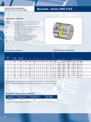
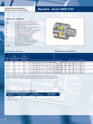
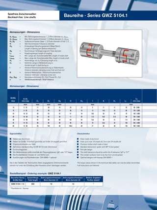
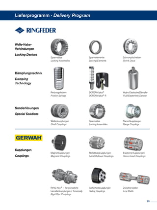
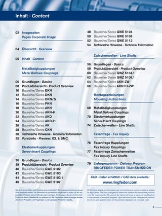
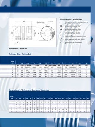
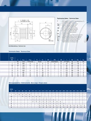
![Technical Information · Metal Bellows Couplings
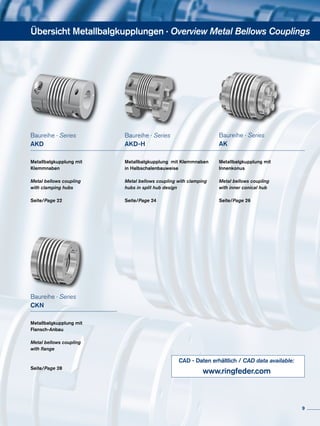
Drive related data for Peak torque TAS = 160 Nm
servo motor/FT 5104: Moment of inertia
JMot = 18,3 · 10-3 Kgm2
Output data for Moment of inertia of ball screw and
machine tool: slide: JMasch = 17 · 10-3 Kgm2
Calculation for the application of a metal bellows coupling in a machine tool drive
Design according to torque:
Coupling selection:
AKD 200, TKN = 240 Nm, CTdyn = 120 x 103 Nm/rad
Design according the resonance frequency:
The arithmetic calculation is clearly higher than the expected resonance frequency.
Usualy for the most established nc-machine tools this value is between 150 to 350 Hz.
Design in consideration of dynamic torsional
stiffness
Although metal bellows couplings are backlash-free and torsion-
rigid, it should not be ignored that they link two rotating masses. In
adverse cases the couplings can act like torsion spring with high
stiffness. The regulating oscillation of the drives and the harmo-
nic oscillation in the armature current of the motor therefore must
never be within the range of the mechanical resonance frequency.
In practise the resonance frequency “fres” must be twice as high as
the excitation frequency of the drive.
The dynamic torsional stiffness CTdyn was selected so that it would
not be within the range of parasitic oscillation of most applications.
Various levels of torsional stiffness are available as standard versi-
ons.
We would be pleased to design your metal bellows couplings
for you. Feel free to use our experience and know-how for your
success. Give us a call !
The low moment of inertia for the metal bellows coupling is
disregared. K = Load factor, impulse factor selected for this
drive K = 2 ;
The metal bellows coupling is dimensioned sufficient,
since 240 Nm > 154 Nm
fres =
1
2P
= [Hz]CTdyn ·
JMot + JMasch
JMot · JMasch
TKN ≥ K · TAS ·
JMasch
JMot + JMasch
= 2 · 160 Nm ·
17 · 10-3
Kgm-2
(18.3 + 17) · 10-3
Kgm-2
= 154 Nm
fres =
1
2P
CTdyn ·
JMot + JMasch
JMot · JMasch
=
1
2P
· 120000 Nm/rad ·
0.0183 + 0.017 Kgm2
0.0183 · 0.017 Kgm2
= 587 Hz
33](https://image.slidesharecdn.com/gerwah-metallbalg-de-en20-03-2013c-130715080928-phpapp02/85/Gerwah-metallbalg-de-en-20-03-2013-c-33-320.jpg)