This document provides an introduction and overview of Corus Advance structural sections for use in steel construction. It includes the following key points:
- Corus is a major UK and global steel producer and manufacturer of structural steel sections.
- Steel construction offers benefits like speed of construction, economy, flexibility, sustainability, and recyclability.
- The document contains selection of structural section property tables from the Corus Advance range to assist students in steel structure design.
- For the full listing of Advance section properties and capacities, the online "Blue Book" can be downloaded from the Corus website.
This document provides formulas and examples for calculating torsional section properties of steel shapes, including the St. Venant torsional constant, warping torsional constant, shear centre location, and monosymmetry constant. It covers open cross sections like W-shapes, channels, angles, and T-sections, as well as closed hollow structural sections that are round or square/rectangular. Simple examples are given to illustrate the calculations.
This document provides guidelines for civil engineering drawing practices in 3 chapters:
1. Structural drawing conventions - Defines scales, views, dimensions, and other structural drawing standards.
2. Drawing components - Details various drawing elements like lines, dimensions, symbols and annotations.
3. CAD drafting - Discusses computer-aided drafting techniques, templates, layers and other digital drafting practices.
The document establishes standards for civil engineering drawings to ensure consistency and clarity across projects. It covers topics like drawing layouts, line weights, dimensioning, modeling and documentation. Adherence to the guidelines will result in structural drawings that effectively communicate engineering design information.
13 beams and frames having nonprismatic membersChhay Teng
1) The document discusses methods for analyzing non-prismatic structural members, such as tapered or stepped beams and frames, using the slope-deflection and moment distribution methods.
2) It describes calculating the deflection of non-prismatic members through integration, and introduces the concepts of stiffness factor K, carry-over factor COF, and the conjugate beam method for analyzing loading properties.
3) An example problem is presented to demonstrate calculating the fixed-end moment FEM at joints A and B of a tapered beam using the given stiffness factors K and carry-over factors COF from the conjugate beam analysis.
This document provides instructions on various AutoCAD commands for 2D drawing and editing, text and hatching, layers, dimensions, blocks, and external references. It consists of 7 chapters that explain tools for drawing lines, circles, arcs, and other objects; editing objects by moving, copying, rotating, mirroring, and arraying; adding text and hatch patterns; managing layers; creating dimensions; inserting blocks; and linking to external drawings. The goal is to teach civil engineering students how to use AutoCAD for 2D drafting.
14. truss analysis using the stiffness methodChhay Teng
1. The document discusses analyzing truss structures using the stiffness method. It begins by introducing the fundamentals of the stiffness method for truss analysis.
2. It describes how to derive the member stiffness matrix for each truss member, which relates the forces and displacements in the member's local coordinate system.
3. It provides equations to transform between the member's local coordinate system and the global coordinate system of the truss, in order to assemble the overall structure stiffness matrix for the truss.
1. The document outlines the chapters in a civil engineering construction work textbook, including introduction to construction, construction materials, construction equipment, and construction management.
2. Chapter 1 discusses construction introduction, which provides an overview of the construction industry and processes. It explains the roles of various construction professionals and their importance in planning and executing construction projects.
3. Chapter 2 covers construction materials used in civil engineering projects, including their properties, uses, and quality control measures.
1. The document discusses using the energy method to calculate deflection in beams, trusses, and frames.
2. The energy method equates the external work done by loads to the internal strain energy stored in the deformed structure.
3. Beams, trusses, and frames can be analyzed by calculating the external work done by forces and moments, and equating it to the strain energy due to bending and twisting. Analytical expressions can then be developed relating the loads to deflections.
12. displacement method of analysis moment distributionChhay Teng
1. The displacement method of analysis, also known as moment distribution, is an iterative technique for analyzing indeterminate structures by redistributing internal moments at joints.
2. Key concepts include member stiffness factors (K), which relate the member end moments (M) to angular displacements (θ), joint stiffness factors (KT), which are the sum of the connected member stiffness factors, and distribution factors (DF), which proportion the influence of each member on a joint based on its stiffness factor.
3. The method involves initially assuming end moments, calculating the distribution factors, and using them to calculate new end moments until the values converge within a specified tolerance. This allows determination of the internal forces throughout the structure.
1. This document discusses tension members and their design strength. Tension members are structural elements that are primarily subjected to tensile forces such as those in trusses, suspension bridges, and cable-stayed bridges.
2. The design strength of a tension member is based on either its gross section resisting yielding, or its net section resisting fracture. Allowable stresses are reduced using strength reduction factors to obtain the design strength.
3. Examples are provided to calculate the design strength of given tension members based on their material properties and dimensions. The effective net area is considered to account for things like bolt holes. Combinations of loads are also checked to ensure the design strength is not exceeded.
1. There are several types of retaining walls, including gravity walls, semi-gravity walls, cantilever retaining walls, counterfort retaining walls, and buttressed retaining walls.
2. Forces acting on retaining walls include active and passive soil pressures. Active pressure is exerted by soil pushing on the front face of the retaining wall, while passive pressure acts on the back side of the wall from soil resistance.
3. The magnitude of active and passive soil pressures depends on factors like the soil type, depth of soil, and angle of internal friction of the soil. Formulas developed by Rankine and Coulomb are commonly used to calculate active and passive pressures.
This document discusses the effective length factor (K) used for calculating the effective length of slender columns. It provides three methods for determining K based on the restraint conditions at the column ends:
1. Using alignment charts and restraint factors (ψA and ψB) for the column and bracing members.
2. Equations relating K to ψmin for partially restrained columns.
3. A simplified equation for K if the column is hinged at one end.
Examples are given to calculate K using the alignment chart method for different bracing conditions. The effective length is important for evaluating the strength and stability of slender columns.
2009 ncdd-csf-technical-manual-vol-i-study-design-guidelinesChhay Teng
This document provides guidelines for the study and design of small-scale infrastructure projects funded by the Commune/Sangkat Fund in Cambodia. It introduces the technical forms and template designs used for roads, irrigation systems, water supply, education, health and sanitation projects. Guidelines are given on how to read and use the template drawings, which conform to the standards of relevant line ministries. The manual aims to support good quality project design and construction supervision that can be implemented with locally available skills and resources. Field visits by technical support officers are recommended to verify project needs and objectives.
The document provides an overview of concrete basics, including the materials used to make concrete, properties of concrete in different states, common concrete tests to measure workability and strength, and factors that affect the strength and durability of hardened concrete. Concrete is made by mixing cement, water, coarse and fine aggregates, and sometimes admixtures, and its workability and strength can be tested using slump and compression tests.
Rebar arrangement and construction carryoutChhay Teng
The document discusses rebar arrangement and construction procedures. It begins by emphasizing the importance of thoroughly understanding construction drawings before beginning work. It then provides details on different types of drawings used for construction, including plans, elevations, sections, and structural drawings. Finally, it discusses rebar characteristics, production processes, and standard symbols and terminology used in construction drawings.
1 dimension and properties table of w shapesChhay Teng
This document provides dimension and properties data for various W-shape steel beams, including their area, depth, web and flange dimensions, elastic properties, plastic modulus, and warping properties. Metrics such as the nominal weight, compact section criteria, moment of inertia, plastic section modulus, and warping constant are given for each beam designation. Over 30 different W-shape beams ranging in size from W1120x4.89 to W910x12.37 are listed with their respective dimension and mechanical properties.
2 dimension and properties table of s shapeChhay Teng
This table provides dimensional and mechanical properties for various S-shape steel beams. It includes properties like cross-sectional area, depth, wall thickness, elastic modulus, plastic modulus, shear center location, and weight. Properties are listed for beam designations ranging from S610x1.77 down to S80x0.08. The data allows comparison of key metrics across different standardized beam sizes.
3 dimension and properties table of hp shapeChhay Teng
This table provides dimensional properties and elastic properties for various HP-shape steel beams. It includes measurements like area, depth, web thickness, flange width and thickness, moment of inertia, plastic modulus, and polar moment of inertia. The data is sourced from an online structural drafting resource and specifies properties for beams with designations like HP360x1.71, HP300x1.23, and HP360x0.53.
4 dimension and properties table c shapeChhay Teng
This document provides dimensional and mechanical properties for various C-shaped cross section profiles. It lists nominal dimensions such as depth, web thickness, flange width and thickness, along with mechanical properties including section area, elastic modulus, plastic modulus, shear center location, polar moment of inertia, and warping constant. C-shapes ranging from 380x0.73mm to 80x0.073mm are specified. Key dimensional and mechanical properties are given to characterize each cross sectional geometry.
6 dimension and properties table of ipe shapeChhay Teng
This document provides dimensional properties for various IPE steel beam shapes. It includes dimensions, cross-sectional area, weight, section properties such as moments of inertia, and minimum dimensions for connections. The table lists data for IPE beams ranging from 80 mm to 600 mm, including their height, width, wall thicknesses, and other geometric properties.
This document provides dimensional properties and specifications for different profiles of IPN-shaped steel beams, ranging from IPN 80 to IPN 600. For each profile, it lists dimensions, cross-sectional area, weight, dimensional properties for detailing, and mechanical properties along the strong and weak axes. A total of 24 IPN profiles are defined in the table with increasing dimensions, areas, and load-bearing capacities from smaller to larger sizes.
8 dimension and properties table of equal leg angleChhay Teng
This document provides dimensional properties and specifications for equal leg angle steel beams of various sizes. It includes dimensions, cross-sectional area, weight, position of axes, surface area, and other mechanical properties. Sizes range from 20x20mm to 120x120mm beams with wall thicknesses of 3mm to 13mm.
The document provides dimensional properties for various UPE-shaped steel beams, including their height, width, wall thickness, flange thickness, area, weight, moments of inertia, and other specifications. Dimensions are given in millimeters and kilograms per meter. Beams range in size from a UPE 80 with a height of 80mm up to a UPE 400 with a height of 400mm.
This document provides dimensional properties for various UPN steel beam shapes. It includes dimensions for the height, width, thicknesses, radii, slopes, cross-sectional areas, weights, and other geometric properties. The table lists these specifications for UPN beams ranging in size from 80x45x6 mm to 400x110x14 mm.
1) This document provides dimensional properties of various U-shape steel beams, including their height, width, wall thicknesses, radii, depth, slope, area, weight, and other geometric properties.
2) Data is provided for 4 different beams: U40 x 20, U50 x 25, U60 x 30, and U65 x 42, with measurements in millimeters and kilograms per meter.
3) The table lists key dimensions, areas, weights, axes, and other properties needed to fully characterize the geometry of each beam.
This document summarizes the key activities undertaken by the Ministry of Land Management, Urban Planning and Construction to establish land use plans and manage land in Cambodia between 1993 and 1997. It outlines the creation of land use plans for Phnom Penh in 1993 and land titling projects targeting two communes in 1993. It also details additional land titling projects, land use planning workshops and training programs conducted during this period. The summary emphasizes the importance of these efforts in formalizing land management and establishing the legal framework for land administration in Cambodia.
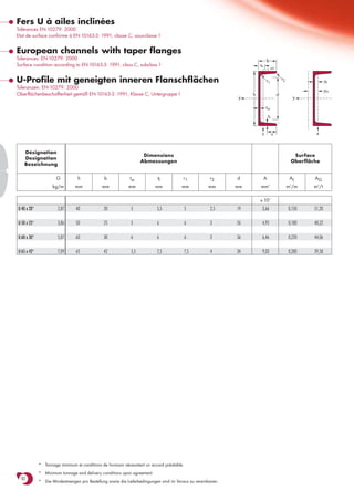
1. Fers U à ailes inclinées
Tolérances EN 10279: 2000
Etat de surface conforme à EN 10163-3: 1991, classe C, sous-classe 1
European channels with taper flanges
Tolerances: EN 10279: 2000 b
Surface condition according to EN 10163-3: 1991, class C, subclass 1 ss
45o
U-Profile mit geneigten inneren Flanschflächen r1 r2 ys
Toleranzen: EN 10279: 2000
ym
Oberflächenbeschaffenheit gemäß EN 10163-3: 1991, Klasse C, Untergruppe 1 h d
y y
tw
tf
z u z
Désignation
Dimensions Surface
Designation
Abmessungen Oberfläche
Bezeichnung
G h b tw tf r1 r2 d A AL AG
kg/m mm mm mm mm mm mm mm mm 2
m /m
2
m2/t
x 102
U 40 x 20* 2,87 40 20 5 5,5 5 2,5 19 3,66 0,150 51,20
U 50 x 25* 3,86 50 25 5 6 6 3 26 4,92 0,180 48,22
U 60 x 30* 5,07 60 30 6 6 6 3 36 6,46 0,220 44,06
U 65 x 42* 7,09 65 42 5,5 7,5 7,5 4 34 9,03 0,280 39,58
* Tonnage minimum et conditions de livraison nécessitent un accord préalable.
* Minimum tonnage and delivery conditions upon agreement.
82
* Die Mindestmengen pro Bestellung sowie die Lieferbedingungen sind im Voraus zu vereinbaren.
2. Notations pages 211-215 / Bezeichnungen Seiten 211-215
Valeurs statiques / Section properties / Statische Kennwerte Classification
U
Désignation
EN 10113-3:1993
EN 10025:1993
EN 10225:2001
axe fort y-y axe faible z-z ENV 1993-1-1
Designation
Bezeichnung strong axis y-y weak axis z-z pure pure
starke Achse y-y schwache Achse z-z bending y-y compression
G Iy Wel.y Wpl.y■ iy Avz Iz Wel.z Wpl.z’ iz ss It Iw ys ym
S 235
S 355
S 235
S 355
4 3 3 2 4 3 3 4 6
kg/m mm mm mm mm mm mm mm mm mm mm mm mm mm mm
x 104 x 103 x 103 x 10 x 102 x 104 x 103 x 103 x 10 x 104 x 109 x 10 x 10
U 40 x 20 2,87 7,62 3,81 4,91 1,44 1,96 1,15 0,86 1,65 0,56 13,4 0,39 0,003 0,67 1,03 1 1 1 1 ✔
U 50 x 25 3,86 16,9 6,76 8,52 1,85 2,52 2,50 1,48 2,84 0,71 14,6 0,59 0,009 0,81 1,36 1 1 1 1 ✔
U 60 x 30 5,07 31,7 10,56 13,3 2,21 3,54 4,53 2,16 4,19 0,84 15,8 0,89 0,024 0,90 1,52 1 1 1 1 ✔
U 65 x 42 7,09 57,7 17,77 21,7 2,53 3,68 14,1 5,06 9,38 1,25 18,0 1,61 0,082 1,39 2,58 1 1 1 1 ✔
■ Wpl.y est calculé selon l’hypothèse d’un diagramme de contraintes bi-rectangulaire et n’est applicable que si deux ou plusieurs fers U sont associés de façon
à constituer une section doublement symétrique pour laquelle un moment de flexion agissant dans le plan du centre de gravité n’engendre pas de torsion.
■ Wpl.y is determined assuming a bi-rectangular stress block distribution. Thus, the given value applies only if two or more channels are combined in such
a way to form a doubly symmetric cross-section so that the bending moment acting in the plane of the centre of gravity will not lead to torsion.
■ Für die Berechnung von Wpl.y wurde eine doppelrechteckige Spannungsverteilung angenommen. Der angegebene Wert ist daher nur anwendbar,
wenn zwei oder mehr U-Profile so miteinander kombiniert sind, dass sie einen doppelsymmetrischen Querschnitt bilden, womit ein Biegemoment, das in
83
der Schwerpunktebene angreift, keine Torsion hervorruft.