12-mal heruntergeladen
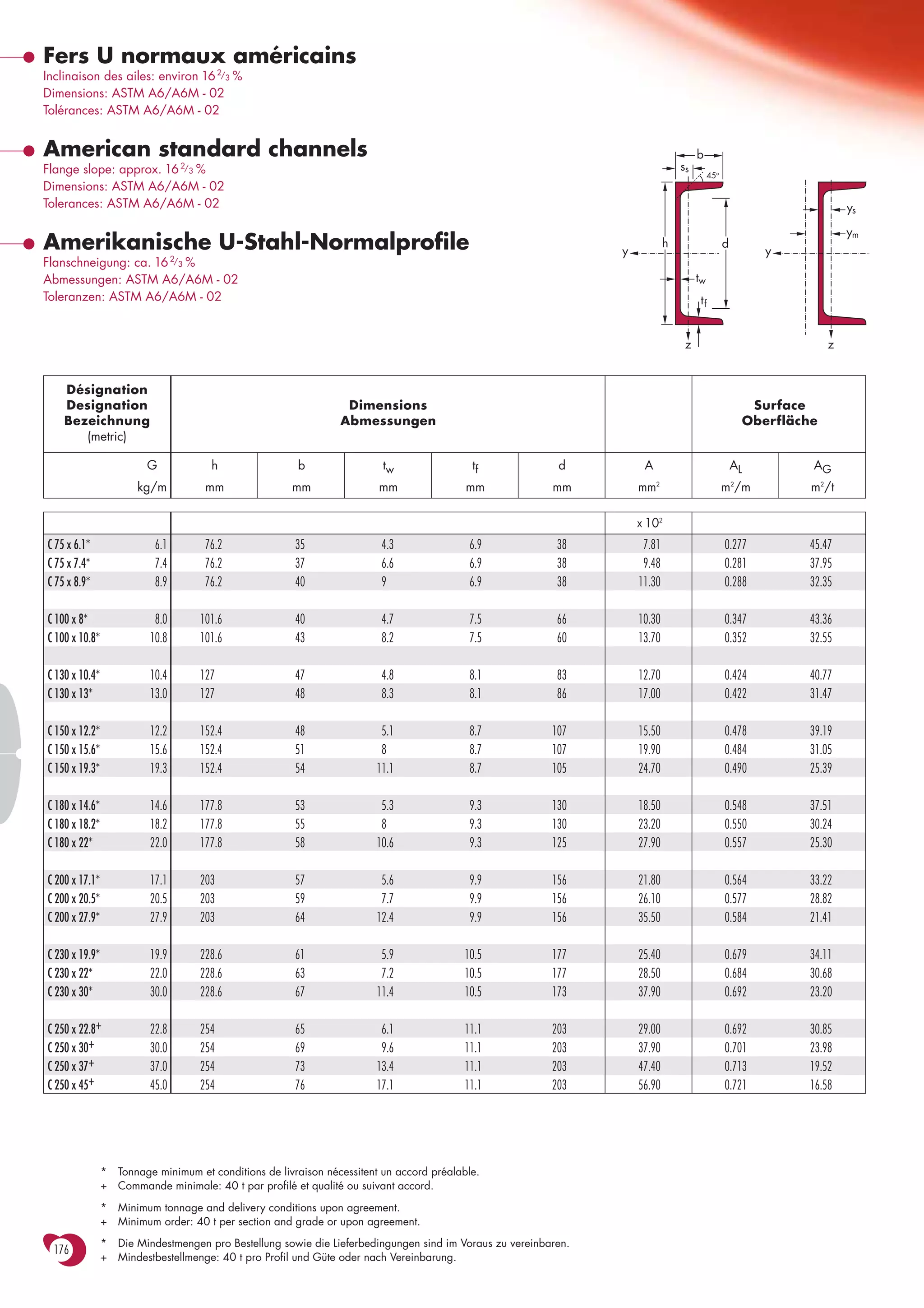
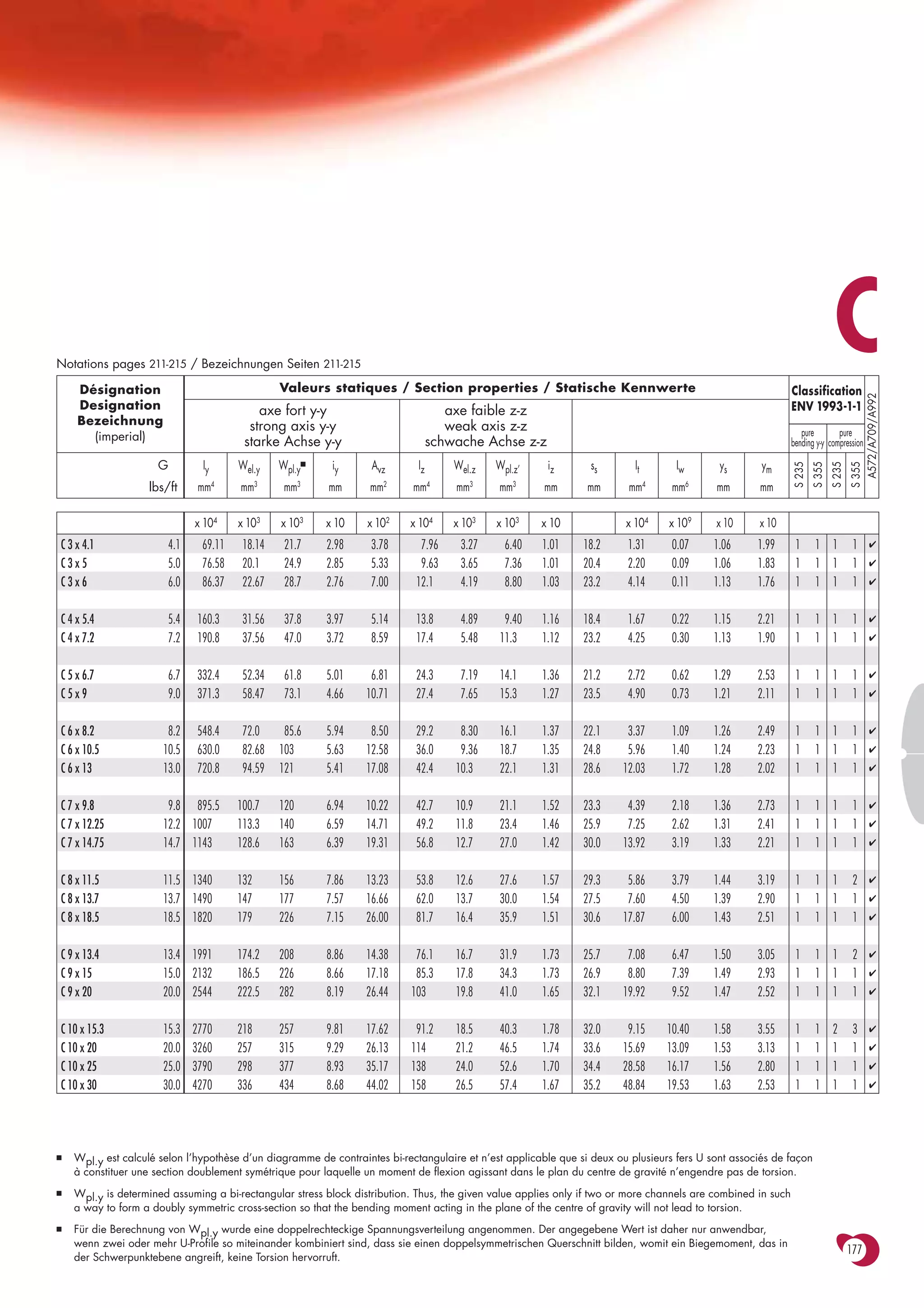
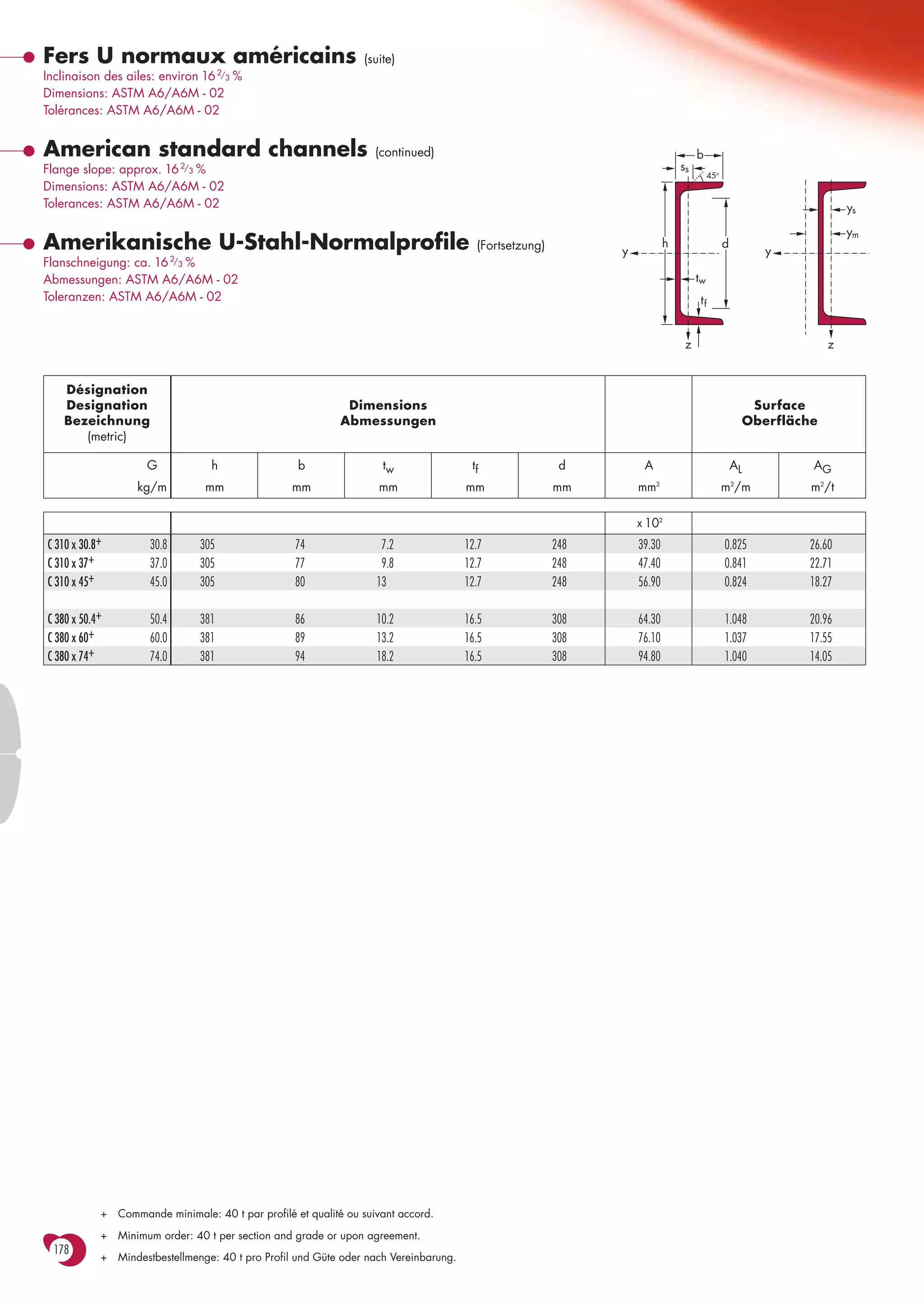
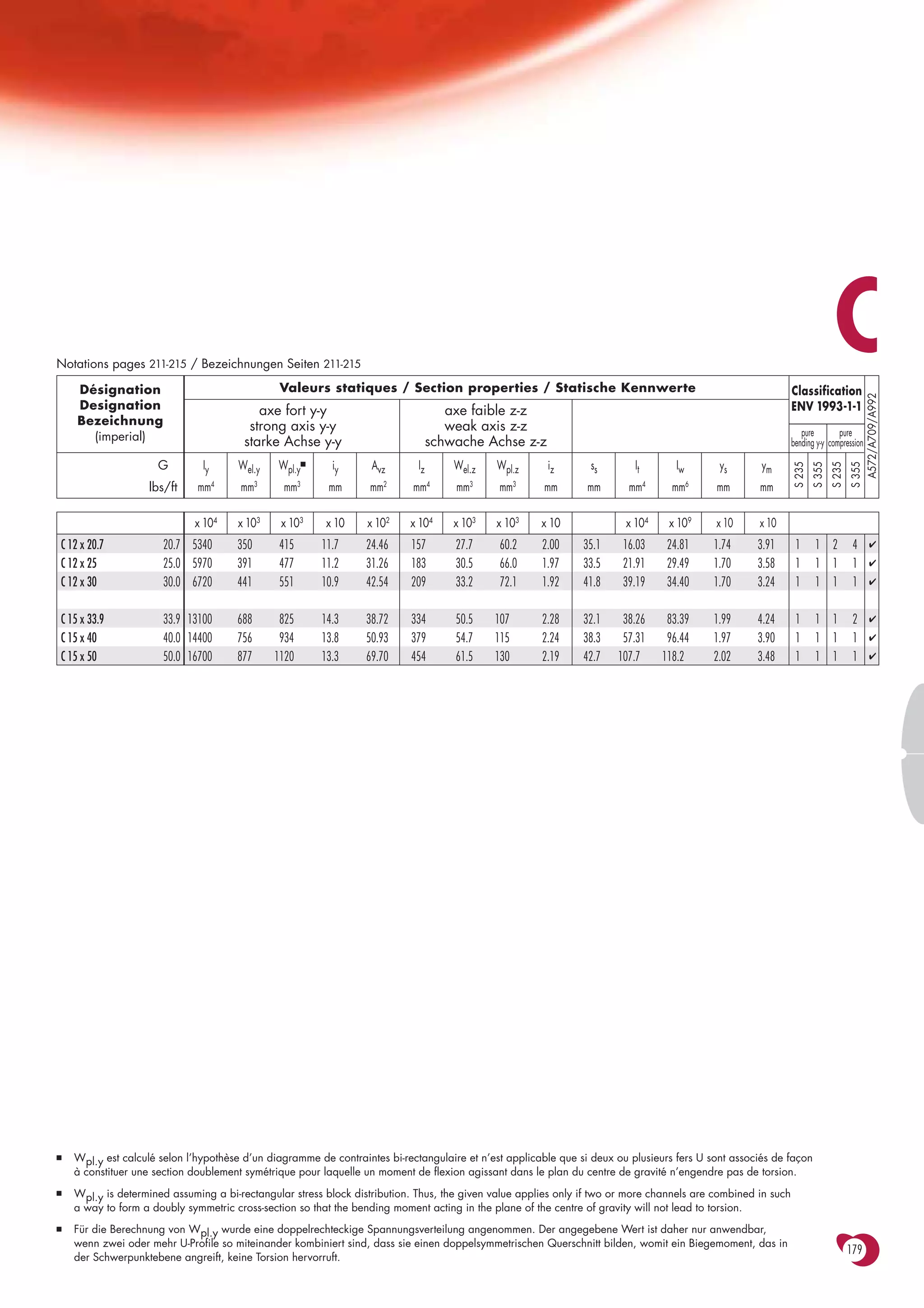

Das Dokument enthält technische Spezifikationen und Abmessungen für amerikanische U-Stahl-Profile gemäß den Normen ASTM A6/A6M-02, einschließlich Flanschneigungen und Toleranzen. Es listet verschiedene Profilgrößen, Gewichte und geometrische Eigenschaften auf und weist auf Mindestbestellmengen und Lieferbedingungen hin. Zudem werden Informationen zu Biegemomenten und deren Berechnung für bestimmte Profile bereitgestellt.


