Ijsetr vol-4-issue-10-3618-3623
•
0 gefällt mir•41 views

hydrodynamic study of four duct swirling combustion chamber

Empfohlen
Empfohlen
Weitere ähnliche Inhalte
Was ist angesagt?
Was ist angesagt? (17)
Ähnlich wie Ijsetr vol-4-issue-10-3618-3623
Ähnlich wie Ijsetr vol-4-issue-10-3618-3623 (20)
Kürzlich hochgeladen
Kürzlich hochgeladen (20)
Ijsetr vol-4-issue-10-3618-3623
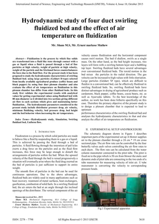
- 1. International Journal of Science, Engineering and Technology Research (IJSETR), Volume 4, Issue 10, October 2015 ISSN: 2278 – 7798 All Rights Reserved © 2015 IJSETR 3618 Abstract— Fluidization is the process by which fine solids are transformed into a fluid like state through contact with a gas or liquid when a fluid is passed through a bed of fine particles at high velocity, weight of particle at high velocity, weight of the particle and the frictional forces counterbalances the force due to the fluid flow. For the present study it has been proposed to study the hydrodynamic characteristics of swirling fluidized bed. using large particles (Geldart D-type) selected from locally available agricultural produce (coffee beans and black pepper) by using four duct plenum chamber and also evaluate the effect of air temperature on fluidization in this plenum chamber has differ from other fluidized beds. In this study first validate the experimental results with analytical values for getting experimental values using fluidized bed with 80 mm diameter so it divided into two sections giving different air flow to each sections which gives and maintaining better fluidization. . The hydrodynamic parameters considered in the present study include distributor pressure drop, air velocity, minimum fluidizing velocity, bed pressure drop, bed height and the bed behavior when increasing the air temperature. Index Terms—Hydrodynamic study, Simulation, Swirling fluidized bed, Uniform flow. I. INTRODUCTION Fluidization is a process by which solid particles are made to behave like a fluid by suspending them in a gas or a liquid. This is achieved by passing the fluid through a bed of particles. A fluid flowing through the interstices of pal1icles exerts a drag force on the particles and as the fluid flow increases, this force may be large enough to disturb the arrangements of particles within the bed. When the upward velocity of the fluid through the bed is raised progressively a situation will eventuallyarise where the fluid drag exerted on the bed of particles is just sufficient to support its entire weight. The smooth flow of particles in the bed can be used for continuous operations. Due to the above advantages, fluidized beds are widely used in many applications such as heat recovery. treatment of metal surfaces, heat exchangers, gasification, combustion of solid fuels. In a swirling fluidized bed, the air enters the bed at an angle through the inclined openings of the distributor. The vertical component of the air Manuscript received Oct , 2015. Shans M.S, Mechanical Engineering, M.A College of Engg Kothamangalam,., Ernakulam (Kerala), India, Mobile No: 9633392814 Ernest Markose Mathew, Faculty of Mechanical Engineering, M.A College of Engg., Ernakulam (Kerala), India, Mobile No.9846121355, velocity causes fluidization and the horizontal component causes swirl motion. The bed if shallow, swirls as a single mass. On the other hand, as the bed height increases, two layers will form with a swirling bottom layer and a bubbling top layer. Swirling fluidized beds have several advantages over conventional fluidized beds. The toroid motion in the bed mixes the particles in the radial direction. The gas velocitycan be increased to high values with little elutriation. Large particles (Geldart 'D' type), which are difficult to fluidize in a conventional bed, can be effectively fluidized in swirling fluidized beds. So, swirling fluidized beds have distinct advantages in drying of agricultural produce such as cardamom, black pepper, coffee beans, cocoa beans, etc. as well as Ayurvedic tablets. To the best knowledge of the author, no work has been done hitherto specifically on this case. Therefore the primary objective of the present study is to design a plenum chamber that is expected to lead to optimum performance characteristics of the swirling fluidized bed and analyses the hydrodynamic characteristics in that and also analyze the effect of air temperature on fluidization. II. EXPERIMENTAL SETUP AND PROCEDURE The schematic diagram shown in Figure 1 describes important parts of the experimental set-up A blower supplies air to the plenum chamber through a 24 cm * 19 cm cross sectional pipe. The air flow rate can be controlled by the four butterfly valves each valves controlling the air flow rates to each ducts . The flow rate can be calculated from the water column manometer connected to the pitot tube. The pitot is fixed on to the pipe which is 50 cm from blower the static and dynamic ends of pitot tube are connecting to the two ends of u tube manometer for measuring velocity of inlet air. U tube manometer is converting the velocity to corresponding pressure heads. Fig.1 Experimental apparatus Hydrodynamic study of four duct swirling fluidized bed and the effect of air temperature on fluidization Mr. Shans M.S, Mr. Ernest markose Mathew
- 2. International Journal of Science, Engineering and Technology Research (IJSETR), Volume 4, Issue 10, October 2015 ISSN: 2278 – 7798 All Rights Reserved © 2015 3619 A pointer attached to a rack and pinion arrangement helps to measure the readings on the manometer without parallax error. The entry of air in to the plenum chamber is made tangential to it so as to have a clockwise air circulation within this chamber. This is to reduce the pressure loss at entry in the distributor, as the inclined vane hole type distributors were also designed to have a clockwise air entry into the bed. The bed pressure drop can be obtained by connecting the pressure tapings from the bed to the positive terminal of the digital micro manometer (FCO 520 air pro) and leaving the negative terminal open to the atmosphere. A. Device description The main part of all fluidized beds are the plenums here four duct plenum chamber made for the study. This is special type of plenum that provides better swirling action on top of the distributor plate. Which divide the plenum by three zones the centre portion has no airflow outer two zones gives equal amount of air from inlets the plenum has 800 mm diameter and three zones are 600 mm, 400 mm respectively the height is 600 mm. The distributor plate is provided on the top of plenum the role of the distributor is to evenly distribute the fluidization gas across the bed inlet and hence to initiate effective gas-solids contacting. Inclined vanes are provided for getting swirling on the top of distributor. Design features of distributor on the table 1 Table.I description of distributor Sl no. Particulars 1 Minimum gap between slits (mm) 10 2 Length of the slit (mm) 25 3 Width of the slit (mm) 1.8 4 Area of opening of each slit 43.2 5 Total number of slits 1024 6 Total area of opening (mm'') 53913.6 7 Percentage area of opening 14.30 8 Percentage useful area of distributor 75 B. Particle description Gerald D type particles like coffee bean and peeper are used for the studythe special features of these types of particles are heavy mass compared to other particles using for the experiment properties are shown in Table 2 III. NUMERICAL SETUP AND VALIDATION CFD is a sophisticated computationally-based design and analysis technique. CFD software gives you the power to simulate flows of gases and liquids, heat and mass transfer, moving bodies, multiphase physics, chemical reaction, fluid-structure interaction and acoustics through computer modeling. CFD is one of the branches of fluid mechanics that uses numerical methods and algorithm to solve and analyze problems that involve fluid flows and also simulate the flow over a piping, vehicle or machinery etc. Computers are used to perform millions of calculations required to simulate the interaction of fluids and gases with the complex surfaces used in engineering. The models of the four duct and the six duct plenum chambers were generated using Solidworks Premium 2014. Figure shows the created model of fluidized bed chamber all dimensions are same as that of experimental set up. Total height of 1200 mm and the diameter 800 mm and tangential air entry provided with four duct, plenum chamber divided into 3 sections and giving airflow passage to the outer two sections shown in figure 2. Table II Particle description Sl no. Property Coffee beans pepper 1 Average Particle diameter (mm) 8.78 4.38 2 Average Particle density (kg/m3) 760 1200 3 Bed density (kg/m3) 470 600 4 Bed Voidage (%) 39 50 A. Governing Equations For the simulation purpose, the following 3-D equations in cylindrical coordinate form have been solved numerically for a Newtonian, incompressible fluid: Continuity equation 0 i i x U Dt D (1) Momentum equation j i ij ji j i j g xx P x U U t U (2) k k ij j i i j ij x U x U x U 3 2 (3) Energy equation i j ij ii i i i x U x T x U P x T Uc t T c 2 2 (4) Fig 2. Numerical model
- 3. International Journal of Science, Engineering and Technology Research (IJSETR), Volume 4, Issue 10, October 2015 ISSN: 2278 – 7798 All Rights Reserved © 2015 IJSETR 3620 B. Meshing and Boundary condition The grids are generated using FLUENT. The basic principle in meshing is that it should have finer elements to get better accuracy of the result. At the same time, number of grids should not exceed available computational capacity. The geometry imported to ANSYS work bench15 it is not necessary to get a converged solution with a particular mesh element or using fine meshes so mesh quality need to be checked. The aspect ratio is 3.4 (up to 40 aspect able) and Orthogonal quality is 0.78 (range from 0 to 1, near to 1 is good) Tetra mesh is used for getting better result and lowering converging time the whole geometry has total 3.6 million cells. The meshing model then transferring to solver section where the boundary conditions are applied. The standard k-epsilon model was used to calculate the turbulent viscosity this model allows for a more accurate near wall treatment. The operating pressure was taken as default 101325 Pa, since all the experimental measurements are taken at gauge pressure. Operating Inlet velocities are varies from 3 to 8 m/s for measuring corresponding pressure on the top of the distributor and the bed pressure drops along radial distance. Outlet condition taken as zero gauge pressure and the fluid medium taken as air and convergent criteria is 0.0001. IV. RESULTS AND DISCUSSIONS At first the analysis started with 2 million of cells then got total pressure of 101388 pa at 5 mm above distributor then repeating the analysis with increasing number of elements by 3.2 to 4.4 million total pressure also increases. The number of cells beyond 4.4 million the total pressure changes become negligible as shown in figure 3 almost constant pressure obtained when increasing cell number 5 to 7.7 million so easy to fix the number of cells. After completing this study number of elements taken as 4.4 million because beyond that no effect on total pressure which also reducing the iteration time. Vortices are created on the top of distributor because of the sudden pressure drop from plenum chamber to distributor greater pressure accumulated in bottom of distributor and a uniform pressure distribution obtained on distributor as shown in figure 4. Fig.3 Grid independent study The figure5 shows variation average value of total pressure above the distributor with the inlet velocities. The values taken from different points along the radial direction on the distributor, Pressure first increases with increase in velocity then it became constant and decreases with increases in velocity. Some variation obtained in experimental and the analytical values because of some errors obtained during the experiment. Fig.4 Pressure on the top of distributor From the figure5 the cut in velocity is constant that is 4m/s then the pressure constant in between 4 to 5 m/s velocities. Fig.5 validation of experimental and analytical results (avg of results from points 210,240,300,330,360mm from centre of distributor) A. Hydrodynamic parameters Distributor pressure drop is an important parameter, which influences the energy consumption and the fluidization quality. In general, a higher distributor pressure drop leads to higher energy consumption. It has been reported that a minimum distributor pressure drop as high as 350 mm of water is required for a uniform fluidization in a shallow conventional bed. In here using 7 raw 150 vane angle distributor so that the percentage of area opening increases but it is sufficient for getting optimum pressure drop,300 mm of water pressure drop obtained from the experiment. Fig.6 Bed pressure drop obtained on 10 mm above the distributor (coffee beans)
- 4. International Journal of Science, Engineering and Technology Research (IJSETR), Volume 4, Issue 10, October 2015 ISSN: 2278 – 7798 All Rights Reserved © 2015 3621 The variation of bed pressure drop along the radial direction in the case of seven row vane type distributors has been studied using two bed materials (coffee beans and pepper) shown in figure6. It can be said that, the bed pressure drop increases with an increase in the superficial velocity up to the minimum fluidizing velocity. Beyond the minimum fluidizing velocity and up to the beginning of the swirl motion, there is no significant variation in the bed pressure drop with an increase in the superficial velocity. It is to be noted that, while the bed pressure drop increases with velocity in the outer region of the bed, it decreases in the inner region. Some variation of graph obtained on figure 6 and 7 because of voidity is higher for pepper and lower for coffee bean and also lower mass of pepper. Review Stage Submit your manuscript electronically for review. B. Final Stage When you submit your final version, after your paper has been accepted, prepare it in two-column format, including figures and tables. C. Figures Fig.6 Bed pressure drop obtained on 10 mm above the distributor (pepper) In inclined hole/vane type distributor air will swirl in the bed. Because of this swirling, at any point in a plane parallel to the distributor, the air will have radial and tangential components of velocity. Fig.7 Variation of radial and tangential velocity v /s flow rate at 240 mm from centre Fig.8 Variation of radial and tangential velocity v /s flow rate at 280 mm from centre Fig.9 Variation of radial and tangential velocity v /s flow rate at 360 mm from centre The radial component contributes to the radial mixing of the particles, tangential component leads to swirl motion. In a given plane, measurements were taken at different radial distances at an interval of 240 mm from 280 mm to 380 mm. It is to be noted that at radial distances 180 mm the air flow was not significant and hence measurements were not taken for the values of radial distances lower than 240 mm. The tangential component of velocity is seen to be higher at a radial distance of 360 mm for all flow rates compared to the radial component. As the radial distance reduces, the difference between the tangential component and radial component of the velocity reduces. For a radial distance of 210 mm and lover, the radial component of velocity is higher than the tangential component radial mixing of the particles are higher at the centre portion and comparatively low at the outer portions. B. Effect of air temperature As the temperature of the bed changes, the obvious changes are in the properties of the fluidizing medium. When gas is used for fluidizing, its density decreases with increase in temperature, while its viscosityincreases. At low Reynolds number, viscous effects predominate. The vortices are increasing while increases the temperature as shown in figure 10 so that greater mixing and fluidization obtained this leads to decrease the minimum fluidizing velocity. Localized swirling increases as temp increases Fig.10 Streamlines of vortices [temp 350k]
- 5. International Journal of Science, Engineering and Technology Research (IJSETR), Volume 4, Issue 10, October 2015 ISSN: 2278 – 7798 All Rights Reserved © 2015 IJSETR 3622 The pressure obtained on the top of the distributor get decreasing when the temperature increases from the graph we have to conclude that when the temperature increases the pressure drop decreases and also the minimum fluidization velocity also decreases. Fig.11 Variation of pressure v/s velocity graph in different temperatures At first from the graph when temperature is 300k the particle starts fluidized on the velocity 4.1 m/s then the fluidization continuous to the velocity of 5 m/s beyond that didn’t get proper fluidization. Then the temperature of inlet air increases to 350k the particles starts fluidization on 3.7 m/s but the maximum pressure obtained decreases and also we get wide range of fluidization region to 5 m/s velocity. After increasing the temperature beyond 350k then the pressure drop decreases gradually so that the minimum fluidizing velocity decreases and the fluidizing region increases. Fig.12 pressure variation 10 cm above distributor V. CONCLUSION The experiment conducted by using four duct plenum chamber which is differ from ordinary plenum chambers by using four duct plenums better fluidization obtained on the bed. The voracity and other parameters are measured by conducted a cfd analysis on this plenums. For getting the better results the model made by using solid works 2015 then imported to ansys 15 for the cfd works. First validate the experiment and cfd results and get small variation in the results and the plotting graphs that is because of some resistance offered by the actual model so we don’t get the pressure on some velocities. I conducted the experiment by using 5 different velocities 3 to 8 m/s and get fluidization on intermediate velocities that time get almost constant pressure on the bed. The gelard D type particles are using for the experiment then the hydrodynamic properties are obtained from that the pressure drop on the distributor increases with increase in the particle densitywe get high pressure drop on coffee bean than pepper. But the minimum fluidizing velocity decreases when the density increases the pepper get fluidized in lower velocity than coffee beens. • The vortices creating above the distributor increases with increases in temperature • The temperature increases the pressure obtained on bed decreases • Minimum fluidizing velocity increases with increase in temperature • Fluidizing region increases with increase in temperature So have to conclude that the temperature 350k gives better results than all other temperature we get lower fluidizing velocity and wide range of fluidization in moderate pressure ACKNOWLEDGMENT The authors would like to thank all the faculties of mechanical engineering department for their valuable support to the research work REFERENCES [1] Agarwal J. c., Davis W. L., and King D. T., (1962), Fluidized -bed Coal dryer, Chemical Engil/eering Progress, Vo1.58 [2] Binod Srccnivasan and Vijay R. Raghavan, (2002), Hydrodynamics or a swirling fluidized bed, ('hemical £i7gineering and Processing. VolA [3] Birk R. H., Camp G. A. and Hutchinson L. B., (1990). Design or an Agglomeration Resistant Gas Distributor. AIChE Symposium series. Vol 86. PP 16-21. [4] Botterill .f. S. M., Tcoman Y. and Yiiregir K. R., (1982). The Effect or Operating temperature on the Velocity of Minimum Fluidization. Bed Voidage and General Behavior. Powder Technology, Vol.3l, pp 101-110. [5] 4] M. Ozbey, M.S. Soylemez, effect of swirling flow on fluidized bed drying of wheat grains, Energy Conversion & Management, 46 (2005) 1495-1512. [6] E. Peirano, V. Delloume, F. Johnsson, B. Leckner and O. Simonin, Numerical simulation of the fluid dynamics of a freely bubbling fluidized bed: influence of the air supply system, Powder Technol. 122 (1) (2002) 69-82. [7] F. Johnsson, G. Larsson and B, Leckner, Pressure and flow fluctuations in a fluidized bedinteraction with the air-feed system, Chem. Eng. Sci. 57 (8) (2002) 1379-1392. [8] S., Johnsson, F., Leckner, B. (2004). Interaction between a fluidized bed and its air-supply system: Some observations. Industrial and Engineering Chemistry Research, 43, 5730–5737. [9] S., Leckner, B., Johnsson, F. (2007). Characterization of fluid dynamics of fluidized beds by analysis of pressure fluctuations. Progress in Energy and Combustion Science, 33, 453–496. [10] H., Geldart, D. (1997). The response time of pressure probes. Powder Technology, 90, 149–151.
- 6. International Journal of Science, Engineering and Technology Research (IJSETR), Volume 4, Issue 10, October 2015 ISSN: 2278 – 7798 All Rights Reserved © 2015 3623 First Author Name: Shans M.S Qualification: B.tech degree in mechanical engineering Current status: Doing M.tech specialized in thermal power engineering College: Mar Athanasius College of Engineering kothamangalam Place: Ernakulam, Kerala, India Mobile:+919633392814 This is my first research work, No publications yet Second Author Name: Ernest Markose Mathew Qualification: M.Tech Current Status: Associate professor in mechanical engineering department and Doing research work (phd) College: Mar Athanasius College of Engineering kothamangalam Place: Ernakulam, Kerala, India Mobile:+919846121355