Weitere ähnliche Inhalte
Ähnlich wie EASYVEEP (20)
Mehr von SANTIAGO PABLO ALBERTO
Mehr von SANTIAGO PABLO ALBERTO (20)
EASYVEEP
- 2. Order No.: 670763
Description: MONTAGEANLEIT.
Designation: D:EASY-VEEP-TW-DE/GB
Edition: 02/2003
Author: Ulrich Karras
Graphics: Doris Schwarzenberger
Layout: 27.02.2003, Beatrice Huber, Anita Nrecaj
© Festo Didactic GmbH & Co. KG, 73770 Denkendorf, Germany, 2003
Internet: www.festo.com/didactic
e-mail: did@festo.com
Weitergabe sowie Vervielfältigung dieses Dokuments, Verwertung und
Mitteilung seines Inhalts verboten, soweit nicht ausdrücklich gestattet.
Zuwiderhandlungen verpflichten zu Schadenersatz. Alle Rechte
vorbehalten, insbesondere das Recht, Patent-, Gebrauchsmuster- oder
Geschmacksmusteranmeldungen durchzuführen.
The copying, distribution and utilization of this document as well as the
communication of its contents to others without expressed
authorization is prohibited. Offenders will be held liable for the payment
of damages. All rights reserved, in particular the right to carry out
patent, utility model or ornamental design registration.
- 3. Inhalt
Contents
© Festo Didactic GmbH & Co. KG • EasyVeep 3
1. Einleitung__________________________________________ 5
1.1 Dieses Handbuch ____________________________________ 5
1.2 Das Konzept EasyVeep________________________________ 5
2. Inbetriebnahme _____________________________________ 7
2.1 Gerätesatz von EasyVeep______________________________ 7
2.2 Das Prozessinterface EasyPort _________________________ 7
2.3 Softwareinstallation_________________________________ 15
3. Menüs____________________________________________ 24
3.1 Konfiguration der Kommunikationsschnittstelle __________ 24
3.2 Beispielsmodelle ___________________________________ 24
3.3 Verbindung ________________________________________ 25
3.4 Manueller Betriebsmodus ____________________________ 26
3.5 Emulation _________________________________________ 27
3.6 Funktions-/Inbetriebnahmetest _______________________ 28
4. Training mit EasyVeep ______________________________ 29
4.1 Warmwasserbehälter ________________________________ 29
4.2 Drei Zylinder _______________________________________ 30
4.3 Fahrstuhl__________________________________________ 31
4.4 Waschmaschine ____________________________________ 32
4.5 7-Segmentanzeige __________________________________ 34
4.6 Weinabfüllung _____________________________________ 35
4.7 Kugel-Sortieranlage _________________________________ 37
4.8 Bahnübergang mit Schranke __________________________ 38
4.9 Windgenerator _____________________________________ 39
4.10 Tonbandgerät ______________________________________ 41
4.11 Schatzsuche _______________________________________ 42
4.12 Gewächshaus ______________________________________ 44
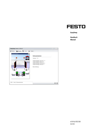
4.13 Schleusenkammer __________________________________ 46
4.14 Parkhaus__________________________________________ 48
4.15 Modell Lampe______________________________________ 49
4.16 Modell Zylinder_____________________________________ 50
Deutsch
- 4. Inhalt
Contents
4 © Festo Didactic GmbH & Co. KG • EasyVeep
1. Introduction _______________________________________ 51
1.1 This Manual _______________________________________ 51
1.2 The EasyVeep concept _______________________________ 51
2. Commissioning ____________________________________ 53
2.1 EasyVeep equipment set _____________________________ 53
2.2 The EasyPort process interface ________________________ 53
2.3 Software installation ________________________________ 61
3. Menus____________________________________________ 70
3.1 Configuring the communication port____________________ 70
3.2 Example models ____________________________________ 70
3.3 Connection ________________________________________ 71
3.4 Manual operating mode______________________________ 72
3.5 Emulation _________________________________________ 73
3.6 Function test/commissioning test______________________ 74
4. Training with EasyVeep______________________________ 75
4.1 Hot water tank _____________________________________ 75
4.2 Three cylinders _____________________________________ 76
4.3 Lift _______________________________________________ 77
4.4 Washing machine ___________________________________ 78
4.5 7-segment display __________________________________ 80
4.6 Bottling wine_______________________________________ 81
4.7 Ball sorting system__________________________________ 83
4.8 Level crossing with barrier____________________________ 84
4.9 Wind generator_____________________________________ 85
4.10 Tape recorder ______________________________________ 87
4.11 Treasure hunt ______________________________________ 88
4.12 Greenhouse _______________________________________ 90
4.13 Lock chamber ______________________________________ 92
4.14 Multi-storey car park ________________________________ 94
4.15 Lamp model _______________________________________ 95
4.16 Cylinder model _____________________________________ 96
English
- 5. 1. Einleitung
© Festo Didactic GmbH & Co. KG • EasyVeep 5
Mit diesem Handbuch erfahren Sie, wie Sie das Softwarepaket
EasyVeep (Easy Visualized Equipment Emulation Program) von Festo
Didactic für den Einstieg in die SPS-Programmierung nutzen können
Das Angebot zur Aus- und Weiterbildung der SPS-Technik im Rahmen
des Lernsystems Automatisierungstechnik der Festo Didactic ist geprägt
durch zwei wesentliche Faktoren.
• Einsatz industrieller SPS-Programmierumgebung und SPS-Hardware
• Einsatz industrienaher Prozesshardware als Testumfeld
Mit EasyVeep bietet das Lernsystem Automatisierungstechnik nun die
Nutzung einer zusätzlichen Komponente, nämlich das Testumfeld
simulierter Prozesse, die durch attraktive 2D-Animationen dargestellt
werden .
Bild 1-2: Konzept EasyVeep
1.1
Dieses Handbuch
1.2
Das Konzept EasyVeep
- 6. 1. Einleitung
6 © Festo Didactic GmbH & Co. KG • EasyVeep
Die Prozesshardware wird in ihrem Funktionsverhalten durch emulierte
Prozessmodelle auf einem PC ersetzt, die über Ein-/Ausgangsinterface
EasyPort an der seriellen Schnittstelle des PCs mit einer von Ihnen
gewählten SPS die Steuerungssignale austauschen. Damit ist die SPS-
Arbeitsumgebung bis hin zur Schnittstelle zum Prozess identisch wie in
der industriellen Praxis.
Zum Test der Funktionen des EasyPort kann auch die Simulationsbox
verwendet werden
EasyVeep liefert Ihnen eine umfangreiche Bibliothek interessanter
Prozessmodelle , die in sehr vereinfachter Form das Funktionsverhalten
realer Prozesse emulieren.
Sie haben die Möglichkeit die Aktorik manuell zu bedienen. Dies
verschafft Ihnen ein prozessorientiertes Verständnis von dem Modell,
dass von grundlegender Bedeutung für die Erstellung eines
Steuerungsablaufes ist.
- 7. 2. Inbetriebnahme
© Festo Didactic GmbH & Co. KG • EasyVeep 7
Das Trainingspaket EasyVeep umfasst folgende Teile:
CD-ROM Best.-Nr. 670762
Handbuch zu EasyVeep Best.-Nr. 670763
EasyPort D16 Best.-Nr. 167121
Serielles Verlängerungskabel Best.-Nr. 162305
2 EA-Kabel Best.-Nr. 167122
Wir werden nun schrittweise die Inbetriebnahme des Trainingspakets
durchführen.
2.1.1 Voraussetzungen
Zur Nutzung von EasyVeep benötigen Sie folgendes:
• Einen PC mit Betriebssystem Windows 95 oder höher
– zum Betrieb von EasyVeep,
– zur Programmierung einer SPS
• Optional eine SPS mit
– 24 V DC Spannungsversorgung,
– integrierten digitalen Ein- und Ausgängen oder einem digitalen
Ein- und Ausgangsmodul.
Das Prozessinterface EasyPort dient der bidirektionalen Übertragung
von Prozesssignalen zwischen einem realen Steuerungsprozess in
Niedervolttechnik (24 V DC) und einem PC. Um Rückwirkungen aus dem
Prozess auf den PC sicher auszuschließen, werden für die
Datenübertragung zwischen den einzelnen EasyPort-Modulen und
zwischen dem PC grundsätzlich nur galvanisch getrennte Schnittstellen
(Optokoppler bzw. Lichtleiter) verwendet.
Das System ist für die Verwendung zu Schulungszwecken konzipiert
und optimiert, kann aber auch außerhalb dieser Umgebung eingesetzt
werden.
2.1
Gerätesatz von EasyVeep
2.2
Das Prozessinterface
EasyPort
- 8. 2. Inbetriebnahme
8 © Festo Didactic GmbH & Co. KG • EasyVeep
2.2.1 Funktionalität
Das Ihnen vorliegende Grundmodul EasyPort D16 verfügt über je 16
digitale Ein- und Ausgänge. Die Details zu den technischen Daten finden
Sie im beigefügten Datenblatt.
Nach dem Einschalttest ist das Modul betriebsbereit und wartet auf die
Initialisierung durch den PC.
Die Übertragung der Daten von und zu einem EasyPort-Modul erfolgt
durch einzelne, adressierte Schreib- und Lesebefehle. Zudem kann beim
EasyPort ein Modus eingeschaltet werden, in dem es Änderungen an
seinen Eingängen automatisch an den PC meldet.
Bild 2-1: EasyPort D16
Initialisierung
Datenübertragung
- 9. 2. Inbetriebnahme
© Festo Didactic GmbH & Co. KG • EasyVeep 9
2.2.2 Anzeigen
Auf der Moduloberseite finden Sie zahlreiche LED´s zur Statusanzeige
des EasyPort D16.
Short ist die englische Bezeichnung für Kurzschluss. Wird an einem der
Ausgänge ein Kurzschluss erkannt, so leuchtet die rote LED Short. Die
Ausgänge am EasyPort werden daraufhin abgeschaltet. Beim
Einschalten des Moduls leuchtet diese LED ebenfalls kurz auf. Sie wird
dann während der Einschalttestphase gelöscht, bevor die
Ausgangstreiber aktiviert werden.
Die Grüne LED Status signalisiert verschieden Informationen:
• Blinken 1Hz
Zustand nach dem Einschalten, das Modul kommuniziert noch nicht.
• Blinken pulsierend
Das Modul ist adressiert. Die Adresse wird im Abstand von 2
Sekunden durch eine Anzahl kurzer Leuchtpausen angezeigt.
Die Eingänge des EasyPort D16 sind zu zwei Gruppen von jeweils acht
Eingängen angeordnet, wobei die erste Gruppe dem Port 1 und die
zweite Gruppe dem Port 2 zugeordnet ist. Die Eingänge zu Port 1
werden mit 0...7 identifiziert, während die Eingänge zu Port 2 mit 8...15
identifiziert werden. Die Zustandsanzeige der Eingänge erfolgt durch die
zugeordneten grünen LED´s.
Die Zustandsanzeige der 16 digitalen Ausgänge erfolgt durch gelbe
LED´s.
Die Gruppierung und Nummerierung der Ausgänge erfolgt analog zu
den Eingängen, wie zuvor beschrieben.
Short
Status
Input
Output
- 10. 2. Inbetriebnahme
10 © Festo Didactic GmbH & Co. KG • EasyVeep
Beachten Sie, dass weder an der Stromversorgung noch an den Ein- und
Ausgängen die Spannung die für EasyPort D16 angegebenen
Höchstwerte überschreiten darf. Verwenden Sie daher keinesfalls
Spannungen über 30V. Elektrische Verbindungen dürfen Sie nur im
spannungslosen Zustand herstellen bzw. abbauen! Das Gerät darf nur in
Systemen eingesetzt werden, bei denen beim Abschalten der Spannung
selbständig ein sicherer Zustand erreicht wird. Die Sicherheitshinweise
der angeschlossenen Geräte sind von Ihnen ebenfalls zu beachten.
2.2.3 Konfiguration und Vernetzung
An der Rückseite eines EasyPort-Moduls befinden sich folgende
Schnittstellen:
Bild 2-2: Rückseite EasyPort D16
Sie können die Konfiguration zur Kommunikation mit einem 3-poligen
DIP-Schalter selektieren. Genau ein Schalter muss auf ON (unten)
stehen, die anderen auf OFF (oben.)
ON Aktive Schnittstelle Konfiguration
1 Nur V24 Schnittstelle Nur ein Modul ist über eine serielle
Schnittstelle am PC angeschlossen.
2 V24 Schnittstelle und
Lichtleiter
Das Modul ist über eine serielle
Schnittstelle am PC angeschlossen,
die weiteren Module über
Lichtleiter.
Konfiguration:
- 11. 2. Inbetriebnahme
© Festo Didactic GmbH & Co. KG • EasyVeep 11
Der Anschluss an eine serielle Schnittstelle des PCs erfolgt über einen
Sub D 9-poligen Stecker mit folgender Pinbelegung.
V.24 = PIN
(frei) 1
RxD 2
TxD 3
(frei) 4
SGnd 5
(frei) 6
(frei) 7
(frei) 8
(frei) 9
Zum Anschluss an den PC verwenden Sie das beigefügte 9-polige
handelsübliche serielle Verlängerungskabel.
Die 24 V DC Spannungsversorgung für EasyPort muss extern zugeführt
werden. Sie kann entweder über die PORTs bei der Verdrahtung mit der
SPS erfolgen oder optional über die beiden grünen Schraubklemmen an
der Rückwand zugeführt werden.
PC-Anschluss
Spannungsversorgung
- 12. 2. Inbetriebnahme
12 © Festo Didactic GmbH & Co. KG • EasyVeep
2.2.4 EasyPort
• Verbinden Sie das Grundmodul EasyPort D16 mit einer freien COM-
Schnittstelle an ihrem PC.
• Prüfen Sie ob die Spannungsversorgung des EasyPort-Moduls mit
einem externen Netzteil oder über die PORTs erfolgen kann.
2.2.5 Verdrahtung mit einer Steuerungseinheit
Die Verdrahtung der 16 digitalen Ein- und Ausgänge des EasyPort D16
erfolgt über zwei IEEE488 24-polige Anschlussbuchsen an der
Vorderseite des Moduls.
Bild 2-4: Ports am EasyPort D16 mit SysLink-Kabel
Zur Verdrahtung verwenden Sie ein 21-poliges Kabel, das an der einen
Seite mit einem 24-poligen Steckverbinder versehen ist und an der
anderen Seite offene Aderhülsen aufweist, die entsprechend ihrer Pin-
Zuordnung gefärbt sind, vgl. auch das entsprechende Datenblatt.
- 13. 2. Inbetriebnahme
© Festo Didactic GmbH & Co. KG • EasyVeep 13
PORT1 PORT2 PIN Adernfarbe
OUTPUT 0 OUTPUT 8 1 weiß
OUTPUT 1 OUTPUT 9 2 braun
OUTPUT 2 OUTPUT 10 3 grün
OUTPUT 3 OUTPUT 11 4 gelb
OUTPUT 4 OUTPUT 12 5 grau
OUTPUT 5 OUTPUT 13 6 rosa
OUTPUT 6 OUTPUT 14 7 blau
OUTPUT 7 OUTPUT 15 8 rot
INPUT 0 INPUT 8 13 graurosa
INPUT 1 INPUT 9 14 rotblau
INPUT 2 INPUT 10 15 weißgrün
INPUT 3 INPUT 11 16 braungrün
INPUT 4 INPUT 12 17 weißgelb
INPUT 5 INPUT 13 18 gelbbraun
INPUT 6 INPUT 14 19 weißgrau
INPUT 7 INPUT 15 20 graubraun
OV DC OV DC 11 rosabraun
OV DC OV DC 12 violett
OV DC OV DC 23/24 weißblau
24 V DC 24 V DC 9/10 schwarz
21/22 weißrosa
- 14. 2. Inbetriebnahme
14 © Festo Didactic GmbH & Co. KG • EasyVeep
2.2.6 Verdrahtung
Bei der Verdrahtung mit den Ein- und Ausgängen einer SPS müssen Sie
darauf achten, dass folgende Zuordnung gewählt wird:
• Adern, die den OUTPUT´s des EasyPort zugeordnet sind, werden mit
den Eingängen der SPS verbunden.
• Adern, die den INPUT´s des EasyPort zugeordnet sind, werden mit
den Ausgängen der SPS verbunden.
Führen Sie nun z. B. für das Modell Warmwasserbehälter die
Verdrahtung durch.
• Stellen Sie zunächst eine Spannungsversorgung des EasyPort her,
verbinden Sie dazu z.b. das rosabraune und das schwarze Kabel mit
den entsprechenden Anschlüssen an der SPS. Schalten Sie die SPS
ein und prüfen Sie, ob die grüne Status-LED des EasyPort blinkt.
Schalten Sie dann die Netzspannung der SPS wieder aus
.
Vorgehensweise
- 15. 2. Inbetriebnahme
© Festo Didactic GmbH & Co. KG • EasyVeep 15
• Erstellen Sie zunächst an Hand des Ein-/Ausgangspanel zum
Modell Warmwasserbehälter einen Zuordnungsplan, welche Ader
mit welchem Ein- bzw. Ausgang der SPS zu verbinden ist. Dann
führen Sie die Verdrahtung nach Plan durch.
Starten Sie „Setup.exe“ ,um zu folgendem Fenster zu gelangen.
Wählen Sie die Sprache, die Sie während der Installation nutzen wollen.
Klicken Sie auf „OK“ um fortzufahren.
2.3
Softwareinstallation
- 16. 2. Inbetriebnahme
16 © Festo Didactic GmbH & Co. KG • EasyVeep
Willkommen im Installationsprogramm von EasyVeep. Dieses Programm
installiert EasyVeep auf Ihrem Computer.
- 17. 2. Inbetriebnahme
© Festo Didactic GmbH & Co. KG • EasyVeep 17
Bitte lesen Sie sich den folgenden Lizenzvertrag durch und klicken Sie
auf „Ja“ wenn Sie die Bedingungen akzeptieren wollen.
- 18. 2. Inbetriebnahme
18 © Festo Didactic GmbH & Co. KG • EasyVeep
Füllen Sie die Felder „Name“ und „Firma“ aus und klicken Sie auf
„Weiter“.
- 19. 2. Inbetriebnahme
© Festo Didactic GmbH & Co. KG • EasyVeep 19
Wählen Sie den Zielordner in den EasyVeep installiert werden soll und
wählen Sie „Weiter“.
- 20. 2. Inbetriebnahme
20 © Festo Didactic GmbH & Co. KG • EasyVeep
Wählen Sie den Namen der Programm-Managergruppe oder bestätigen
Sie den Vorschlag durch klicken auf „Weiter“.
- 21. 2. Inbetriebnahme
© Festo Didactic GmbH & Co. KG • EasyVeep 21
Wählen Sie zurück um die Eingaben zu ändern oder bestätigen Sie mit
„Weiter“ um mit der Installation zu beginnen.
Die Dateien werden jetzt kopiert.
- 22. 2. Inbetriebnahme
22 © Festo Didactic GmbH & Co. KG • EasyVeep
EasyVeep wurde erfolgreich installiert. Zum Beenden dieser Installation
„Fertigstellen“ anklicken.
Klicken Sie auf „OK“ um den Computer neu zu starten und somit die
Installation abzuschließen. Wählen Sie „Abbrechen“ um ohne Neustart
zu Windows zurückzukehren.
- 23. 2. Inbetriebnahme
© Festo Didactic GmbH & Co. KG • EasyVeep 23
Öffnen Sie „EasyVeep.exe“ von dem vorher gewählten Zielordner aus
um das Programm zu starten.
Nach erfolgreichem Start und den passenden Einstellungen im Menü
Settings kommen Sie durch klicken auf den schwarzen Pfeil rechts
unten in die Menüs.
- 24. 3. Menüs
24 © Festo Didactic GmbH & Co. KG • EasyVeep
Im Menü „Settings“ legen Sie den Port für die
Kommunikationsschnittstelle zur Anbindung des EasyPorts fest. Zur
Arbeit mit der Software müssen Sie dann noch die
Kommunikationseinheit „EasyPort“ oder „Keine“ auswählen. Falls Sie
nicht das EasyPort auswählen, dann haben Sie die Möglichkeit auch
ohne SPS mit den Prozessmodellen zu arbeiten.
16 Beispielmodelle sowie ein Testmodell stehen im Menü „Modules“
zur Auswahl.
Sie können über eine Listbox das gewünschte Modell auswählen,
dessen Arbeitsweise hier in der Animation beobachtet werden kann.
Bei einige Modellen wird die Animation automatisch gestartet,
andernfalls muss die Animation manuell gestartet werden.
Zu jedem Modell finden Sie eine Kurzbeschreibung und es wird die
Anzahl digitaler/analoger Sensoren und Aktoren angezeigt.
3.1
Konfiguration der
Kommunikations-
schnittstelle
3.2
Beispielsmodelle
- 25. 3. Menüs
© Festo Didactic GmbH & Co. • EasyVeep 25
Im Menüpunkt „Connection“ sind die Verbindungen der Sensoren und
Aktoren von EasyVeep über EasyPort zu der SPS dargestellt.
3.3
Verbindung
- 26. 3. Menüs
26 © Festo Didactic GmbH & Co. KG • EasyVeep
In der Betriebsart „Display“ können Sie durch manuelles betätigen der
Ausgänge auf der rechten Seite das Modul simulieren.
In dieser Betriebsart können Sie auf analytische Weise die
Eigenschaften (Ausgänge, Eingänge, Ereignisse und Zusammenhänge)
des Modells am besten kennen lernen.
3.4
Manueller Betriebsmodus
- 27. 3. Menüs
© Festo Didactic GmbH & Co. • EasyVeep 27
In der Betriebsart „Emulate“ (nur mit angeschlossenem EasyPort
möglich) werden die Ausgänge nicht durch Mausklick, sondern durch 24
V DC von der vorhandenen SPS geschaltet. In dieser Betriebsart können
Sie ihr SPS-Programm testen.
Zum Test der Funktionen der Betriebsart und von EasyPort kann auch
die Simulationsbox von Festo verwendet werden.
3.5
Emulation
- 28. 3. Menüs
28 © Festo Didactic GmbH & Co. KG • EasyVeep
Nachdem Sie die Inbetriebnahme erfolgreich durchgeführt haben
können sie nunmehr die gesamte Konfiguration in ihrem prinzipiellen
Ablauf testen.
• Schließen Sie alle PC-Applikationen.
• Schalten Sie die SPS ein.
16 digitale Sensoren und 16 digitale Aktoren um die Funktion des
Systems, der SPS und des EasyPort zu testen.
3.6
Funktions-/Inbetrieb-
nahmetest
Beschreibung
- 29. 4. Training mit EasyVeep
© Festo Didactic GmbH & Co. • EasyVeep 29
Schwierigkeitsgrad: ** ( maximal *****)
Sie können mit Hilfe von Ein- und Ablassventilen den Behälter zyklisch
füllen und entleeren und die Wassertemperatur zwischen zwei
Grenzwerten halten. Sensoren sind auch bei laufender Steuerung mit
der Maus verschiebbar.
• 4 Sensoren zur Messung verschiedener Pegelstände
(Niedrigstpegel, Unterer Pegel, Oberer Pegel, Höchstpegel)
• 2 Sensoren zur Temperaturmessung (Niedrigsttemperatur,
Höchsttemperatur)
• 4 Aktoren zur Steuerung von Temperatur und Wasserzufuhr
(Einlassventil (schneller Einlass und langsamer Einlass),
Ablassventil, Heizung)
4.1
Warmwasserbehälter
Beschreibung
- 30. 4. Training mit EasyVeep
30 © Festo Didactic GmbH & Co. KG • EasyVeep
Schwierigkeitsgrad: von * bis *****
Sie können für ein bis drei Zylinder zahlreiche Aufgaben und
verschiedene Abläufe definieren und lösen. Bei den Aufgaben können
Sie auch Timer und Zähler verwenden.
Sie können die freien Aktoren zur Nachbildung von Taster und
Schalterelementen verwenden, um die Funktionalität eines
Bedienerpultes ( Start, Stop, Richten, Handbetrieb,...) nachzubilden.
• Je 2 Sensoren pro Zylinder zur Erkennung der Zylinderstellung (ganz
links bzw. ganz rechts)
• Je 1 Aktor pro Zylinder zur Steuerung des Ventils
4.2
Drei Zylinder
Beschreibung
- 31. 4. Training mit EasyVeep
© Festo Didactic GmbH & Co. • EasyVeep 31
Schwierigkeitsgrad: ****
Fahrstuhl mit folgenden Vereinfachungen:
• Es gibt keinen Gewichtssensor und keine Stoptaste in den Kabinen
• Alle Ruftasten sind stets aktiv. Die Ruftasten in der Kabine haben
höhere Priorität.
• 3 Sensoren/Tasten um Fahrstuhl in jeweiligem Geschoss (0, 1, 2) zu
rufen
• 3 Sensoren/Tasten im Fahrstuhl um Zielgeschoss (0, 1, 2) zu wählen
• 3 Sensoren zur Erkennung in welchem Geschoss sich der Fahrstuhl
befindet
• 3 Sensoren zur Erkennung ob die Türen in den Geschossen
geschlossen sind
• Je 1 Aktor um Fahrstuhl aufwärts bzw. abwärts zu bewegen
• 3 Aktoren um die Tür im jeweiligen Geschoss (0, 1, 2) zu schließen
4.3
Fahrstuhl
Beschreibung
- 32. 4. Training mit EasyVeep
32 © Festo Didactic GmbH & Co. KG • EasyVeep
Schwierigkeitsgrad: ***
Alle wichtigen Zustände (Motor, Drehrichtung, Ein- und Ablassventil,
Heizung, Türsperre, Wassermenge, Temperatur) sind an der Frontseite
dargestellt. Die Tür kann mit der Maus geschlossen und geöffnet
werden. Mit der roten Taste wird ein vereinfachter Waschvorgang
gestartet:
1. Start
Wassereinlass, heizen, kurz nach rechts und links drehen.
2. Waschvorgang
15 mal nach rechts und links drehen ( Heizung einschalten, wenn es
zu sehr abkühlt)
3. Wasserablass
Trommel wird bei offenem Ablassventil eine halbe Minute in eine
Richtung gedreht.
4. Schleudern (1 Minute), dann verzögert die Türsperre öffnen.
4.4
Waschmaschine
Beschreibung
- 33. 4. Training mit EasyVeep
© Festo Didactic GmbH & Co. • EasyVeep 33
• 1 Sensor zur Erkennung ob Waschmaschinentür geschlossen ist
• 2 Sensoren zur Erkennung ob Wasserhöchst- bzw. Niedrigstpegel
erreicht ist
• 2 Sensoren zur Erkennung ob Höchst- bzw. Niedrigsttemperatur
erreicht ist
• 1 Sensor zur Erkennung ob Waschvorgang gestartet wurde
• 4 Aktoren um Heizung, Wassereinlass, -ablass, sowie um die
Türverriegelung zu aktivieren
• 3 Aktoren zur Steuerung des Motors (Motor ein, Motor hohe
Drehzahl, Motor Richtungswechsel)
- 34. 4. Training mit EasyVeep
34 © Festo Didactic GmbH & Co. KG • EasyVeep
Schwierigkeitsgrad: *
Der Zeiger rotiert über eine Kreisfläche, die aus 12 Segmenten besteht.
Jedem Segment ist ein Sensor zugeordnet. Falls der Zeiger auf ein
Segment trifft, dann wird der entsprechende Eingang des Sensors
gesetzt.
Erstellen Sie ein Programm, das eine Zahl zwischen 1 und 12 an der 7-
Segmentanzeige angezeigt wird, wenn der entsprechende Sensor
aktiviert ist.
• 12 Sensoren zur Erkennung, in welcher der 12 Teilflächen sich der
Zeiger der analogen Drehscheibe befindet, also welche Zahl
anzuzeigen ist
• 7 Aktoren zur Anzeige der 7 Leuchtsegmente der „Einerstelle“
• 1 Aktor zur Anzeige des Doppelsegments der „Zehnerstelle“
4.5
7-Segmentanzeige
Beschreibung
- 35. 4. Training mit EasyVeep
© Festo Didactic GmbH & Co. • EasyVeep 35
Schwierigkeitsgrad: **
Es werden helle oder dunkle Flaschen der Weinabfüllungsanlage
zugeführt. Die Auswahl wird entweder per Zufallsgenerator oder durch
Mausklick in eines der unteren Felder bestimmt. Eine helle Flasche muss
mit Weißwein gefüllt werden und mit Korken und Etiketten für Weißwein
versehen werden. Eine dunkle Flasche muss entsprechend mit Rotwein
gefüllt werden und mit dem entsprechenden Korken und Etiketten
versehen werden. Am Ende der Produktion gibt es eine optische
Qualitätskontrolle.
Die Förderbandgeschwindigkeit können Sie durch Mausklick verändern.
4.6
Weinabfüllung
Beschreibung
- 36. 4. Training mit EasyVeep
36 © Festo Didactic GmbH & Co. KG • EasyVeep
• 4 Sensoren zur Erkennung in welcher der 4 Bearbeitungsstationen
sich die Flasche befindet
• 2 Sensoren zur Erkennung ob Flasche hell bzw. dunkel ist
• 1 Sensor zur Erkennung ob aktuelle Station mit der Bearbeitung
fertig ist
• Je 1 Aktor um Rotwein (dunkle Flasche) bzw. Weißwein (helle
Flasche) einzufüllen
• Je 1 Aktor um Rotwein- bzw. Weißweinflasche zu etikettieren
• Je 1 Aktor um den Hals der Rotwein- bzw. der Weißweinflasche zu
etikettieren
• 1 Aktor um die Flasche mit einem Korken zu versehen
• 1 Aktor um den Fliessbandmotor zu aktivieren.
- 37. 4. Training mit EasyVeep
© Festo Didactic GmbH & Co. • EasyVeep 37
Schwierigkeitsgrad: **
Mit Mausklick auf die grüne Taste können Sie das Magazin füllen. Per
Zufallsgenerator werden Aluminiumkugeln und schwarze und gelbe
Kunststoffkugeln gewählt. Durch Steuerung der beiden Auffangzylinder
können Sie die Kugeln in 3 verschiedene Pufferkanäle einsortieren. Mit
Hilfe der 3 Sensoren ( kapazitiv, induktiv und optisch) können Sie die
verschiedenen Kugeltypen unterscheiden.
• 2 Sensoren zur Erkennung ob Ausschiebezylinder ausgefahren bzw.
eingefahren ist
• 1 kapazitiver Sensor zur Erkennung ob eine Kugel bereit ist
ausgeschoben zu werden
• 1 optischer Sensor zur Erkennung ob Kugel hell (orange oder
silbern) ist
• 1 induktiver Sensor zur Erkennung ob die Kugel leitfähig (aus
Aluminium) ist
• 1 Sensor zur Erkennung ob eine Kugel im Fallrohr ist
• 1 Aktor um Ausschiebezylinder auszufahren
• 2 Aktoren um die beiden Auffangzylinder auszufahren
4.7
Kugel-Sortieranlage
Beschreibung
- 38. 4. Training mit EasyVeep
38 © Festo Didactic GmbH & Co. KG • EasyVeep
Schwierigkeitsgrad: *
An einem beschrankten Bahnübergang können aus beiden Richtungen
Züge heranfahren. Bei heranfahrendem Zug muss mit der Gleis-
Meldeeinheit rechtzeitig die Schranke geschlossen werden und die
Straßenampel auf rot geschaltet werden. Wenn der Zug den Übergang
verlassen hat und kein weiterer Zug in der Anfahrt ist, dann kann die
Schranke wieder geöffnet werden und die Straßenampel umgeschaltet
werden.
• 2 Sensoren zur Erkennung ob Zug von rechts bzw. von links im
Bahnübergang ist
• 2 Sensoren zur Erkennung ob Zug von rechts bzw. von links kommt
• 2 Sensoren zur Erkennung ob Schranke geöffnet ist (links bzw.
rechts)
• 2 Sensoren zur Erkennung ob Schranke gesperrt ist (links bzw.
rechts)
• 1 Aktor um Schranke zu sperren
• Je 1 Aktor um rotes bzw. weißes Signal einzuschalten
4.8
Bahnübergang mit
Schranke
Beschreibung
- 39. 4. Training mit EasyVeep
© Festo Didactic GmbH & Co. • EasyVeep 39
Schwierigkeitsgrad: **
Das Prozessmodell besteht aus folgenden Komponenten:
• Generator
Einstellbarer Leistungsverlust; die Leistung wird durch Zufall oder
Mausklick auf „grüner“ +/-Taste reguliert.
• Akkumulator mit einstellbarem minimalen und maximalen
Ladezustand
• Zwei Lampen mit unterschiedlicher Wattleistung
• 230 V Spannung
• Zwei steuerbare Schalter
Die Aufgabe ist es, die Schalter so zu steuern, dass die Verbraucher
(Lampen) immer optimal versorgt sind, aber die Über- bzw. Unterladung
des Akkumulators vermieden werden muss.
Die Grenzwerte können bei beiden Anzeigen (Generatorleistung bzw.
Akkufüllstand) ständig per Maus geändert werden.
4.9
Windgenerator
Beschreibung
- 40. 4. Training mit EasyVeep
40 © Festo Didactic GmbH & Co. KG • EasyVeep
• 1 Sensor zur Erkennung ob Generator Strom erzeugt
• Je 1 Sensor zur Erkennung ob Ladezustand über Mindest- bzw.
Höchstpegel
• 1 Aktor zum Anschluss des Generators an den Akkumulator
• 2 Aktoren zum Anschluss der 1. Lampe bzw. der 2. Lampe an den
Akkumulator
• 2 Aktoren zum Anschluss der 1. Lampe bzw. der 2. Lampe an das
Netz.
- 41. 4. Training mit EasyVeep
© Festo Didactic GmbH & Co. • EasyVeep 41
Schwierigkeitsgrad. ****
Das vereinfachte Tonbandgerät benötigt zum Abspielen eine SPS-
Steuerung. Die Funktionen des Tonbandgerätes können Schritt für
Schritt integriert werden. Wir empfehlen folgende Vorgehensweise :
• Zuerst die Bedientasten >, II,
• dann die Tasten >> und <<
• und am abschließend die Tasten I<< und >>I
• 7 Sensoren zur Erkennung ob eine der 7 Tasten gedrückt ist
• 2 Sensoren zur Erkennung ob Bandende rechts bzw. links erreicht ist
• 1 Sensor zur Erkennung ob sich ein leerer Bandabschnitt auf dem
Band befindet
• 2 Aktoren um Motor einzuschalten bzw. auf spulen zu schalten
• 1 Aktor um einen Motorrichtungswechsel durchzuführen
• 1 Aktor um Tonkopf auf Band zu setzen
• 1 Aktor um die beiden Tasten (auf nächste/vorhergehende Nummer)
zu deaktivieren
• 1 Aktor um die 3 Tasten (Stop, abspielen, Pause) zu deaktivieren
4.10
Tonbandgerät
Beschreibung
- 42. 4. Training mit EasyVeep
42 © Festo Didactic GmbH & Co. KG • EasyVeep
Schwierigkeitsgrad: **
Aufgabe ist es, mit zwei bewegbaren Suchstrahlen ( horizontal, vertikal)
die versteckten Schatzplätze zu finden und zu markieren. Wenn ein
Suchstrahl einen Schatz trifft, dann wird dies durch einen Meldesensor
angezeigt. Treffen beide Suchstrahlen den gleichen Schatz, dann
können Sie den Schatz markieren. Wenn alle Schatzplätze gefunden und
markiert sind, dann ist die Aufgabe gelöst.
Die Lage der Schatzplätze kann mit der Maus verändert werden. Ein
neues Spiel kann durch Anklicken des Pfeils gestartet werden.
4.11
Schatzsuche
Beschreibung
- 43. 4. Training mit EasyVeep
© Festo Didactic GmbH & Co. • EasyVeep 43
• 2 Sensoren zur Erkennung ob sich ein Schatz auf der roten bzw. der
blauen Linie befindet
• 2 Sensoren zur Erkennung ob rote bzw. blaue Linie sich in
Startposition befindet
• 2 Sensoren zur Erkennung ob rote bzw. blaue Linie sich in
Endposition befindet
• 1 Sensor zur Erkennung ob sich ein Schatz im Kreuzpunkt der Linien
befindet
• 2 Aktoren um die rote Linie vertikal bzw. die blaue Linie horizontal
zu bewegen
• 2 Aktoren zur Durchführung des Richtungswechsels der beiden
Linien (horizontal bzw. vertikal)
• 1 Aktor um den Schatz zu markieren
- 44. 4. Training mit EasyVeep
44 © Festo Didactic GmbH & Co. KG • EasyVeep
Schwierigkeitsgrad: ***
Aufgabe ist es, die Umweltverhältnisse ( Luftfeuchtigkeit, Temperatur,
Bodenfeuchtigkeit ) im Gewächshaus für die Pflanzen immer im
zulässigen Grenzwertbereich zu halten. Viele Pflanzen benötigen
Beleuchtung für mehr als 12 Stunden, so dass Sie in diesen Fällen auch
künstliches Licht einsetzen müssen. Die notwendigen Parameter,
Zustände und Grenzwerte sind dargestellt . Alle Grenzwerte werden
durch Sensoren überwacht.
Die Grenzwerte können mit der Maus verändert werden.
4.12
Gewächshaus
Beschreibung
- 45. 4. Training mit EasyVeep
© Festo Didactic GmbH & Co. • EasyVeep 45
• 1 Sensor zur Erkennung ob natürliches Licht zu schwach ist
• 2 Sensoren zur Erkennung ob Luftfeuchtigkeit über Mindest- bzw.
Höchstwert ist
• 2 Sensoren zur Erkennung ob Bodenfeuchtigkeit über Mindest- bzw.
Höchstwert ist
• 3 Sensoren zur Erkennung ob die Temperatur sich über Minimum,
Optimum oder über Maximum befindet
• 1 Aktor um künstliches Licht einzuschalten
• 1 Aktor um Bodenbewässerung einzuschalten
• 1 Aktor um Fenster zu öffnen (Lüftung)
• 1 Aktor um Heizung einzuschalten
• 1 Aktor um Kühlung einzuschalten
- 46. 4. Training mit EasyVeep
46 © Festo Didactic GmbH & Co. KG • EasyVeep
Schwierigkeitsgrad: ****
Von beiden Richtungen können Schiffe an der Schleuse eintreffen. Das
Ziel ist es, die Schleusenkammer so zu steuern, dass die Schiffe die
Strecke unfallfrei passieren können. Die Schiffe fahren automatisch in
die Schleusenkammer herein, wenn das Einfahrtsignal grün anzeigt. Sie
fahren heraus, wenn das Tor für die Ausfahrt vollständig geöffnet ist.
Für Testzwecke können Sie die Anfahrt von Schiffen stoppen bzw. die
Weiterfahrt veranlassen, wenn Sie mit der Maus auf die betreffende rote
Lampe (unten) bzw. grüne Lampe klicken.
4.13
Schleusenkammer
Beschreibung
- 47. 4. Training mit EasyVeep
© Festo Didactic GmbH & Co. • EasyVeep 47
• 2 Sensoren zur Erkennung ob linkes bzw. rechtes Schleusentor
gesperrt ist
• 2 Sensoren zur Erkennung ob linkes bzw. rechtes Schleusentor
geöffnet ist
• 2 Sensoren zur Erkennung ob der Wasserstand unten bzw. oben
ausgeglichen ist
• 2 Sensoren zur Erkennung ob ein Schiff von links bzw. von rechts
gekommen ist
• 2 Sensoren zur Erkennung ob ein Schiff das linke bzw. das rechte
Schleusentor passiert
• 1 Sensor zur Erkennung ob sich ein Schiff in der Schleusenkammer
befindet
• 2 Aktoren um linkes bzw. rechtes Schleusentor zu öffnen
• 2 Aktoren um Wasserstand zu erhöhen bzw. zu senken
• 2 Aktoren um grünes Signal auf der linken bzw. auf der rechten Seite
zu erzeugen
- 48. 4. Training mit EasyVeep
48 © Festo Didactic GmbH & Co. KG • EasyVeep
Schwierigkeitsgrad: *
Fahrzeuge fahren automatisch in das Parkhaus, wenn die Schranke
geöffnet und das Einfahrtsignal grün ist. Ausfahrt ist möglich, wenn
ebenfalls die entsprechende Schranke geöffnet und das Ausfahrtsignal
grün ist. Die Regelung der Einfahrt können Sie auch mit einem Zähler
koppeln, so dass eine Maximalzahl von Fahrzeugen in dem Parkhaus
nicht überschritten wird.
• 2 Sensoren zur Erkennung ob Einfahrtschranke unten bzw. oben ist
• 2 Sensoren zur Erkennung ob Ausfahrtschranke unten bzw. oben ist
• 2 Sensoren zur Erkennung ob Wagen vor Einfahrtschranke bzw. vor
Ausfahrtschranke ist
• 2 Aktoren um Einfahrt- bzw. Ausfahrtschranke zu öffnen
• 2 Aktoren um grünes Signal für die Einfahrt bzw. für die Ausfahrt zu
erzeugen
• 2 Aktoren um rotes Signal für die Einfahrt bzw. für die Ausfahrt zu
erzeugen.
4.14
Parkhaus
Beschreibung
- 49. 4. Training mit EasyVeep
© Festo Didactic GmbH & Co. • EasyVeep 49
Schwierigkeitsgrad: *
Über einen Lichtschalter kann die Lampe ein- und ausgeschaltet
werden.
Der Lichtschalter kann auch im Bild per Mausklick betätigt werden.
• 1 Sensor zur Betätigung des Lichtschalters
• 1 Aktor um Lampe anzuschalten
4.15
Modell Lampe
Beschreibung
- 50. 4. Training mit EasyVeep
50 © Festo Didactic GmbH & Co. KG • EasyVeep
Schwierigkeitsgrad: *
Es kann über einen Taster ein Zylinder ein- und ausgefahren werden.
Die Endlage wird durch Sensoren überwacht.
Die Position dieser Sensoren kann über zwei Drehschalter verändert
werden. Zusätzlich kann die Transparenz der Zylinderdarstellung über
ein Schalterelement verändert werden. Diese Schalterelemente sind mit
der Maus zu bedienen. Der Starttaster für die Zylinderbewegung kann
ebenfalls auch mit der Maus bedient werden.
• 1 Sensor/Taster um Prozess zu starten
• 1 Sensor zur Erkennung ob Zylinder eingefahren ist
• 1 Sensor zur Erkennung ob Zylinder ausgefahren ist
• 1 Aktor um Zylinder auszufahren
4.16
Modell Zylinder
Beschreibung
- 51. 1. Introduction
© Festo Didactic GmbH & Co. • EasyVeep 51
This Manual is intended to teach you how to use the EasyVeep (Easy
Visualised Equipment Emulation Program) software package from Festo
Didactic when getting started on PLC programming.
The range of instruction and further-training services in relation to PLC
technology within the framework of the Automatic Technology Learning
System of Festo Didactic is characterised by two essential factors.
• Use of an industrial PLC programming environment and PLC
hardware
• Use of industry-orientated process hardware as the test
environment
With EasyVeep, the Automatic Technology Learning System now offers
the use of an additional component, i.e. the test environment of
simulated processes which are presented by attractive 2-D animations.
Fig. 1-2: EasyVeep concept
1.1
This Manual
1.2
The EasyVeep concept
- 52. 1. Introduction
52 © Festo Didactic GmbH & Co. KG • EasyVeep
The function behaviour of the process hardware is replaced by emulated
process models on a PC which exchange the control signals via the
EasyPort input/output interface on the serial port of the PC with a PLC
which you select. This means that the PLC working environment is
identical to that in industrial practice through to the interface to the
process.
The simulation box can also be used to test the functions of the
EasyPort.
EasyVeep supplies you with an extensive library of interesting process
models which emulate the functional behaviour of real processes in very
simplified form.
You have the option of manually operating the actuators. This provides
you with a process-orientated understanding of the model which is of
fundamental importance for creation of a control sequence.
- 53. 2. Commissioning
© Festo Didactic GmbH & Co. • EasyVeep 53
The EasyVeep training package covers the following parts:
CD-ROM Order no. 670762
EasyVeep ;Manual Order no. 670763
EasyPort D16 Order no. 167121
Serail extention cable Order no. 162305
2 I/0 cables Order no. 167122
We shall now commission the training package step by step.
2.1.1 Preconditions
You will require the following in order to use EasyVeep:
• A PC with Windows 95 operating system or higher
– for operation of EasyVeep,
– for programming a PLC
• Optionally a PLC with
– 24 V DC power supply,
– integrated digital inputs and outputs or a digital input and output
module.
The EasyPort process interface is used for bidirectional transmission of
process signals between a real control process incorporating low-
voltage technology (24 V DC) and a PC. In order to reliably preclude the
possibility of retroactive effects from the process to the PC, only
electrically isolated interfaces (optocouplers or fibre-optic cables) are
used for data transmission between the individual EasyPort modules
and between the PC.
The system has been designed and optimised for use for training
purposes but may also be used outside of this environment.
2.1
EasyVeep equipment set
2.2
The EasyPort process
interface
- 54. 2. Commissioning
54 © Festo Didactic GmbH & Co. KG • EasyVeep
2.2.1 Functionality
The EasyPort D16 basic module which you have features 16 digital
inputs and 16 digital outputs. Please refer to the enclosed data sheet
for details of the technical data.
The module is ready for operation after the power-on test and then
waits for initialisation by the PC.
Data is transmitted from and to an EasyPort module by single,
addressed read and write commands. In addition, it is possible to
activate a mode on EasyPort in which it automatically signals changes
at its inputs to the PC.
Fig. 2-1: EasyPort D16
Initialisation
Data transmission
- 55. 2. Commissioning
© Festo Didactic GmbH & Co. • EasyVeep 55
2.2.2 Indicators
The upper side of the module provides numerous LEDs for status
indication of the EasyPort D16.
Short means short-circuit. If a short-circuit is detected at one of the
outputs, the red Short LED lights. The outputs on the EasyPort are then
deactivated. When the module is switched on, this LED also lights
briefly. It then goes out during the switch-on test phase before the
output drivers are activated.
The green Status LED signals a range of information:
• Blinking 1 Hz
Status after switch-on, the module is not yet communicating.
• Pulsatory blinking
The module has been addressed. The address is indicated by a
number of brief lighting pauses at 2 second intervals.
The inputs of the EasyPort D16 are arranged into two groups, each
containing eight inputs, whereby the first group is assigned to Port 1
and the second group is assigned to Port 2. The inputs for Port 1 are
identified as 0...7 whilst the inputs for Port 2 are identified as 8...15. The
statuses of the inputs are indicated be the assigned green LEDs.
The statuses of the 16 digital outputs are indicated by yellow LEDs.
The grouping and numbering of the outputs is analogous to those of the
inputs, as described above.
Short
Status
Input
Output
- 56. 2. Commissioning
56 © Festo Didactic GmbH & Co. KG • EasyVeep
Please note that the voltage may not exceed the maximum values
specified for EasyPort D16 either on the power supply or at the inputs
and outputs. You should thus not use voltages exceeding 30 V in any
circumstances. You may make and disconnect electrical connections
only with the power off! The equipment may be used only in systems on
which a safe state is achieved automatically when disconnecting the
voltage. You should also follow the safety information for the connected
equipment.
2.2.3 Configuration and networking
The following interfaces are provided on the rear side of an EasyPort
module:
Fig. 2-2: Rear side of the EasyPort D16
You can select the configuration for communication with a 3-pole DIP
switch. Precisely one switch must be set to ON (bottom position) and
the others must be set to OFF (top position).
ON Active interface Configuration
1 Only V24 interface Only one module is connected via a
serial port on the PC.
2 V24 interface and
fibre-optic cable
The module is connected via a
serial port on the PC and the other
modules are connected via fibre-
optic cables.
Configuration
- 57. 2. Commissioning
© Festo Didactic GmbH & Co. • EasyVeep 57
Connection to a serial port of the PC is made using a Sub D 9-pole
connector with the following pin assignment.
V.24 = PIN
(not used) 1
RxD 2
TxD 3
(not used) 4
SGnd 5
(not used) 6
(not used) 7
(not used) 8
(not used) 9
Use the enclosed 9-core commercially available serial extension cable
for connection to the PC.
The 24 V DC voltage power for EasyPort must be supplied externally.
This can be done either via the PORTs when wiring with the PLC or
optionally via the two green screw terminals on the rear panel.
PC connection
Power supply
- 58. 2. Commissioning
58 © Festo Didactic GmbH & Co. KG • EasyVeep
2.2.4 EasyPort
• Connect the EasyPort D16 basic module to a free COM port on your
PC.
• Check whether the power can be supplied to the EasyPort module by
means of an external power pack or via the PORTs.
2.2.5 Wiring to a control unit
Two IEEE488 24-pole female connectors on the front side of the module
are used for wiring the 16 digital inputs and outputs of the
EasyPort D16.
Fig. 2-4: Ports on the EasyPort D16 with SysLink cable
For wiring, use a 21-core cable which has a 24-pole plug connector on
one end and open wire end ferrules on the other with colours
corresponding to their pin assignment; cf. also the corresponding data
sheet.
- 59. 2. Commissioning
© Festo Didactic GmbH & Co. • EasyVeep 59
PORT1 PORT2 PIN Wire colour
OUTPUT 0 OUTPUT 8 1 White
OUTPUT 1 OUTPUT 9 2 Brown
OUTPUT 2 OUTPUT 10 3 Green
OUTPUT 3 OUTPUT 11 4 Yellow
OUTPUT 4 OUTPUT 12 5 Grey
OUTPUT 5 OUTPUT 13 6 Pink
OUTPUT 6 OUTPUT 14 7 Blue
OUTPUT 7 OUTPUT 15 8 Red
INPUT 0 INPUT 8 13 Grey-pink
INPUT 1 INPUT 9 14 Red-blue
INPUT 2 INPUT 10 15 White-green
INPUT 3 INPUT 11 16 Brown-green
INPUT 4 INPUT 12 17 White-yellow
INPUT 5 INPUT 13 18 Yellow-brown
INPUT 6 INPUT 14 19 White-grey
INPUT 7 INPUT 15 20 Grey-brown
OV DC OV DC 11 Pink-brown
OV DC OV DC 12 Violet
OV DC OV DC 23/24 White-blue
24 V DC 24 V DC 9/10 Black
21/22 White-pink
- 60. 2. Commissioning
60 © Festo Didactic GmbH & Co. KG • EasyVeep
2.2.6 Wiring
When wiring the inputs and outputs of a PLC, you must ensure that the
following assignment is selected:
• Wires assigned to the OUTPUTs of the EasyPort are connected to the
inputs of the PLC.
• Wires assigned to the INPUTs of the EasyPort are connected to the
outputs of the PLC.
Now perform the wiring for the hot water tank model for instance.
• First connect the power supply to the EasyPort. In order to do this,
connect the pink-brown and black cable to the corresponding
connections on the PLC. Switch on the PLC and check whether the
green Status LED of the EasyPort blinks. Then switch the power
supply of the PLC back off.
Procedure
- 61. 2. Commissioning
© Festo Didactic GmbH & Co. • EasyVeep 61
• On the basis of the input/output panel for the hot water tank model,
first elaborate an assignment plan indicating what wire needs to be
connected to what input or output of the PLC. Then perform the
wiring on the basis of the plan.
Click on or run “Setup.exe” to access the following window.
Choose the language which you wish to use during installation.
Click on “OK” to continue.
2.3
Software installation
- 62. 2. Commissioning
62 © Festo Didactic GmbH & Co. KG • EasyVeep
Welcome to the EasyVeep installation program. This program installs
EasyVeep on your computer.
- 63. 2. Commissioning
© Festo Didactic GmbH & Co. • EasyVeep 63
Please read through the following License Agreement and click on “Yes”
if you wish to accept the terms.
- 64. 2. Commissioning
64 © Festo Didactic GmbH & Co. KG • EasyVeep
Complete the “Name” and “Company” boxes and click on “Continue”.
- 65. 2. Commissioning
© Festo Didactic GmbH & Co. • EasyVeep 65
Choose the destination folder to which you wish to install EasyVeep and
then choose “Continue”.
- 66. 2. Commissioning
66 © Festo Didactic GmbH & Co. KG • EasyVeep
Choose the name of the Program Manager group or confirm the name
suggested to you by clicking on “Continue”.
- 67. 2. Commissioning
© Festo Didactic GmbH & Co. • EasyVeep 67
Choose Back in order to change the entries or confirm with “Continue”
in order to start the installation.
The files are now copied.
- 68. 2. Commissioning
68 © Festo Didactic GmbH & Co. KG • EasyVeep
EasyVeep has now been successfully installed. Click on “Finish” in order
to complete this installation.
Click on “OK” in order to reboot the computer and thus complete
installation. Choose “Cancel” in order to return to Windows without
rebooting.
- 69. 2. Commissioning
© Festo Didactic GmbH & Co. • EasyVeep 69
Open “EasyVeep.exe” from the previously selected destination folder so
as to start the program.
After the program has been started and you have made the appropriate
settings in the Settings menu, you can click on the black arrow at the
bottom right to access the menus.
- 70. 3. Menus
70 © Festo Didactic GmbH & Co. KG • EasyVeep
In the “Settings” menu, you define the port for the communication port
for connection of the EasyPort. In order to work with the software, you
must then also choose the communication unit “EasyPort” or “None”. If
you do not choose the EasyPort, you then have the option of working
without PLC with the process models.
16 example models and a test model are available for selection in the
“Modules” menu.
You can choose the required model whose mode of operation can be
observed here in the animation using a list box.
In the case of certain models, the animation is started automatically.
Otherwise, the you must start the animation manually.
There is a brief description for each model and the number of
digital/analogue sensors and actuators is shown.
3.1
Configuring the
communication port
3.2
Example models
- 71. 3. Menus
© Festo Didactic GmbH & Co. • EasyVeep 71
The “Connection” menu item shows the connections of the sensors and
actuators of EasyVeep via EasyPort to the PLC.
3.3
Connection
- 72. 3. Menus
72 © Festo Didactic GmbH & Co. KG • EasyVeep
In “Display” mode, you can simulate the model by manually actuating
the outputs on the right-hand side.
In this operating mode, you can best get to know the characteristics
(outputs, inputs, events and interrelationships) of the model in an
analytical way.
3.4
Manual operating mode
- 73. 3. Menus
© Festo Didactic GmbH & Co. • EasyVeep 73
In “Emulate” mode (possible only with EasyPort connected), the
outputs are switched not by clicking with the mouse but by 24 V DC
from the existing PLC. You can test your PLC program in this mode.
You can also use Festo’s simulation box to test the functions of the
operating mode and the functions of EasyPort.
3.5
Emulation
- 74. 3. Menus
74 © Festo Didactic GmbH & Co. KG • EasyVeep
After you have successfully performed commissioning, you can now test
the basic sequences of the overall configuration.
• Close all PC applications.
• Switch on the PLC.
16 digital sensors and 16 digital actuators for testing the function of the
system, the PLC and the EasyPort.
3.6
Function test/
commissioning test
Description
- 75. 4. Training with EasyVeep
© Festo Didactic GmbH & Co. • EasyVeep 75
Level of difficulty: ** ( maximum *****)
With the aid of inlet and outlet valves, you can fill and empty the tank
cyclically and maintain the water temperature between two limit values.
Sensors can also be moved with the mouse with the control operating.
• 4 sensors for measuring various levels (minimum level, lower level,
upper level, maximum level)
• 2 sensors for temperature measurement (minimum temperature,
maximum temperature)
• 4 actuators for control of temperature and water supply (inlet valve
(fast inlet and slow inlet), outlet valve, heating)
4.1
Hot water tank
Description
- 76. 4. Training with EasyVeep
76 © Festo Didactic GmbH & Co. KG • EasyVeep
Level of difficulty: from * to *****
You can perform numerous tasks and define various sequences for one
to three cylinders. You can also use timers and counters in the
exercises.
You can use the free actuators to simulate pushbuttons and switch
elements in order to simulate the functionality of a control console
(Start, Stop, Adjust, Manual Mode,...).
• 2 sensors per cylinder in each case for detection of the cylinder
position (fully left or fully right)
• 1 actuator per cylinder in each case for control of the valve
4.2
Three cylinders
Description
- 77. 4. Training with EasyVeep
© Festo Didactic GmbH & Co. • EasyVeep 77
Level of difficulty: ****
Lift with the following simplifications:
• There is no weight sensor and no Stop button in the cars
• All call buttons are constantly active. The call buttons in the car
• have higher priority
• 3 sensors/buttons for calling the lift on the relevant floor (0, 1, 2)
• 3 sensors/buttons in the lift for selecting the destination floor
(0, 1, 2)
• 3 sensors for detection of the floor on which the lift is located
• 3 sensors for detection of whether the doors are closed on the floors
• 1 actuator for moving the lift upwards and 1 actuator for moving the
lift downwards
• 3 actuators for closing the door on the relevant floor (0, 1, 2)
4.3
Lift
Description
- 78. 4. Training with EasyVeep
78 © Festo Didactic GmbH & Co. KG • EasyVeep
Level of difficulty: ***
All important statuses (motor, direction of rotation, inlet and outlet
valve, heating, door lock, water quantity and temperature) are shown
on the front side. The door can be closed and opened with the mouse. A
simplified wash is started with the red button:
1. Start
Water inlet, heating, turning briefly clockwise and counter-
clockwise.
2. Wash
Turn 15 times clockwise and counter-clockwise (switch on heater if
the water cools excessively)
3. Water outlet
Drum is turned for sixty seconds in one direction with outlet valve
open.
4. Spin (1 minute), after which the door lock opens after a delay
period.
4.4
Washing machine
Description
- 79. 4. Training with EasyVeep
© Festo Didactic GmbH & Co. • EasyVeep 79
• 1 sensor for detecting whether the washing machine door is closed.
• 2 sensors for detecting whether water maximum level or water
minimum level is reached
• 2 sensors for detecting whether maximum or minimum temperature
is reached
• 1 sensor for detecting whether wash has been started
• 4 actuators for activating heater, water inlet, water outlet and the
door lock
• 3 actuators for controlling the motor (motor on, motor high speed,
motor change in direction)
- 80. 4. Training with EasyVeep
80 © Festo Didactic GmbH & Co. KG • EasyVeep
Level of difficulty: *
The pointer rotates over a circular area which consists of 12 segments.
A sensor is assigned to each segment. If the pointer stops at a segment,
the corresponding input of the sensor is set.
Write a program which displays a number between 1 and 12 on the 7-
segment display when the corresponding sensor is activated.
• 12 sensors for detecting in what of the 12 partial areas the pointer
of the analogue dial is located, i.e. what number is to be displayed
• 7 actuators for display of the 7 luminous segments of the “units
digit”
• 1 actuator for display of the double segment of the “tens digit”
4.5
7-segment display
Description
- 81. 4. Training with EasyVeep
© Festo Didactic GmbH & Co. • EasyVeep 81
Level of difficulty: **
Light or dark bottles are supplied to the wine bottling plant. The
selection is determined either by a random generator or by clicking with
the mouse on one of the buttons at the bottom. A light bottle must be
filled with white wine and must be provided with cork and label for
white wine. A dark bottle must be filled with red wine accordingly and
must be provided with the corresponding cork and label. There is a
visual quality inspection at the end of production.
The conveyor belt speed can be varied by clicking with the mouse.
4.6
Bottling wine
Description
- 82. 4. Training with EasyVeep
82 © Festo Didactic GmbH & Co. KG • EasyVeep
• 4 sensors for detecting in what of the 4 machining stations the
bottle is located
• 2 sensors for detecting whether the bottle is light or dark
• 1 sensor for detecting whether the current station is finished with
processing
• 1 actuator for bottling red wine (dark bottle) and 1 actuator for
bottling white wine (light bottle)
• 1 actuator for labelling red wine bottle and 1 actuator for labelling
white wine bottle
• 1 actuator for labelling the neck of the red wine bottle and 1
actuator for labelling the neck of the white wine bottle
• 1 actuator for providing the bottle with a cork
• 1 actuator for activating the conveyor belt motor
- 83. 4. Training with EasyVeep
© Festo Didactic GmbH & Co. • EasyVeep 83
Level of difficulty: **
You can fill the magazine by clicking on the green button with the
mouse. A random generator is used to select aluminium balls and black
and yellow plastic balls. By controlling the two catching cylinders, you
can sort the balls into three different buffer channels. Using the three 3
sensors (capacitive, inductive and optical), you can distinguish between
the various types of ball.
• 2 sensors for detecting whether the push-out cylinder is extended or
retracted
• 1 capacitive sensor for detecting whether a ball has already been
pushed out
• 1 optical sensor for detecting whether a ball is bright (orange or
silver)
• 1 inductive sensor for detecting whether the ball is conductive
(made of aluminium)
• 1 sensor for detecting whether a ball is in the gravity chute
• 1 actuator for extending the push-out cylinder
• 2 actuators for extending the two catching cylinders
4.7
Ball sorting system
Description
- 84. 4. Training with EasyVeep
84 © Festo Didactic GmbH & Co. KG • EasyVeep
Level of difficulty: *
Trains may approach a level crossing with barrier from both directions.
When a train is approaching, the barrier must be closed in good time
and the traffic signal must be switched to red in good time with the
track signalling unit. When the train has left the crossing and no further
train is approaching, the barrier can be reopened and the traffic light
can be switched over.
• 2 sensors for detecting whether a train from the right or left is on the
level crossing
• 2 sensors for detecting whether a train is coming from the right or
left
• 2 sensors for detecting whether the barrier is open (left or right)
• 2 sensors for detecting whether the barrier is closed (left or right)
• 1 actuator for closing the barrier
• 1 actuator for switching on the red signal and 1 actuator for
switching on the white signal
4.8
Level crossing with
barrier
Description
- 85. 4. Training with EasyVeep
© Festo Didactic GmbH & Co. • EasyVeep 85
Level of difficulty: **
The process model consists of the following components:
• Generator
Adjustable power loss; the power is regulated at random or by
clicking on the “green” +/- button with the mouse.
• Accumulator with adjustable minimum and maximum charge state
• Two lamps with differing wattage
• 230 V voltage
• Two controllable switches
The task is to control the switches so that the loads (lamps) are always
supplied optimally but so that overcharging and undercharging of the
accumulator are avoided.
The limit values can be varied constantly with the mouse on the
indicators (generator power resp. accumulator charge level).
4.9
Wind generator
Description
- 86. 4. Training with EasyVeep
86 © Festo Didactic GmbH & Co. KG • EasyVeep
• 1 sensor for detecting whether the generator is generating power
• 1 sensor in each case for detecting whether the charge state is
above minimum or maximum level
• 1 actuator for connection of the generator to the accumulator
• 2 actuators for connection of the first lamp resp. the second lamp to
the accumulator
• 2 actuators for connection of the first lamp resp. the second lamp to
the power supply network
- 87. 4. Training with EasyVeep
© Festo Didactic GmbH & Co. • EasyVeep 87
Level of difficulty. ****
The simplified tape recorder requires a PLC control for playback. The
functions of the tape recorder can be integrated step by step. We
recommend the following procedure:
• First the control buttons >, II,
• then buttons >> and <<
• and, finally, buttons I<< and >>I
• 7 sensors for detecting whether one of the seven buttons is pressed.
• 2 sensors for detecting whether the end of tape at the right or left is
reached.
• 1 sensor for detecting whether the tape has a blank tape section.
• 2 actuators for switching on the motor resp. switching to wind.
• 1 actuator for performing a change in motor direction.
• 1 actuator for moving the sound head against the tape.
• 1 actuator for deactivating the two buttons (to next/preceding
track).
• 1 actuator for deactivating the three buttons (Stop, Play, Pause).
4.10
Tape recorder
Description
- 88. 4. Training with EasyVeep
88 © Festo Didactic GmbH & Co. KG • EasyVeep
Level of difficulty: **
The task is to find and mark the concealed treasure troves using two
moveable search beams (horizontal and vertical ). When the search
beam strikes an item of treasure, this is indicated by means of a
signalling sensor. If both search beams strike the same item of treasure,
you can then mark the treasure trove. When all treasure troves have
been found and marked, this completes your task.
The position of the treasure troves can be varied with the mouse. You
can start a new game by clicking on the arrow .
4.11
Treasure hunt
Description
- 89. 4. Training with EasyVeep
© Festo Didactic GmbH & Co. • EasyVeep 89
• 2 sensors for detecting whether there is a treasure trove on the red
or blue line.
• 2 sensors for detecting whether the red or blue line is in start
position.
• 2 sensors for detecting whether the red or blue line is in end
position.
• 1 sensor for detecting whether there is a treasure trove at the point
of intersection of the lines.
• 2 actuators for moving the red line vertically and moving the blue
line horizontally.
• 2 actuators for changing the direction of the two lines (horizontal or
vertical).
• 1 actuator for marking the treasure trove,
- 90. 4. Training with EasyVeep
90 © Festo Didactic GmbH & Co. KG • EasyVeep
Level of difficulty: ***
The task is to always maintain the ambient conditions (relative
humidity, temperature and soil moisture) in the greenhouse in the
permitted limit value range for the plants. Many plants require lighting
for more than 12 hours so that, in such cases, you also need to use
artificial lighting. The required parameters, statuses and limit values are
shown. All limit values are monitored by sensors.
The limit values can be varied with the mouse.
4.12
Greenhouse
Description
- 91. 4. Training with EasyVeep
© Festo Didactic GmbH & Co. • EasyVeep 91
• 1 sensor for detecting whether natural light is too weak.
• 2 sensors for detecting whether the relative humidity is above the
minimum or maximum value.
• 2 sensors for detecting whether the soil moisture is above the
minimum or maximum value.
• 3 sensors for detecting whether the temperature is above minimum,
is optimum or is above maximum.
• 1 actuator for activating artificial lighting.
• 1 actuator for switching on the soil irrigation.
• 1 actuator for opening windows (ventilation).
• 1 actuator for switching on the heating.
• 1 actuator for switching on the cooling system.
- 92. 4. Training with EasyVeep
92 © Festo Didactic GmbH & Co. KG • EasyVeep
Level of difficulty: ****
Ships arrive at the lock from both directions. The aim is to control the
lock chamber so that the ships can pass the section of river with no
accidents. The ships automatically enter the lock chamber when the
entry signal shows green. They sail out when the exit gate is fully open.
For test purposes, you can stop ships approaching or have the ships
continue to sail if you click with the mouse on the corresponding red
lamp (bottom) or green lamp.
4.13
Lock chamber
Description
- 93. 4. Training with EasyVeep
© Festo Didactic GmbH & Co. • EasyVeep 93
• 2 sensors for detecting whether the left-hand or right-hand lock gate
is closed
• 2 sensors for detecting whether the left-hand or right-hand lock gate
is open
• 2 sensors for detecting whether the water level has be equalised at
the bottom or top
• 2 sensors for detecting whether a ship has come from the left or
from the right
• 2 sensors for detecting whether a ship is passing the left-hand or
right-hand lock gate
• 1 sensor for detecting whether there is a ship in the lock chamber
• 2 actuators for opening the left-hand resp. right-hand lock gate
• 2 actuators for raising or lowering the water level
• 2 actuators for generating a green signal at the left-hand or right-
hand side
- 94. 4. Training with EasyVeep
94 © Festo Didactic GmbH & Co. KG • EasyVeep
Level of difficulty: *
Vehicles automatically enter the multi-storey car park when the barrier
is opened and the entry signal is green. Vehicles can exit when the
corresponding barrier is open and the exit signal is green. You can link
entry control with a counter so that a maximum number of vehicles in
the multi-storey car park is not exceeded.
• 2 sensors for detecting whether the entrance barrier is down or up
• 2 sensors for detecting whether the exit barrier is down or up
• 2 sensors for detecting whether there is a car in front of the entrance
barrier or in front of the exit barrier
• 2 actuators for opening the entrance or exit barrier
• 2 actuators for generating a green signal for entrance or exit.
• 2 actuators for generating a red signal for entrance or exit
4.14
Multi-storey car park
Description
- 95. 4. Training with EasyVeep
© Festo Didactic GmbH & Co. • EasyVeep 95
Level of difficulty: *
The lamp can be switched on and off via a light switch.
The light switch can also be actuated by clicking with the mouse on the
graphic.
• 1 sensor for actuating the light switch
• 1 actuator for switching on the lamp
4.15
Lamp model
Description
- 96. 4. Training with EasyVeep
96 © Festo Didactic GmbH & Co. KG • EasyVeep
Level of difficulty: *
A cylinder can be retracted and extended by means of a button. The end
position is monitored by sensors.
The position of these sensors can be varied using two rotary switches.
In addition, the transparency of the cylinder display can be varied using
a switch element. These switch elements can be operated with the
mouse. The Start button for the cylinder movement can also be
operated with the mouse.
• 1 sensor/button for starting the process
• 1 sensor for detecting whether the cylinder is retracted
• 1 sensor for detecting whether the cylinder is extended
• 1 actuator for extending the cylinder
4.16
Cylinder model
Description