Performance analysis of ic engine using air energizer

In normal circumstances, due to incomplete combustion, 30% of the fuel remains unburnt and is emitted in the form of black smoke, causing air pollution. Moreover, the carbon originating from incomplete fuel combustions, settles on the spark plug and on the engine piston, thus diminishing the compression capacity of the piston and increasing the friction factor. This rate of carbon deposition increases especially in city driving, as the engine works much of the time at part throttle. Excess carbon decreases the compression ratio of the engine which ultimately robs the engine of its power, due to acute knocking or detonation. The above problem can be reduced to some extent by making use of paramagnetic property of oxygen present in the incoming air i.e. by passing the air through external magnetic field

Empfohlen
Empfohlen
Weitere ähnliche Inhalte
Was ist angesagt?
Was ist angesagt? (19)
Ähnlich wie Performance analysis of ic engine using air energizer
Ähnlich wie Performance analysis of ic engine using air energizer (20)
Mehr von Laukik Raut
Mehr von Laukik Raut (20)
Kürzlich hochgeladen
Kürzlich hochgeladen (20)
Performance analysis of ic engine using air energizer
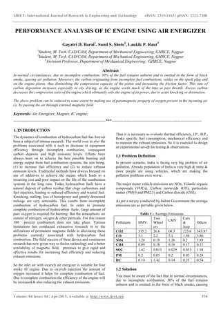
- 1. IJRET: International Journal of Research in Engineering and Technology eISSN: 2319-1163 | pISSN: 2321-7308 _______________________________________________________________________________________ Volume: 04 Issue: 04 | Apr-2015, Available @ http://www.ijret.org 774 PERFORMANCE ANALYSIS OF IC ENGINE USING AIR ENERGIZER Gayatri D. Barai1 , Sunil S. Shete2 , Laukik P. Raut3 1 Student, M. Tech. CAD/CAM, Department of Mechanical Engineering, GHRCE, Nagpur 2 Student, M. Tech. CAD/CAM, Department of Mechanical Engineering, GHRCE, Nagpur 3 Assistant Professor, Department of Mechanical Engineering, GHRCE, Nagpur Abstract In normal circumstances, due to incomplete combustion, 30% of the fuel remains unburnt and is emitted in the form of black smoke, causing air pollution. Moreover, the carbon originating from incomplete fuel combustions, settles on the spark plug and on the engine piston, thus diminishing the compression capacity of the piston and increasing the friction factor. This rate of carbon deposition increases especially in city driving, as the engine works much of the time at part throttle. Excess carbon decreases the compression ratio of the engine which ultimately robs the engine of its power, due to acute knocking or detonation. The above problem can be reduced to some extent by making use of paramagnetic property of oxygen present in the incoming air i.e. by passing the air through external magnetic field. Keywords: Air Energizer, Magnet, IC engine; --------------------------------------------------------------------***------------------------------------------------------------------ 1. INTRODUCTION The dynamics of combustion of hydrocarbon fuel has forever been a subject of intense research. The world over as also the problems associated with it such as decrease in equipment efficiency through incomplete combustion, consequent carbon deposits and high emission levels. Efforts have always been on to achieve the best possible burning and energy output from fuel combustion systems, the aim being, (1) to increase fuel efficiency and (2) to reduce exhaust emission levels. Traditional methods have always focused on use of additives to achieve the means which leads to a recurring cost and poor impact on the life of the combustion systems in the long runs. Today hydrocarbon fuels have a natural deposit of carbon residue that clogs carburetors and fuel injectors, leading to reduced efficiency and wasted fuel. Knocking, stalling, loss of horsepower and greatly decreased mileage are very noticeable. This results from incomplete combustion of hydrocarbon fuel. In order to promote complete combustion of hydrocarbon fuels , large amount of pure oxygen is required for burning. But the atmospheric air consist of nitrogen, oxygen & other particals. For this reason 100 percent combustion does not take place. Various institutions has conducted exhaustive research in to the utilizations of permanent magnetic fields in alleviating these problems currently associated with hydrocarbon fuel combustion. The field success of these device and continuous research has now given way to fusion technology and a better availability of magnetic field, promises to give rapid and effective results for increasing fuel efficiency and reducing exhaust emissions. So the inlet air with oxyrich air energizer is suitable for four stroke SI engine. Due to oxyrich injection the amount of oxygen increased it helps for complete combustion of fuel. Due to complete combustion the efficiency of the engine will be increased & also reducing the exhaust emissions. Thus it is necessary to evaluate thermal efficiency, I.P., B.P., Brake specific fuel consumption, mechanical efficiency and to measure the exhuast emissions. So it is essential to design an experimental set-up for testing & observations. 1.1 Problem Definition In present scenario, India is facing very big problem of air pollution. Already population of India is very high & more & more people are using vehicles, which are making the pollution problems even worse. The major motor vehicle emissions are NOx, Volatile organic compounds (VOCs), Carbon monoxide (CO), particulate matter (PM10 and PM2.5) and Carbon dioxide (CO2). As per a survey conducted by Indian Government the average emissions are as per table given below. Table 1 - Average Emissions Pollutants HMV Two Wheel ers LMV Cars & Jeep Others CO2 515.2 26.6 60.3 223.6 343.87 CO 5.1 2.2 5.1 1.98 3.86 NOx 1.28 0.19 1.28 0.2 3.89 CH4 0.09 0.18 0.18 0.17 0.11 SO2 1.42 0.013 0.029 0.053 1.94 PM 0.2 0.05 0.2 0.03 0.24 HC 0.14 1.42 0.14 0.25 0.54 1.2 Solution You must be aware of the fact that in normal circumstances, due to incomplete combustion, 30% of the fuel remains unburnt and is emitted in the form of black smoke, causing
- 2. IJRET: International Journal of Research in Engineering and Technology eISSN: 2319-1163 | pISSN: 2321-7308 _______________________________________________________________________________________ Volume: 04 Issue: 04 | Apr-2015, Available @ http://www.ijret.org 775 air pollution. Moreover, the carbon originating from incomplete fuel combustions, settles on the spark plug and on the engine piston, thus diminishing the compression capacity of the piston and increasing the friction factor. This rate of carbon deposition, increases especially in city driving, as the engine works much of the time at part throttle. Excess carbon decreases the compression ratio of the engine which ultimately robs the engine of its power, due to acute knocking or detonation. The above problem can be reduced to some extent by making use of PARAMAGNETIC property of oxygen present in the incoming air i.e- by passing the air through external magnetic field. 2. CONCEPT An Air Energizer is nothing but a simple pair of magnets which is used to magnetize the incoming air. It is installed on intake manifold pipe as well as air intake pipe. After installation of magnets on pipes it creates magnetic field which magnetizes the paramagnetic oxygen in air. This helps to improve combustion in engine. Fig 1 - Air Energizer Air Energizer is an apparatus which ensures complete combustion in an IC Engine. It improves combustion efficiency and gives extra mileage and power of I.C. Engine. It ensures minimum deposition of carbon on the spark plug and on the engine piston head improves compression capacity of the piston helping in the reduction in noise and vibration. 2.1 Magnet Installation Fig 2 - Magnets installed on Intake Manifold Fig 3 - Magnets installed on Air Intake Pipe 3. WORKING Fig 4 - Place of Air Energizer The Fuel saving device uses the principle of magnetically induced ionization. Most people see magnets as something a child plays with but magnetism is a science in its own right and is partly responsible for the electronic age we live in as without magnets we would not have electricity. We live on a giant magnet with a North and South Pole. It is this magnet, our planet Earth, which attracts ions from damaging cosmic rays and collects them in a protective barrier known as the ionosphere. Magnets have their own unique magnetic fields and lines of force. Man-made magnets range from a steel bar to complex compositions of rare and expensive elements, each to produce a different effect for varying applications. 3.1 Phenomenon Atoms that possess an odd number of protons and /or neutrons will alter their normal chaotic nuclear spins and line those spins in relationship to a strong external magnetic field. When the magnets are installed on air intake pipe, opposite poles of magnets creates the magnetic field. When air is
- 3. IJRET: International Journal of Research in Engineering and Technology eISSN: 2319-1163 | pISSN: 2321-7308 _______________________________________________________________________________________ Volume: 04 Issue: 04 | Apr-2015, Available @ http://www.ijret.org 776 passed through this field, the oxygen in the air gets positively charged as well as gets aligned. Because of the negatively charged fuel molecules, the positively charged oxygen molecules are able to get all around the fuel molecules. This helps in quick combustion of air fuel mixture with minimum emissions. 3.2 Components of the Computerized Test Rig - Computerized Engine Test Rig consists of the following systems. 1) Dynamometer – Hydraulic or Eddy Current type with computerized torque measuring system 2) Engine fitted with a Piezo-sensor for pressure measurement 3) Connection between Dynamometer and Engine 4) Computerized air flow measurement system 5) Computerized fuel flow measurement system 6) Computerized water flow measurement system 7) Exhaust gas calorimeter with computerized temperature measurement system 8) Engine combustion analysis system 3.2.1. Dynamometer The Dynamometer is of eddy current type and the information is included in a separate manual provided with this setup. The control and excitation unit is mounted on a separate panel. 3.2.2. Engine Engine is TATA make engine with following specifications – Rated Power 63.5 BHP 5000 RPM Bore –75 mm Stroke –79.50 mm Connecting Rod Length – 145mm Compression Ratio – 9.50: 1 Type – 4 Stroke, 4 Cylinder, MPFI, Water cooled, Petrol engine Piezo Pressure Transducer is PCB Piezotronics make – model 111A22. Table 2 - Test Rig Specifications Test Performed Date 25/04/2013 Test Rig Manufacturer Engine Type 4 Stroke,4 Cylinder, MPFI Petrol- Water Cooled M/S. Accurate Test Equipments & Engineeers, Engine Make & Model TATA INDICA Petrol BSIII Table 3 Engine Specification Bore(mm) 75.00 Conn. Rod Length(mm) 145.00 Stroke(mm) 79.50 Swept Volume (C.C.) 1405.00 C.R 9.50 3.2.3. Connection between Dynamometer & Engine The Dynamometer and Engine are connected by means of a cardan shaft having Universal Joints at both ends and splined shaft for facilitating the movement along the axis of shaft A MS fabricated guard is provided to reduce the impact in case of failure of the shaft during testing. 3.2.4. Computerized Air Flow Measurement Systems For Air Flow measurement, the principle of pressure drop across a thin edged orifice plate It consists of a MS fabricated Air box with an orifice plate assembly at one end and a rubber diaphragm for compensating the effect the pressure drop inside the box. The Air box is designed to damp the air pulsations due to cylinder suction etc. The output is tapped across the orifice and given to U Tube manometer. The pressure drop in mm of water column can be measured and further used in air flow calculations. One branch of this air pressure tap is given to low pressure measurement side of a differential pressure transmitter which can accurately amplify the signal. The DP transmitter has 4 to 20 mA output corresponding to 0 – 250 mm of water column The manometer pressure drop is read our at the Universal Input Scanner – Channel No. 7 3.2.5. Fuel Flow Measurement Systems For fuel flow measurement, time required for fuel consumption between for certain amount of fuel weight consumed is measured. It consists of a MS fabricated box in which a fuel pump is fitted and mounted. The time required for 100 Gram of Fuel is to be measured by stop watch and entered into the software before saving the data. 3.2.6. Water Flow Measurement System For Water Flow measurement, a Rotameter is used. The flow rate is same for the calorimeter as well as engine. The value of Flow rate in LPH is to be entered into software before saving the data. The flow rate should be adjusted to approx. 300 to 500 LPH so as to maintain engine water outlet temperature to 60 to 80 degree Centigrade. 3.2.7. Exhaust Gas Calorimeter System This is used to deriving the Mg x CPg value for Gases of Combustion which are delivered through exhaust. The calorimeter is a Cross Flow, Tube in Shell type Heat Exchanger.
- 4. IJRET: International Journal of Research in Engineering and Technology eISSN: 2319-1163 | pISSN: 2321-7308 _______________________________________________________________________________________ Volume: 04 Issue: 04 | Apr-2015, Available @ http://www.ijret.org 777 The Exhaust Gases flow through the pipes and water flowing through the jacket cools the gases. Knowing the Calorific value of water, flow rate of water and the Gas and water temperatures at inlet and outlet of calorimeter, the Mg x CPg value for Gases can be calculated. 3.2.8. Engine Combustion Analyzer System This is explained in detail in separately and is used to study the combustion pressure data with respect to crank angle and volume. Fig 5 - Exhaust Gas Analyzer Fig 6 - Analyzer Tip 4. OBSERVATIONS 4.1 Readings for Emission Levels: Test 1 Load /Gases No load 10 N.m 20 N.m 30 N.m 40 N.m CO(%) 1.927 2.017 2.046 2.246 2.403 HC(ppm) 117 125 181 183 193 CO2(%) 10.2 10.3 10.4 10.4 10.5 O2(%) 5.64 5.23 4.96 4.68 4.55 NOx(ppm) 76 122 278 320 444 AFR 18 18 17 16 16 Test 2 Load /Gases No load 10 N.m 20 N.m 30 N.m 40 N.m CO(%) 1.774 1.413 1.775 2.343 2.332 HC(ppm) 97 152 164 185 165 CO2(%) 9.80 10.00 9.89 10.30 10.00 O2(%) 6.27 5.88 5.94 4.84 5.23 NOx(ppm) 59 213 259 359 390 AFR 19 19 18 17 17 Test 3 Load /Gases No load 10 N.m 20 N.m 30 N.m 40 N.m CO (%) 2.350 2.568 2.101 2.739 3.032 HC(ppm) 116 120 169 186 187 CO2(%) 10.10 9.60 10.10 10.10 10.30 O2(%) 5.55 5.72 5.53 4.90 4.55 NOx(ppm) 49 91 224 273 323 AFR 17 18 18 17 16 Test 4 Load /Gases No load 10 N.m 20 N.m 30 N.m 40 N.m CO (%) 2.509 1.581 2.160 2.523 2.846 HC(ppm) 113 148 167 174 181 CO2(%) 9.39 10.2 10.3 10.3 10.8 O2(%) 6.27 6.16 5.52 5.22 4.36 NOx(ppm) 59 163 217 274 357 AFR 18 19 17 17 16 5. RESULT COMPARISION LOAD=NO LOAD TRIAL NO /GAS 1 (W/O MAGNET) 2 3 4 CO(%) 1.927 1.774 2.350 2.509 HC(ppm) 117 97 116 113 CO2(%) 10.20 9.80 10.10 9.39 O2(%) 5.64 6.27 5.55 6.27 NOx(ppm) 76 59 49 59 AFR 18 19 17 18 * Green colour indicates decrease in emission. LOAD=10N.m TRIAL NO /GAS 1(W/O MAGNET) 2 3 4 CO(%) 2.017 1.413 2.568 1.581 HC(ppm) 125 152 120 148 CO2(%) 10.30 10.00 9.60 10.20 O2(%) 5.23 5.88 5.72 6.16
- 5. IJRET: International Journal of Research in Engineering and Technology eISSN: 2319-1163 | pISSN: 2321-7308 _______________________________________________________________________________________ Volume: 04 Issue: 04 | Apr-2015, Available @ http://www.ijret.org 778 NOx(ppm) 122 113 91 163 AFR 18 19 18 19 LOAD=20N.m TRIAL NO /GAS 1 (W/O MAGNET) 2 3 4 CO(%) 2.046 1.775 2.101 2.160 HC(ppm) 183pp 164 169 168 CO2(%) 10.40 9.89 10.10 10.30 O2(%) 4.96 5.94 5.53 5.52 NOx(ppm) 278 259 224 217 AFR 17 18 18 17 LOAD=30N.m TRIAL NO /GAS 1 (W/O MAGNET) 2 3 4 CO(%) 2.246 2.343 2.739 2.523 HC(ppm) 183 185 186 174 CO2(%) 10.40 10.30 10.10 10.30 O2(%) 4.68 4.84 4.90 5.25 NOx(ppm) 320 359 273 274 AFR 16 17 17 17 LOAD=40N.m TRIAL NO /GAS 1 (W/O MAGNET) 2 3 4 CO(%) 2.403 2.332 3.032 2.846 HC(ppm) 181 165 187 181 CO2(%) 10.50 10.00 10.30 10.80 O2(%) 4.55 5.23 4.55 4.36 NOx(ppm) 444 390 323 357 AFR 16 17 16 16 The above tables show the comparison of the various gaseous emissions in percentage or ppm. It can be seen from above comparison that, there is an appreciable decrease in HC and NOx levels. Considering all the four trials, there is maximum decrease of 20.62% in HC emissions. Moreover, for NOx emissions, 19.59% decrease was observed. 5.1 BSFC Comparison: Trial No /Load 1 2 3 4 No Load 13717.15 11942.02 24305.61 13339.11 10 715.22 388.51 792.83 723.60 20 410.26 261.35 419.13 416.01 30 328.24 255.93 325.43 310.19 40 250.63 743.28 267.95 276.92 5.2 FC Time Comparison Trial no. /Load (Nm) 1 (sec) 2 (sec) 3 (sec) 4 (sec) No load 109.4 121.07 115 102.6 10 107.00 107.90 109.6 113.0 20 97.90 105.4 98.70 100.2 30 87.10 105.4 95.70 91.4 40 80.03 83.7 87.7 85.2 Average 96.286 104.694 101.340 98.48 As shown above, the table shows fuel consumption time for various loads. Comparing their average values, it can be concluded that FC time increases appreciably (about 9-10%). The increase indicates that there is an effective fuel combustion as compared to conventional scenario. It eventually decreases the fuel consumption resulting in increased mileage. 6. CONCLUSION From above experimentation we can conclude that, using Air Energizer technique, there is considerable reduction in following parameters, NOX = 20% (approx.) HC = 19% (approx.) CO2 = 8% (approx.) CO = 3% (approx.) And also the time required for Fuel Consumption increases by about 9-10%. The decrease in emission levels of harmful gases like NOX, COX & CO helps to control the pollution effectively. And there is also increase in mileage about 18 -22%. The further research in this technology can improve mileage, engine efficiency and also can decrease emission level. With the aid of Fuel Energizer this technology can give more appreciable results. REFERENCES [1] S. Bari, M. Mohammad Esmaeil, “Effect of H2/O2 addition in increasing the thermal efficiency of a diesel engine Fuel”, 89 (2010),pp 378–383. [2] P. Govindasamy, S. Dhandapani, “An Experimental Investigation on the effect of Magnetic flux to reduce emissions and improve combustion performance in a four- stroke catalytic coated spark ignition engine”, KSAE International Journal of Automotive Technology”, Paper No.E-2006079. Vol.8, November 5, Year-2007. [3] C Dahnz and U Spicher, “Irregular combustion in supercharged spark ignition engines – pre-ignition and other phenomena”, International Journal of Engine Research 2010 11: 485 published on 3 September 2010. [4] Chih Wu, Paul V. Puzinauskas, Jung S Tsai, “Performance analysis and optimization of a supercharged Miller cycle Otto engine”, Applied Thermal Engineering 23 (2003) 511–521.