1. Architecture of FPGAs and CPLDs: A Tutorial
Stephen Brown and Jonathan Rose
Department of Electrical and Computer Engineering
University of Toronto
email: brown | jayar@eecg.toronto.edu
Abstract
This paper provides a tutorial survey of architectures of commercially available high-capacity
field-programmable devices (FPDs). We first define the relevant terminology in the field and then
describe the recent evolution of FPDs. The three main categories of FPDs are delineated: Simple
PLDs (SPLDs), Complex PLDs (CPLDs) and Field-Programmable Gate Arrays (FPGAs). We
then give details of the architectures of all of the most important commercially available chips,
and give examples of applications of each type of device.
2. 1 Introduction to High-Capacity FPDs
Prompted by the development of new types of sophisticated field-programmable devices (FPDs),
the process of designing digital hardware has changed dramatically over the past few years.
Unlike previous generations of technology, in which board-level designs included large numbers
of SSI chips containing basic gates, virtually every digital design produced today consists mostly
of high-density devices. This applies not only to custom devices like processors and memory, but
also for logic circuits such as state machine controllers, counters, registers, and decoders. When
such circuits are destined for high-volume systems they have been integrated into high-density
gate arrays. However, gate array NRE costs often are too expensive and gate arrays take too long
to manufacture to be viable for prototyping or other low-volume scenarios. For these reasons,
most prototypes, and also many production designs are now built using FPDs. The most compel-
ling advantages of FPDs are instant manufacturing turnaround, low start-up costs, low financial
risk and (since programming is done by the end user) ease of design changes.
The market for FPDs has grown dramatically over the past decade to the point where there is
now a wide assortment of devices to choose from. A designer today faces a daunting task to
research the different types of chips, understand what they can best be used for, choose a particu-
lar manufacturers’s product, learn the intricacies of vendor-specific software and then design the
hardware. Confusion for designers is exacerbated by not only the sheer number of FPDs avail-
able, but also by the complexity of the more sophisticated devices. The purpose of this paper is to
provide an overview of the architecture of the various types of FPDs. The emphasis is on devices
with relatively high logic capacity; all of the most important commercial products are discussed.
Before proceeding, we provide definitions of the terminology in this field. This is necessary
because the technical jargon has become somewhat inconsistent over the past few years as compa-
nies have attempted to compare and contrast their products in literature.
Page 2 of 41
3. 1.1 Definitions of Relevant Terminology
The most important terminology used in this paper is defined below.
• Field-Programmable Device (FPD) — a general term that refers to any type of integrated cir-
cuit used for implementing digital hardware, where the chip can be configured by the end user
to realize different designs. Programming of such a device often involves placing the chip into
a special programming unit, but some chips can also be configured “in-system”. Another name
for FPDs is programmable logic devices (PLDs); although PLDs encompass the same types of
chips as FPDs, we prefer the term FPD because historically the word PLD has referred to rela-
tively simple types of devices.
• PLA — a Programmable Logic Array (PLA) is a relatively small FPD that contains two levels
of logic, an AND-plane and an OR-plane, where both levels are programmable (note: although
PLA structures are sometimes embedded into full-custom chips, we refer here only to those
PLAs that are provided as separate integrated circuits and are user-programmable).
• PAL* — a Programmable Array Logic (PAL) is a relatively small FPD that has a programma-
ble AND-plane followed by a fixed OR-plane
• SPLD — refers to any type of Simple PLD, usually either a PLA or PAL
• CPLD — a more Complex PLD that consists of an arrangement of multiple SPLD-like blocks
on a single chip. Alternative names (that will not be used in this paper) sometimes adopted for
this style of chip are Enhanced PLD (EPLD), Super PAL, Mega PAL, and others.
• FPGA — a Field-Programmable Gate Array is an FPD featuring a general structure that allows
very high logic capacity. Whereas CPLDs feature logic resources with a wide number of inputs
(AND planes), FPGAs offer more narrow logic resources. FPGAs also offer a higher ratio of
flip-flops to logic resources than do CPLDs.
• HCPLDs — high-capacity PLDs: a single acronym that refers to both CPLDs and FPGAs. This
term has been coined in trade literature for providing an easy way to refer to both types of
devices. We do not use this term in the paper.
* PAL is a trademark of Advanced Micro Devices.
Page 3 of 41
4. • Interconnect — the wiring resources in an FPD.
• Programmable Switch — a user-programmable switch that can connect a logic element to an
interconnect wire, or one interconnect wire to another
• Logic Block — a relatively small circuit block that is replicated in an array in an FPD. When a
circuit is implemented in an FPD, it is first decomposed into smaller sub-circuits that can each
be mapped into a logic block. The term logic block is mostly used in the context of FPGAs, but
it could also refer to a block of circuitry in a CPLD.
• Logic Capacity — the amount of digital logic that can be mapped into a single FPD. This is
usually measured in units of “equivalent number of gates in a traditional gate array”. In other
words, the capacity of an FPD is measured by the size of gate array that it is comparable to. In
simpler terms, logic capacity can be thought of as “number of 2-input NAND gates”.
• Logic Density — the amount of logic per unit area in an FPD.
• Speed-Performance — measures the maximum operable speed of a circuit when implemented
in an FPD. For combinational circuits, it is set by the longest delay through any path, and for
sequential circuits it is the maximum clock frequency for which the circuit functions properly.
In the remainder of this section, to provide insight into FPD development the evolution of
FPDs over the past two decades is described. Additional background information is also included
on the semiconductor technologies used in the manufacture of FPDs.
1.2 Evolution of Programmable Logic Devices
The first type of user-programmable chip that could implement logic circuits was the Programma-
ble Read-Only Memory (PROM), in which address lines can be used as logic circuit inputs and
data lines as outputs. Logic functions, however, rarely require more than a few product terms, and
a PROM contains a full decoder for its address inputs. PROMS are thus an inefficient architecture
for realizing logic circuits, and so are rarely used in practice for that purpose. The first device
developed later specifically for implementing logic circuits was the Field-Programmable Logic
Array (FPLA), or simply PLA for short. A PLA consists of two levels of logic gates: a program-
Page 4 of 41
5. Inputs & Flip−flop feedbacks
D
D
¡
AND
D
Outputs
Plane D
D
D
Figure 1 - Structure of a PAL.
mable “wired” AND-plane followed by a programmable “wired” OR-plane. A PLA is structured
so that any of its inputs (or their complements) can be AND’ed together in the AND-plane; each
AND-plane output can thus correspond to any product term of the inputs. Similarly, each OR-
plane output can be configured to produce the logical sum of any of the AND-plane outputs. With
this structure, PLAs are well-suited for implementing logic functions in sum-of-products form.
They are also quite versatile, since both the AND terms and OR terms can have many inputs (this
feature is often referred to as wide AND and OR gates).
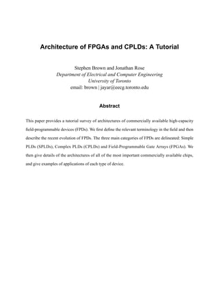
When PLAs were introduced in the early 1970s, by Philips, their main drawbacks were that
they were expensive to manufacture and offered somewhat poor speed-performance. Both disad-
vantages were due to the two levels of configurable logic, because programmable logic planes
were difficult to manufacture and introduced significant propagation delays. To overcome these
weaknesses, Programmable Array Logic (PAL) devices were developed. As Figure 1 illustrates,
PALs feature only a single level of programmability, consisting of a programmable “wired” AND-
plane that feeds fixed OR-gates. To compensate for lack of generality incurred because the OR-
Page 5 of 41
6. plane is fixed, several variants of PALs are produced, with different numbers of inputs and out-
puts, and various sizes of OR-gates. PALs usually contain flip-flops connected to the OR-gate out-
puts so that sequential circuits can be realized. PAL devices are important because when
introduced they had a profound effect on digital hardware design, and also they are the basis for
some of the newer, more sophisticated architectures that will be described shortly. Variants of the
basic PAL architecture are featured in several other products known by different acronyms. All
small PLDs, including PLAs, PALs, and PAL-like devices are grouped into a single category
called Simple PLDs (SPLDs), whose most important characteristics are low cost and very high
pin-to-pin speed-performance.
As technology has advanced, it has become possible to produce devices with higher capacity
than SPLDs. The difficulty with increasing capacity of a strict SPLD architecture is that the struc-
ture of the programmable logic-planes grow too quickly in size as the number of inputs is
increased. The only feasible way to provide large capacity devices based on SPLD architectures is
then to integrate multiple SPLDs onto a single chip and provide interconnect to programmably
connect the SPLD blocks together. Many commercial FPD products exist on the market today
with this basic structure, and are collectively referred to as Complex PLDs (CPLDs).
CPLDs were pioneered by Altera, first in their family of chips called Classic EPLDs, and then
in three additional series, called MAX 5000, MAX 7000 and MAX 9000. Because of a rapidly
growing market for large FPDs, other manufacturers developed devices in the CPLD category and
there are now many choices available. All of the most important commercial products will be
described in Section 2. CPLDs provide logic capacity up to the equivalent of about 50 typical
SPLD devices, but it is somewhat difficult to extend these architectures to higher densities. To
build FPDs with very high logic capacity, a different approach is needed.
Page 6 of 41
7. The highest capacity general purpose logic chips available today are the traditional gate arrays
sometimes referred to as Mask-Programmable Gate Arrays (MPGAs). MPGAs consist of an array
of pre-fabricated transistors that can be customized into the user’s logic circuit by connecting the
transistors with custom wires. Customization is performed during chip fabrication by specifying
the metal interconnect, and this means that in order for a user to employ an MPGA a large setup
cost is involved and manufacturing time is long. Although MPGAs are clearly not FPDs, they are
mentioned here because they motivated the design of the user-programmable equivalent: Field-
Programmable Gate Arrays (FPGAs). Like MPGAs, FPGAs comprise an array of uncommitted
circuit elements, called logic blocks, and interconnect resources, but FPGA configuration is per-
formed through programming by the end user. An illustration of a typical FPGA architecture
appears in Figure 2. As the only type of FPD that supports very high logic capacity, FPGAs have
been responsible for a major shift in the way digital circuits are designed.
Logic
Block
I/O Block
Figure 2 - Structure of an FPGA.
Page 7 of 41
8. Figure 3 summarizes the categories of FPDs by listing the logic capacities available in each of
the three categories. In the figure, “equivalent gates” refers loosely to “number of 2-input NAND
gates”. The chart serves as a guide for selecting a specific device for a given application, depend-
ing on the logic capacity needed. However, as we will discuss shortly, each type of FPD is inher-
ently better suited for some applications than for others. It should also be mentioned that there
exist other special-purpose devices optimized for specific applications (e.g. state machines, ana-
log gate arrays, large interconnection problems). However, since use of such devices is limited
they will not be described here. The next sub-section discusses the methods used to implement the
user-programmable switches that are the key to the user-customization of FPDs.
1.3 User-Programmable Switch Technologies
The first type of user-programmable switch developed was the fuse used in PLAs. Although fuses
are still used in some smaller devices, we will not discuss them here because they are quickly
being replaced by newer technology. For higher density devices, where CMOS dominates the IC
industry, different approaches to implementing programmable switches have been developed. For
CPLDs the main switch technologies (in commercial products) are floating gate transistors like
40000 ***
20000
¢
Equivalent 12000 **
£
Gates
5000 *
2000
¢
1000
Legend
200
¢
*** Altera FLEX 10000, AT&T ORCA 2
** Altera MAX 9000
* Altera MAX 7000, AMD Mach, Lattice (p)LSI, Cypress FLASH370, Xilinx XC9500
¤ ¥
SPLDs CPLDs FPGAs
Figure 3 - FPD Categories by Logic Capacity.
Page 8 of 41
9. those used in EPROM and EEPROM, and for FPGAs they are SRAM and antifuse. Each of these
is briefly discussed below.
An EEPROM or EPROM transistor is used as a programmable switch for CPLDs (and also
for many SPLDs) by placing the transistor between two wires in a way that facilitates implemen-
tation of wired-AND functions. This is illustrated in Figure 4, which shows EPROM transistors as
they might be connected in an AND-plane of a CPLD. An input to the AND-plane can drive a
product wire to logic level ‘0’ through an EPROM transistor, if that input is part of the corre-
sponding product term. For inputs that are not involved for a product term, the appropriate
EPROM transistors are programmed to be permanently turned off. A diagram for an EEPROM-
based device would look similar.
Although there is no technical reason why EPROM or EEPROM could not be applied to
FPGAs, current commercial FPGA products are based either on SRAM or antifuse technologies,
as discussed below.
An example of usage of SRAM-controlled switches is illustrated in Figure 5, showing two
applications of SRAM cells: for controlling the gate nodes of pass-transistor switches and to con-
+5 V ¦
¦
input wire input wire
product wire
EPROM EPROM
Figure 4 - EPROM Programmable Switches.
Page 9 of 41
10. Logic Cell Logic Cell
§
SRAM
§
§
SRAM
SRAM
Logic Cell Logic Cell
Figure 5 - SRAM-controlled Programmable Switches.
trol the select lines of multiplexers that drive logic block inputs. The figures gives an example of
the connection of one logic block (represented by the AND-gate in the upper left corner) to
another through two pass-transistor switches, and then a multiplexer, all controlled by SRAM
cells. Whether an FPGA uses pass-transistors or multiplexers or both depends on the particular
product.
The other type of programmable switch used in FPGAs is the antifuse. Antifuses are origi-
nally open-circuits and take on low resistance only when programmed. Antifuses are suitable for
FPGAs because they can be built using modified CMOS technology. As an example, Actel’s anti-
fuse structure, known as PLICE [Ham88], is depicted in Figure 6. The figure shows that an anti-
fuse is positioned between two interconnect wires and physically consists of three sandwiched
layers: the top and bottom layers are conductors, and the middle layer is an insulator. When
unprogrammed, the insulator isolates the top and bottom layers, but when programmed the insula-
tor changes to become a low-resistance link. PLICE uses Poly-Si and n+ diffusion as conductors
Page 10 of 41
11. e oxide
wir ¨
Poly−Si
dielectric
wire
antifuse
n+ diffision
silicon substrate
Figure 6 - Actel Antifuse Structure.
and ONO (see [Ham88]) as an insulator, but other antifuses rely on metal for conductors, with
amorphous silicon as the middle layer [Birk92][Marp94].
Table 1 lists the most important characteristics of the programming technologies discussed in
this section. The left-most column of the table indicates whether the programmable switches are
one-time programmable (OTP), or can be re-programmed (RP). The next column lists whether the
switches are volatile, and the last column names the underlying transistor technology.
Name Re-programmable Volatile Technology
Fuse no no Bipolar
EPROM yes no UVCMOS
out of circuit
EEPROM yes no EECMOS
in circuit
SRAM yes yes CMOS
in circuit
Antifuse no no CMOS+
Table 1 - Summary of Programming Technologies.
Page 11 of 41
12. 1.4 Computer Aided Design (CAD) Flow for FPDs
When designing circuits for implementation in FPDs, it is essential to employ Computer-Aided
Design (CAD) programs. Such software tools are discussed briefly in this section to provide a feel
for the design process involved.
CAD tools are important not only for complex devices like CPLDs and FPGAs, but also for
SPLDs. A typical CAD system for SPLDs would include software for the following tasks: initial
design entry, logic optimization, device fitting, simulation, and configuration. This design flow is
illustrated in Figure 7, which also indicates how some stages feed back to others. Design entry
may be done either by creating a schematic diagram with a graphical CAD tool, by using a text-
based system to describe a design in a simple hardware description language, or with a mixture of
design entry methods. Since initial logic entry is not usually in an optimized form, algorithms are
employed to optimize the circuits, after which additional algorithms analyse the resulting logic
equations and “fit” them into the SPLD. Simulation is used to verify correct operation, and the
user would return to the design entry step to fix errors. When a design simulates correctly it can be
loaded into a programming unit and used to configure an SPLD. One final detail to note about Fig-
ure 7 is that while the original design entry step is performed manually by the designer, all other
steps are carried out automatically by most CAD systems.
fix errors
merge & optimize device simulate
text entry translate equations fitter SPLD
schematic Programming Unit
capture configuration
file
manual automatic
Figure 7 - CAD Design Flow for SPLDs.
Page 12 of 41
13. The steps involved for implementing circuits in CPLDs are similar to those for SPLDs, but the
tools themselves are more sophisticated. Because the devices are complex and can accommodate
large designs, it is more common to use a mixture of design entry methods for different modules
of a complete circuit. For instance, some modules might be designed with a small hardware
description language like ABEL, others drawn using a symbolic schematic capture tool, and still
others described via a full-featured hardware description language such as VHDL. Also, for
CPLDs the process of “fitting” a design may require steps similar to those described below for
FPGAs, depending on how sophisticated the CPLD is. The necessary software for these tasks is
supplied either by the CPLD manufacturer or a third party.
The design process for FPGAs is similar to that for CPLDs, but additional tools are needed to
support the increased complexity of the chips. The major difference is in the “device fitter” step
that comes after logic optimization and before simulation, where FPGAs require at least three
steps: a technology mapper to map from basic logic gates into the FPGA’s logic blocks, placement
to choose which specific logic blocks to use in the FPGA, and a router to allocate the wire seg-
ments in the FPGA to interconnect the logic blocks. With this added complexity, the CAD tools
might require a fairly long period of time (often more than an hour or even several hours) to com-
plete their tasks.
2 Overview of Commercially Available FPDs
This section provides many examples of commercial FPD products. SPLDs are first discussed
briefly, and then details are given for all of the most important CPLDs and FPGAs. The reader
who is interested in more details on the commercial products is encouraged to contact the manu-
facturers, or their distributors, for the latest data sheets*.
* Most FPD manufacturers now provide their data sheets on the world wide web, and can be located
at URL “http://www.companyname.com”.
Page 13 of 41
14. 2.1 Commercially Available SPLDs
As the staple for digital hardware designers for the past two decades, SPLDs are very important
devices. SPLDs represent the highest speed-performance FPDs available, and are inexpensive.
However, they are also fairly straight-forward and well understood, so this paper will discuss
them only briefly.
Two of the most popular SPLDs are the PALs produced by Advanced Micro Devices (AMD)
known as the 16R8 and 22V10. Both of these devices are industry standards and are widely sec-
ond-sourced by various companies. The name “16R8” means that the PAL has a maximum of 16
inputs (there are 8 dedicated inputs and 8 input/outputs), and a maximum of 8 outputs. The “R”
refers to the type of outputs provided by the PAL and means that each output is “registered” by a
D flip-flop. Similarly, the “22V10” has a maximum of 22 inputs and 10 outputs. Here, the “V”
means each output is “versatile” and can be configured in various ways, some configurations reg-
istered and some not.
Another widely used and second sourced SPLD is the Altera Classic EP610. This device is
similar in complexity to PALs, but it offers more flexibility in the way that outputs are produced
and has larger AND- and OR- planes. In the EP610, outputs can be registered and the flip-flops
are configurable as any of D, T, JK, or SR.
In addition to the SPLDs mentioned above many other products are available from a wide
array of companies. All SPLDs share common characteristics, like some sort of logic planes
(AND, OR, NOR, or NAND), but each specific product offers unique features that may be partic-
ularly attractive for some applications. A partial list of companies that offer SPLDs includes:
AMD, Altera, ICT, Lattice, Cypress, and Philips-Signetics. Since some of these SPLDs have com-
plexity approaching that found in CPLDs, the paper will now move on to more sophisticated
devices.
Page 14 of 41
15. I/O
LAB
Block
PIA
Figure 8 - Altera MAX 7000 Series.
2.2 Commercially Available CPLDs
As stated earlier, CPLDs consist of multiple SPLD-like blocks on a single chip. However, CPLD
products are much more sophisticated than SPLDs, even at the level of their basic SPLD-like
blocks. In this section, CPLDs are discussed in detail, first by surveying the available commercial
products and then by discussing the types of applications for which CPLDs are best suited. Suffi-
cient details are presented to allow a comparison between the various competing products, with
more attention being paid to devices that we believe are in more widespread use than others.
2.2.1 Altera CPLDs
Altera has developed three families of chips that fit within the CPLD category: MAX 5000,
MAX 7000, and MAX 9000. Here, the discussion will focus on the MAX 7000 series, because it
is widely used and offers state-of-the-art logic capacity and speed-performance. MAX 5000 rep-
resents an older technology that offers a cost effective solution, and MAX 9000 is similar to MAX
7000, except that MAX 9000 offers higher logic capacity (the industry’s highest for CPLDs).
The general architecture of the Altera MAX 7000 series is depicted in Figure 8. It comprises
an array of blocks called Logic Array Blocks (LABs), and interconnect wires called a Program-
Page 15 of 41
16. mable Interconnect Array (PIA). The PIA is capable of connecting any LAB input or output to
any other LAB. Also, the inputs and outputs of the chip connect directly to the PIA and to LABs.
A LAB can be thought of as a complex SPLD-like structure, and so the entire chip can be consid-
ered to be an array of SPLDs. MAX 7000 devices are available both based in EPROM and
EEPROM technology. Until recently, even with EEPROM, MAX 7000 chips could be program-
mable only “out-of-circuit” in a special-purpose programming unit; however, in 1996 Altera
released the 7000S series, which is reprogrammable “in-circuit”.
The structure of a LAB is shown in Figure 9. Each LAB consists of two sets of eight macro-
cells (shown in Figure 10), where a macrocell comprises a set of programmable product terms
(part of an AND-plane) that feeds an OR-gate and a flip-flop. The flip-flops can be configured as
D type, JK, T, SR, or can be transparent. As illustrated in Figure 10, the number of inputs to the
Array of 16
Macrocells
I/O Control Block
P
to I/O Cells
I
A
product-term sharing
to other LABs
from I/O pins
LAB
Figure 9 - Altera MAX 7000 Logic Array Block (LAB).
Page 16 of 41
17. OR-gate in a macrocell is variable; the OR-gate can be fed from any or all of the five product
terms within the macrocell, and in addition can have up to 15 extra product terms from macrocells
in the same LAB. This product term flexibility makes the MAX 7000 series LAB more efficient in
terms of chip area because typical logic functions do not need more than five product terms, and
the architecture supports wider functions when they are needed. It is interesting to note that vari-
able sized OR-gates of this sort are not available in basic SPLDs (see Figure 1). Similar features
of this kind are found in other CPLD architectures discussed shortly.
Besides Altera, several other companies produce devices that can be categorized as CPLDs.
For example, AMD manufacturers the Mach family, Lattice has the (i)pLSI series, Xilinx pro-
duces a CPLD series that they call XC7000 (unrelated to the Altera MAX 7000 series) and has
announced a new family called XC9500, and ICT has the PEEL array. These devices are dis-
cussed in the following sub-sections.
inputs from other
macrocells in LAB Global clock
set
state
S
D Q
PIA
R
array clock
clear
(global clear
to PIA
not shown)
Local LAB Product Select
Interconnect
Matrix
Figure 10 - MAX 7000 Macrocell.
Page 17 of 41
18. Central Switch Matrix 34V16 PAL
I/O (32)
I/O (8) I/O (8)
I/O (8) I/O (8)
I (12) clk (4)
I/O (8) I/O (8)
I/O (8) I/O (8)
I/O (32)
Figure 11 - Structure of AMD Mach 4 CPLDs.
2.2.2 Advanced Micro Devices (AMD) CPLDs
AMD offers a CPLD family with five sub-families called Mach 1 to Mach 5. Each Mach device
comprises multiple PAL-like blocks: Mach 1 and 2 consist of optimized 22V16 PALs, and Mach 3
and 4 comprise several optimized 34V16 PALs, and Mach 5 is similar but offers enhanced speed-
performance. All Mach chips are based on EEPROM technology, and together the five sub-fami-
lies provide a wide range of selection, from small, inexpensive chips to larger state-of-the-art
ones. This discussion will focus on Mach 4, because it represents the most advanced currently
available parts in the Mach family.
Figure 11 depicts a Mach 4 chip, showing the multiple 34V16 PAL-like blocks, and the inter-
connect, called Central Switch Matrix, for connecting the blocks together. Chips range in size
from 6 to 16 PAL blocks, which corresponds roughly to 2000 to 5000 equivalent gates and are in-
circuit programmable. All connections in Mach 4 between one PAL block and another (even from
a PAL block to itself) are routed through the Central Switch Matrix. The device can thus be
Page 18 of 41
20. 2.2.3 Lattice CPLDs
Lattice offers a complete range of CPLDs, with two main product lines: the Lattice pLSI consist
of three families of EEPROM CPLDs, and the ispLSI are the same as the pLSI devices, except
that they are in-system programmable. For both the pLSI and ispLSI products, Lattice offers three
families that have different logic capacities and speed-performance.
Lattice’s earliest generation of CPLDs is the pLSI and ispLSI 1000 series. Each chip consists
of a collection of SPLD-like blocks, described in more detail later, and a global routing pool to
connect blocks together. Logic capacity ranges from about 1200 to 4000 gates. Pin-to-pin delays
are 10 nsec. Lattice also offers a CPLD family called the 2000 series, which are relatively small
CPLDs, with between 600 and 2000 gates that offer a higher ratio of macrocells to I/O pins and
higher speed-performance than the 1000 series. At 5.5 nsec pin-to-pin delays, the 2000 series
offers state-of-the-art speed.
Lattice’s 3000 series represents their largest CPLDs, with up to 5000 gates. Pin-to-pin delays
for this device are about 10-15 nsec. In terms of other chips discussed so far, the 3000 series func-
tionality is most similar to AMD’s Mach 4. The 3000 series offers some enhancements over the
other Lattice parts to support more recent design styles, such as JTAG boundary scan.
The general structure of a Lattice pLSI or ispLSI device is indicated in Figure 13. Around the
outside edges of the chip are the bi-directional I/Os, which are connected both to the Generic
Logic Blocks (GLBs) and the Global Routing Pool (GRP). As the fly-out on the right side of the
figure shows, the GLBs are small PAL-like blocks that consist of an AND-plane, product term
allocator, and macrocells. The GRP is a set of wires that span the entire chip and are available to
connect the GLB inputs and outputs together. All interconnections pass through the GRP, so tim-
ing between levels of logic in the Lattice chips is fully predictable, much as it is for the AMD
Mach devices.
Page 20 of 41
21. 2.2.4 Cypress FLASH370 CPLDs
Cypress has recently developed a family of CPLD products that are similar to both the AMD
and Lattice devices in several ways. The Cypress CPLDs, called FLASH370 are based on FLASH
EEPROM technology, and offer speed-performance of 8.5 to 15 nsec pin-to-pin delays. The
FLASH370 parts are not in-system programmable. Recognizing that larger chips need more I/Os,
FLASH370 provides more I/Os than competing products, featuring a linear relationship between
the number of macrocells and number of bi-directional I/O pins. The smallest parts have 32 mac-
rocells and 32 I/Os and the largest 256 macrocells and 256 I/Os.
Figure14 shows that FLASH370 has a typical CPLD architecture with multiple PAL-like
blocks and a programmable interconnect matrix (PIM) to connect them. Within each PAL-like
block, there is an AND-plane that feeds a product term allocator that directs from 0 to 16 product
terms to each of 32 OR-gates. Note that in the feed-back path from the macrocell outputs to the
Output
Generic Logic
Routing Pool Blocks
Global Routing Pool
AND product
macrocells
plane term
allocator
Input Bus
I/O Pads
Figure 13 - Lattice (i)PLSI Architecture.
Page 21 of 41
22. PIM
Figure 14 - Architecture of Cypress FLASH370 CPLDs.
PIM, there are 32 wires; this means that a macrocell can be buried (not drive an I/O pin) and yet
the I/O pin that could be driven by the macrocell can still be used as an input. This illustrates
another type of flexibility available in PAL-like blocks in CPLDs, but not present in normal PALs.
2.2.5 Xilinx XC7000 CPLDs
Although Xilinx is mostly a manufacturer of FPGAs, they also offer a selection of CPLDs, called
XC7000, and have announced a new CPLD family called XC9500. There are two main families
in the XC7000 offering: the 7200 series, originally marketed by Plus Logic as the Hiper EPLDs,
and the 7300 series, developed by Xilinx. The 7200 series are moderately small devices, with
about 600 to 1500 gates capacity, and they offer speed-performance of about 25 nsec pin-to-pin
delays. Each chip consists of a collection of SPLD-like blocks that each have 9 macrocells. The
macrocells in the 7200 series are different from those in other CPLDs in that each macrocell
includes two OR-gates and each of these OR-gates is input to a two-bit Arithmetic Logic Unit
(ALU). The ALU can produce any functions of its two inputs, and its output feeds a configurable
flip-flop. The Xilinx 7300 series is an enhanced version of the 7200, offering more capacity (up to
3000 gates when the entire family becomes available) and higher speed-performance. Finally, the
Page 22 of 41
23. new XC9500, when available, will offer in-circuit programmability with 5 nsec pin-to-pin delays
and up to 6200 logic gates.
2.2.6 Altera FLASHlogic CPLDs
Altera’s FLASHlogic, previously known as Intel’s FLEXlogic, features in-system programmabil-
ity and provides on-chip SRAM blocks, a unique feature among CPLD products. The upper part
of Figure 15 illustrates the architecture of FLASHlogic devices; it comprises a collection of PAL-
like blocks, called Configurable Function Blocks (CFBs), that each represents an optimized
24V10 PAL.
I/O I/O I/O I/O
in
global interconnect matrix clk
I/O I/O I/O I/O
10 PAL 24V10
data in
address CFB CFB
128 SRAM
in SRAM in PAL
control
10
mode mode
clk
data out
Figure 15 - Altera FLASHlogic CPLD.
Page 23 of 41
24. In terms of basic structure, FLASHlogic is similar to other products already discussed. How-
ever, they have one unique feature that stands them apart from all other CPLDs: each PAL-like
block, instead of being used for AND-OR logic, can be configured as a block of 10 nsec Static
RAM. This concept is illustrated in the lower part of Figure 15, which shows one CFB being used
as a PAL and another configured as an SRAM. In the SRAM configuration, the PAL block
becomes a 128 word by 10 bit read/write memory. Inputs that would normally feed the AND-
plane in the PAL in this case become address lines, data in, and control signals for the memory.
Notice that the flip-flops and tri-state buffers are still available when the PAL block is configured
as memory.
In the FLASHlogic device, the AND-OR logic plane’s configuration bits are SRAM cells that
are “shadowed” by EPROM or EEPROM cells. The SRAM cells are loaded with a copy of the
non-volatile EPROM or EEPROM memory when power is applied, but it is the SRAM cells that
control the configuration of the chip. It is possible to re-configure the chips in-system by down-
loading new information into the SRAM cells. The SRAM cells’ contents can be written back to
the EEPROM, so that non-volatile re-programming (in-circuit) is available.
2.2.7 ICT PEEL Arrays
The ICT PEEL Arrays are basically large PLAs that include logic macrocells with flop-flops
and feedback to the logic planes. This structure is illustrated by Figure 16, which shows a pro-
grammable AND-plane that feeds a programmable OR-plane. The outputs of the OR-plane are
divided into groups of four, and each group can be input to any of the logic cells. The logic cells
provide registers for the sum terms and can feed-back the sum terms to the AND-plane. Also, the
logic cells connect sum terms to I/O pins.
Because they have a PLA-like structure, logic capacity of PEEL Arrays is somewhat difficult
to measure compared to the CPLDs discussed so far; an estimate is 1600 to 2800 equivalent gates.
Page 24 of 41
25. Figure 16 - Architecture of ICT PEEL Arrays.
PEEL Arrays offer relatively few I/O pins, with the largest part being offered in a 40 pin package.
Since they do not comprise SPLD-like blocks, PEEL Arrays do not fit well into the CPLD cate-
gory, however the are included here because they represent an example of PLA-based, rather than
PAL-based devices, and they offer larger capacity than a typical SPLD.
The logic cell in the PEEL Arrays, depicted in Figure 17, includes a flip-flop, configurable as
D, T, or JK, and two multiplexers. The multiplexers each produce an output of the logic cell and
can provide either a registered or combinational output. One of the logic cell outputs can connect
Figure 17 - Structure of ICT PEEL Array Logic Cell.
Page 25 of 41
26. to an I/O pin and the other output is buried. One of the interesting features of the logic cell is that
the flip-flop clock, as well as preset and clear, are full sum-of-product logic functions. This differs
from all other CPLDs, which simply provide product terms for these signals and is attractive for
some applications. Because of their PLA-like OR-plane, the ICT PEEL Arrays are especially
well-suited to applications that require very wide sum terms.
2.2.8 Applications of CPLDs
We will now briefly examine the types of applications which best suit CPLD architectures.
Because they offer high speeds and a range of capacities, CPLDs are useful for a very wide assort-
ment of applications, from implementing random glue logic to prototyping small gate arrays. One
of the most common uses in industry at this time, and a strong reason for the large growth of the
CPLD market, is the conversion of designs that consist of multiple SPLDs into a smaller number
of CPLDs.
CPLDs can realize reasonably complex designs, such as graphics controller, LAN controllers,
UARTs, cache control, and many others. As a general rule-of-thumb, circuits that can exploit wide
AND/OR gates, and do not need a very large number of flip-flops are good candidates for imple-
mentation in CPLDs. A significant advantage of CPLDs is that they provide simple design
changes through re-programming (all commercial CPLD products are re-programmable). With in-
system programmable CPLDs it is even possible to re-configure hardware (an example might be
to change a protocol for a communications circuit) without power-down.
Designs often partition naturally into the SPLD-like blocks in a CPLD. The result is more pre-
dictable speed-performance than would be the case if a design were split into many small pieces
and then those pieces were mapped into different areas of the chip. Predictability of circuit imple-
mentation is one of the strongest advantages of CPLD architectures.
Page 26 of 41
27. 2.3 Commercially Available FPGAs
As one of the largest growing segments of the semiconductor industry, the FPGA market-place is
volatile. As such, the pool of companies involved changes rapidly and it is somewhat difficult to
say which products will be the most significant when the industry reaches a stable state. For this
reason, and to provide a more focused discussion, we will not mention all of the FPGA manufac-
turers that currently exist, but will instead focus on those companies whose products are in wide-
spread use at this time. In describing each device we will list its capacity, nominally in 2-input
NAND gates as given by the vendor. Gate count is an especially contentious issue in the FPGA
industry, and so the numbers given in this paper for all manufacturers should not be taken too seri-
ously. Wags have taken to calling them “dog” gates, in reference to the traditional ratio between
human and dog years.
There are two basic categories of FPGAs on the market today: 1. SRAM-based FPGAs and 2.
antifuse-based FPGAs. In the first category, Xilinx and Altera are the leading manufacturers in
terms of number of users, with the major competitor being ATT. For antifuse-based products,
Actel, Quicklogic and Cypress, and Xilinx offer competing products.
2.3.1 Xilinx SRAM-based FPGAs
The basic structure of Xilinx FPGAs is array-based, meaning that each chip comprises a two-
dimensional array of logic blocks that can be interconnected via horizontal and vertical routing
channels. An illustration of this type of architecture was shown in Figure 2. Xilinx introduced the
first FPGA family, called the XC2000 series, in about 1985 and now offers three more genera-
tions: XC3000, XC4000, and XC5000. Although the XC3000 devices are still widely used, we
will focus on the more recent and more popular XC4000 family. We note that XC5000 is similar
to XC4000, but has been engineered to offer similar features at a more attractive price, with some
penalty in speed. We should also note that Xilinx has recently introduced an FPGA family based
Page 27 of 41
28. on anti-fuses, called the XC8100. The XC8100 has many interesting features, but since it is not
yet in widespread use, we will not discuss it here. The Xilinx 4000 family devices range in capac-
ity from about 2000 to more than 15,000 equivalent gates.
The XC4000 features a logic block (called a Configurable Logic Block (CLB) by Xilinx) that
is based on look-up tables (LUTs). A LUT is a small one bit wide memory array, where the
address lines for the memory are inputs of the logic block and the one bit output from the memory
is the LUT output. A LUT with K inputs would then correspond to a 2K x 1 bit memory, and can
realize any logic function of its K inputs by programming the logic function’s truth table directly
into the memory. The XC4000 CLB contains three separate LUTs, in the configuration shown in
Figure 18. There are two 4-input LUTS that are fed by CLB inputs, and the third LUT can be used
in combination with the other two. This arrangement allows the CLB to implement a wide range
of logic functions of up to nine inputs, two separate functions of four inputs or other possibilities.
Each CLB also contains two flip-flops.
C1 C2 C3 C4
Inputs
selector
G4 state Outputs
S
G3
Lookup D Q Q2
G2 Table
G1
E R
Lookup
Table G
F4 state
F3 S
Lookup Q Q1
D
F2 Table
F1
E R
Vcc
Clock F
Figure 18 - Xilinx XC4000 Configurable Logic Block (CLB).
Page 28 of 41
29. Toward the goal of providing high density devices that support the integration of entire sys-
tems, the XC4000 chips have “system oriented” features. For instance, each CLB contains cir-
cuitry that allows it to efficiently perform arithmetic (i.e., a circuit that can implement a fast carry
operation for adder-like circuits) and also the LUTs in a CLB can be configured as read/write
RAM cells. A new version of this family, the 4000E, has the additional feature that the RAM can
be configured as a dual port RAM with a single write and two read ports. In the 4000E, RAM
blocks can be synchronous RAM. Also, each XC4000 chip includes very wide AND-planes
around the periphery of the logic block array to facilitate implementing circuit blocks such as
wide decoders.
Besides logic, the other key feature that characterizes an FPGA is its interconnect structure.
The XC4000 interconnect is arranged in horizontal and vertical channels. Each channel contains
some number of short wire segments that span a single CLB (the number of segments in each
channel depends on the specific part number), longer segments that span two CLBs, and very long
segments that span the entire length or width of the chip. Programmable switches are available
(see Figure 5) to connect the inputs and outputs of the CLBs to the wire segments, or to connect
one wire segment to another. A small section of a routing channel representative of an XC4000
device appears in Figure 19. The figure shows only the wire segments in a horizontal channel, and
does not show the vertical routing channels, the CLB inputs and outputs, or the routing switches.
An important point worth noting about the Xilinx interconnect is that signals must pass through
switches to reach one CLB from another, and the total number of switches traversed depends on
the particular set of wire segments used. Thus, speed-performance of an implemented circuit
depends in part on how the wire segments are allocated to individual signals by CAD tools.
Page 29 of 41
30. vertical channels
not shown
CLB CLB CLB CLB CLB
length 1
wires
length 2
wires
long
wires
CLB CLB CLB CLB CLB
Figure 19 - Xilinx XC4000 Wire Segments.
2.3.2 Altera FLEX 8000 and FLEX 10000 FPGAs
Altera’s FLEX 8000 series consists of a three-level hierarchy much like that found in CPLDs.
However, the lowest level of the hierarchy consists of a set of lookup tables, rather than an SPLD-
like block, and so the FLEX 8000 is categorized here as an FPGA. It should be noted, however,
that FLEX 8000 is a combination of FPGA and CPLD technologies. FLEX 8000 is SRAM-based
and features a four-input LUT as its basic logic block. Logic capacity ranges from about 4000
gates to more than 15,000 for the 8000 series.
The overall architecture of FLEX 8000 is illustrated in Figure 20. The basic logic block,
called a Logic Element (LE) contains a four-input LUT, a flip-flop, and special-purpose carry cir-
cuitry for arithmetic circuits (similar to Xilinx XC4000). The LE also includes cascade circuitry
that allows for efficient implementation of wide AND functions. Details of the LE are illustrated
in Figure 21.
In the FLEX 8000, LEs are grouped into sets of 8, called Logic Array Blocks (LABs, a term
borrowed from Altera’s CPLDs). As shown in Figure 22, each LAB contains local interconnect
and each local wire can connect any LE to any other LE within the same LAB. Local interconnect
Page 30 of 41
31. I/O
I/O
FastTrack
interconnect
LAB
(8 Logic Elements
local interconnect)
Figure 20 - Architecture of Altera FLEX 8000 FPGAs.
Cascade out
Cascade in
data1
data2
S
Look−up Cascade D
LE out
data3 Q
Table
data4 R
Carry in Carry
Carry out
cntrl1
set/clear
cntrl2
cntrl3
clock
cntrl4
Figure 21 - Altera FLEX 8000 Logic Element (LE).
Page 31 of 41
32. #
From FastTrack
interconnect cascade, carry
cntrl
2
4
data !
To FastTrack
LE interconnect
4
!
LE To FastTrack
$
interconnect
local interconnect
!
LE To FastTrack
interconnect
to adjacent LAB
Figure 22 - Altera FLEX 8000 Logic Array Block (LAB).
also connects to the FLEX 8000’s global interconnect, called FastTrack. FastTrack is similar to
Xilinx long lines in that each FastTrack wire extends the full width or height of the device. How-
ever, a major difference between FLEX 8000 and Xilinx chips is that FastTrack consists of only
long lines. This makes the FLEX 8000 easy for CAD tools to automatically configure. All Fast-
Track wires horizontal wires are identical, and so interconnect delays in the FLEX 8000 are more
predictable than FPGAs that employ many smaller length segments because there are fewer pro-
grammable switches in the longer paths. Predictability is furthered aided by the fact that connec-
tions between horizontal and vertical lines pass through active buffers.
The FLEX 8000 architecture has been extended in the state-of-the-art FLEX 10000 family.
FLEX 10000 offers all of the features of FLEX 8000, with the addition of variable-sized blocks of
SRAM, called Embedded Array Blocks (EABs). This idea is illustrated in Figure 23, which shows
that each row in a FLEX 10000 chip has an EAB on one end. Each EAB is configurable to serve
as an SRAM block with a variable aspect ratio: 256 x 8, 512 x 4, 1K x 2, or 2K x 1. In addition, an
EAB can alternatively be configured to implement a complex logic circuit, such as a multiplier, by
Page 32 of 41
33. I/O
I/O
EAB
EAB
Figure 23 - Architecture of Altera FLEX 10K FPGAs.
employing it as a large multi-output lookup table. Altera provides, as part of their CAD tools, sev-
eral macro-functions that implement useful logic circuits in EABs. Counting the EABs as logic
gates, FLEX 10000 offers the highest logic capacity of any FPGA, although it is hard to provide
an accurate number.
2.3.3 ATT ORCA FPGAs
ATT’s SRAM-based FPGAs feature an overall structure similar to that in Xilinx FPGAs,
and is called Optimized Reconfigurable Cell Array (ORCA). The ORCA logic block is based on
LUTs, containing an array of Programmable Function Units (PFUs). The structure of a PFU is
shown in Figure 24. A PFU possesses a unique kind of configurability among LUT-based logic
blocks, in that it can be configured in the following ways: as four 4-input LUTs, as two 5-input
LUTs, and as one 6-input LUT. A key element of this architecture is that when used as four 4-
Page 33 of 41
34. %
LUT D Q
%
LUT D Q
switch matrix
%
LUT D Q
%
LUT D Q
Figure 24 - ATT Programmable Function Unit (PFU).
input LUTs, several of the LUTs’ inputs must come from the same PFU input. While this reduces
the apparent functionality of the PFU, it also significantly reduces the cost of the wiring associ-
ated with the chip. The PFU also includes arithmetic circuitry, like Xilinx XC4000 and Altera
FLEX 8000, and like Xilinx XC4000 a PFU can be configured as a RAM block. A recently
announced version of the ORCA chip also allows dual-port and synchronous RAM.
ORCA’s interconnect structure is also different from those in other SRAM-based FPGAs.
Each PFU connects to interconnect that is configured in four-bit buses. This provides for more
efficient support for “system-level” designs, since buses are common in such applications. The
ORCA family has been extended in the ORCA 2 series, and offers very high logic capacity up to
40,000 logic gates. ORCA 2 features a two-level hierarchy of PFUs based on the original ORCA
architecture.
Page 34 of 41
35. 2.3.4 Actel FPGAs
In contrast to FPGAs described above, the devices manufactured by Actel are based on anti-
fuse technology. Actel offers three main families: Act 1, Act 2, and Act 3. Although all three gen-
erations have similar features, this paper will focus on the most recent devices, since they are apt
to be more widely used in the longer term. Unlike the FPGAs described above, Actel devices are
based on a structure similar to traditional gate arrays; the logic blocks are arranged in rows and
there are horizontal routing channels between adjacent rows. This architecture is illustrated in
Figure 25. The logic blocks in the Actel devices are relatively small in comparison to the LUT-
based ones described above, and are based on multiplexers. Figure 26 illustrates the logic block in
the Act 3 and shows that it comprises an AND and OR gate that are connected to a multiplexer-
based circuit block. The multiplexer circuit is arranged such that, in combination with the two
logic gates, a very wide range of functions can be realized in a single logic block. About half of
the logic blocks in an Act 3 device also contain a flip-flop.
I/O Blocks
Logic
Block
Routing Rows
Channels
I/O Blocks
I/O Blocks
I/O Blocks
Figure 25 - Structure of Actel FPGAs.
Page 35 of 41
36. Multiplexer−based
inputs output
Circuit Block
inputs
Figure 26 - Actel Act 3 Logic Module.
As stated above, Actel’s interconnect is organized in horizontal routing channels. The chan-
nels consist of wire segments of various lengths with antifuses to connect logic blocks to wire
segments or one wire to another. Also, although not shown in Figure 25, Actel chips have vertical
wires that overlay the logic blocks, for signal paths that span multiple rows. In terms of speed-per-
formance, it would seem probable that Actel chips are not fully predictable, because the number
of antifuses traversed by a signal depends on how the wire segments are allocated during circuit
implementation by CAD tools. However, Actel provides a rich selection of wire segments of dif-
ferent length in each channel and has developed algorithms that guarantee strict limits on the
number of antifuses traversed by any two-point connection in a circuit which improves speed-per-
formance significantly.
2.3.5 Quicklogic pASIC FPGAs
The main competitor for Actel in antifuse-based FPGAs is Quicklogic, whose has two fami-
lies of devices, called pASIC and pASIC-2. The pASIC-2 is an enhanced version that has only
recently been introduced, and will not be discussed here. The pASIC, as illustrated in Figure 27,
has similarities to several other FPGAs: the overall structure is array-based like Xilinx FPGAs, its
logic blocks use multiplexers similar to Actel FPGAs, and the interconnect consists of only long-
Page 36 of 41
37. amorphous silicon
metal 2
I/O Blocks
metal 1
oxide
ViaLink at
every wire
crossing
Logic Cell
Figure 27 - Structure of Quicklogic pASIC FPGA.
lines like in Altera FLEX 8000. We note that the pASIC architecture is now independently devel-
oped by Cypress as well, but this discussion will focus only on Quicklogic’s version of their parts.
Quicklogic’s antifuse structure, called ViaLink, is illustrated on the left-hand side of Figure
27. It consists of a top layer of metal, an insulating layer of amorphous silicon, and a bottom layer
of metal. When compared to Actel’s PLICE antifuse, ViaLink offers a very low on-resistance of
about 50 ohms (PLICE is about 300 ohms) and a low parasitic capacitance. Figure 27 shows that
ViaLink antifuses are present at every crossing of logic block pins and interconnect wires, provid-
ing generous connectivity. pASIC’s multiplexer-based logic block is depicted in Fig 28. It is more
complex than Actel’s Logic Module, with more inputs and wide (6-input) AND-gates on the mul-
tiplexer select lines. Every logic block also contains a flip-flops.
Page 37 of 41
38. '
QS
'
A1
'
A2
A3 0
AZ
'
'
A4
'
A5
A6
B1
1
OZ
0
2
B2
C1 )
1 D S Q
QZ
(
C2 0
2
D1 1
D2 2
0 R
E1
E2 1
NZ
F1
F2
F3
F4 FZ
F5
F6
QC
QR
Figure 28 - Quicklogic (Cypress) Logic Cell.
2.3.6 Applications of FPGAs
FPGAs have gained rapid acceptance and growth over the past decade because they can be
applied to a very wide range of applications. A list of typical applications includes: random logic,
integrating multiple SPLDs, device controllers, communication encoding and filtering, small to
medium sized systems with SRAM blocks, and many more.
Other interesting applications of FPGAs are prototyping of designs later to be implemented in
gate arrays, and also emulation of entire large hardware systems. The former of these applications
might be possible using only a single large FPGA (which corresponds to a small Gate Array in
terms of capacity), and the latter would entail many FPGAs connected by some sort of intercon-
nect; for emulation of hardware, QuickTurn [Wolff90] (and others) has developed products that
comprise many FPGAs and the necessary software to partition and map circuits.
Another promising area for FPGA application, which is only beginning to be developed, is the
usage of FPGAs as custom computing machines. This involves using the programmable parts to
“execute” software, rather than compiling the software for execution on a regular CPU. The
Page 38 of 41
39. reader is referred to the FPGA-Based Custom Computing Workshop (FCCM) held for the last
four years and published by the IEEE.
It was mentioned in Section 2.2.8 that when designs are mapped into CPLDs, pieces of the
design often map naturally to the SPLD-like blocks. However, designs mapped into an FPGA are
broken up into logic block-sized pieces and distributed through an area of the FPGA. Depending
on the FPGA’s interconnect structure, there may be various delays associated with the intercon-
nections between these logic blocks. Thus, FPGA performance often depends more upon how
CAD tools map circuits into the chip than is the case for CPLDs.
3 Summary and Conclusions
We have presented a survey of field-programmable devices, describing the basic technology that
provides the programmability and a description of many of the architectures in the current mar-
ketplace. This paper has not focussed on the equally important issue of CAD tools for FPDs.
We believe that over time programmable logic will become the dominant form of digital logic
design and implementation. Their ease of access, principally through the low cost of the devices,
makes them attractive to small firms and small parts of large companies. The fast manufacturing
turn-around they provide is an essential element of success in the market. As architecture and
CAD tools improve, the disadvantages of FPDs compared to Mask-Programmed Gate Arrays will
lessen, and programmable devices will dominate.
Page 39 of 41
40. 4 Further Reading
A reasonable introduction to FPGAs can be found in the book:
[Brow92] S. Brown, R. Francis, J. Rose, Z. Vranesic, Field-Programmable Gate Arrays,
Kluwer Academic Publishers, May 1992.
A more specific discussion of three FPGA/CPLD architectures can be found in:
[Trim94] S. Trimberger, Ed., Field-Programmable Gate Array Technology, Kluwer
Academic Publishers, 1994.
More detailed discussion of architectural trade-offs can be found in:
[Rose93] J. Rose, A. El Gamal, A. Sangiovanni-Vincentelli, “Architecture of Field-
Programmable Gate Arrays,” in Proceedings of the IEEE, Vol. 81, No. 7, July 1993,
pp. 1013-1029.
A textbook-like treatment, including digital logic design based on the Xilinx 3000 series and the
Algotronix CAL chip can be found in:
[Oldf95] J. Oldfield, R. Dorf, Field Programmable Gate Arrays, John Wiley Sons, New
York, 1995.
Up to date research topics can be found in several conferences - CICC, ICCAD, DAC and the
published proceedings: FPGA Symposium Series: FPGA ‘95: The 3rd Int’l ACM Symposium
on Field-Programmable Gate Arrays, and FPGA ‘96. In addition, there have been international
workshops on Field-Programmable Logic in Oxford (1991), Vienna (1992), Oxford (1993) Pra-
gue (1994), and Oxford (1995) and Darmstadt (1996), some of the proceedings of which are pub-
lished by Abingdon Press, UK. Finally, there is the Canadian Workshop on Field Programmable
Devices, 1994, 1995, and 1996.
5 References
[Birk92] J. Birkner et al, “A very-high-speed field-programmable gate array using metal-to-
metal antifuse programmable elements,” Microelectronics Journal, v. 23, pp. 561-568.
[Ham88] E. Hamdy et al, “Dielectric-based antifuse for logic and memory ICs,” IEEE
International Electron Devices Meeting Technical Digest, pp. 786 - 789, 1988.
[Marp94] David Marple and Larry Cooke, “Programming Antifuses in CrossPoint’s FPGA,”
Proc. CICC 94, May 1994, pp. 185-188.
[MAX94] Altera Corporation, “MAX+PlusII CAD Design System, version 5.0”, 1994.
[ORCA94] ATT Corp., “ORCA 2C Series FPGAs, Preliminary Data Sheets,” April 1994.
Page 40 of 41
41. [Wolff90] H. Wolff, “How QuickTurn is filling the gap,” Electronics, April 1990.
Acknowledgments
We wish to acknowledge students, colleagues, and acquaintances in industry who have helped
contribute to our knowledge.
Page 41 of 41