
Empfohlen
Weitere ähnliche Inhalte
Was ist angesagt?
Was ist angesagt? (20)
Ähnlich wie Lathe parts
Ähnlich wie Lathe parts (20)
Kürzlich hochgeladen
Kürzlich hochgeladen (20)
Lathe parts
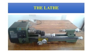
- 1. THE LATHE
- 2. INTRODUCTION • Lathe is one of the oldest important machine tools in the metal working industry. A lathe operates on the principle of a rotating work piece and a fixed cutting tool. • A rope wound round the work with its own end attached to a flexible branch of tree and other end being pulled by man caused job to rotate intermittently. With its further development a strip of wood called “lath” was used to support the rope and that is how the machine came to be known as “lathe”. • The cutting tool is feed into the work piece, which rotates about its own axis, causing the work piece to be formed to the desired shape. • Lathe machine is also known as “the mother/father of the entire tool family.
- 3. HISTORY • The Lathe Machine is one of the oldest and most important machine tools. As early as 1569, wood lathes were in use in France. The lathe machine was adapted to metal cutting in England during the Industrial Revolution. • Lathe machine also called “Engine Lathe” because the first type of lathe was driven by a steam engine.
- 4. INVENTOR OF CENTRE LATHE • Henry Maudsley was born on an isolated farm near Gigghleswick in North Yorkshire and educated at University Collage London. He was an outstandingly brilliant medical student, collecting ten Gold Medals and graduating with an M.D. degree in 1857. • Source :- Internet
- 6. FUNCTION OF THE LATHE The main function of a lathe is to remove metal from a piece of work to give it the required shape and size. Operation Motion of Job Motion of Cutting Tool Turning Rotary Forward translation Boring Forward translation Rotation Drilling Fixed Rotation as well as translator feed Planing Translatory Intermittent translation Milling Translatory Rotation Table 1 :- Nature of Relative Motion For Various Cutting Operations
- 7. • Source :- Internet LATHE PARTS Fig:- Lathe Parts
- 8. Block Diagram of Lathe Fig:- Block Diagram of Lathe • Source :- Internet
- 9. TYPES OF LATHE Lathes of various designs and constructions have been developed to suit the various conditions of metal Machining. But all of them employ the same fundamental principle of operation and perform the same function. The types generally used are: • The Speed Lathe • The Engine Lathe or Centre Lathe • The Bench Lathe • The Capstan and Turret Lathe • Special Purpose Lathe • Automatic Lathe
- 10. This term ‘Engine’ is associated with the lathe owing to the fact that early lathes were driven by steam engine. It is also called center lathe. The most common form of lathe, motor driven and comes in large variety of sizes and shapes. ENGINE LATHE Fig:- Engine Lathe • Source :- Internet
- 11. BENCH LATHE This is a small lathe usually mounted on a bench. It has practically all the parts of an engine lathe or speed lathe And it performs almost all the operations, its only difference being in the size. This is used for small and precision Work. Fig:- Bench Lathe
- 12. A lathe in which the work piece is automatically fed and removed without use of an operator. It requires very less attention after the setup has been made and the machine loaded. AUTOMATIC LATHE Fig:- Automatic Lathe • Source :- Internet
- 13. Distance Between Centres (Radius) One Half of Swing LATHE SIZE AND CAPACITY Fig:- Lathe Size The capacity of a lathe is expressed in two dimensions. The maximum part diameter or swing, and the maximum part Length or distance between centres.
- 14. • This is heavy rugged casting made to support the working parts of lathe and also guide and align major parts of lathe. • Made to support working parts of lathe. • On top section are machined ways. • Guide and align major parts of lathe. Bed is the base of lathe. Bed is made of cast iron . The top of Bed has two guide ways to provide support to the sliding surfaces for the carriage & tail stock. LATHE BED Fig:- Lathe Bed
- 15. Head stock is permanently fastened to the left end of the lathe bed FUNCTION OF HEAD STOCK: To support the spindle To house the main drive SPINDLE: Spindle is the hallow rotating shaft used for holding the work piece HEAD STOCK Fig:- Head Stock
- 16. • Contains number of different-size gears • Provides feed rod and lead-screw with various speeds for turning and thread-cutting operations QUICK CHANGE GEAR BOX Table:- Standard Thread Cutting Gear Values Fig:- Gear Arrangement
- 17. Carriage is located in b/w head stock & tail stock of the lathe bed The carriage travels along the machine’s bed ways, parallel to the It slides along the guide way on the lathe bed. FUNCTION OF CARRIAGE: To hold the cutting tool & give longitudinal or cross feed to the cutting tool. CARRIAGE Fig:- Lathe Carriage
- 18. 1. Saddle: It is a part of the carriage which slides along the guide ways of lathe bed 2. Apron: It is the mechanism of carriage used for manual & mechanized movements of the carriage along longitudinal axis of the lathe 3. Cross- Slide: It is part of carriage which is mounted on saddle. It gives cross feed to the cutting tool 4. Compound Rest: Mounted on top of cross-slide. Can be swiveled to any angle in horizontal plane to facilitate taper turning 5. Tool Post: Mounted on compound rest. It’s function is to hold the cutting tool Parts of Carriage
- 19. TAPER TURNING BY SWIVELLING THE COMPOUND REST This method employs the principle of turning taper by rotating the work piece on the lathe axis and feeding the tool at an angle to the axis of rotation of the work piece. The tool mounted on the compound rest is attached to a circular base, graduated in degree, which may be swivelled and clamped at any desired angle. Taper angle(α) calculated by Where; D= largest diameter. d= Smallest diameter l= length of the tapered portion. Fig:- Swivelling The Compound Rest Arrangement. tanα= 𝐷−𝑑 2𝑙
- 20. • Located at the top of the compound rest. • Hold the tool. • Tool holders are made of different designs according to the shape and purpose of the cutting tool. TOOL POST Fig:- Different Types of Tool Post
- 21. Tail stock is located at the right of the lathe bed. It can be moved along the guide way on the lathe bed & can be clamped at any position on the lathe bed. FUNCTION OF TAIL STOCK: To hold the tool’s like drill, reamer, or tap for cutting operations such as drilling reaming tapping It hold’s dead center which can support the long work pieces during the machining operation. TAIL STOCK Fig:- Tail Stock
- 22. • Work to be turned between centers must have center hole drilled in each end Provides bearing surface • Support during cutting • Care to adjust and lubricate occasionally LATHE CENTERS Fig:- Lathe Centres
- 23. • Used extensively for holding work for machining operations Work large or unusual shape • Most commonly used lathe chucks Three-jaw universal Four-jaw independent Collet chuck Magnetic Chuck CHUKS
- 24. Three jaw Chuck • For holding cylindrical stock centered. • For facing/center drilling etc. Four jaw Chuck This is independent chuck generally has four jaws , which are adjusted individually on the chuck face by means of adjusting screws. Fig:- Chucks • Source :- Internet
- 25. Collet chuck is used to hold small work pieces.Collet Chuck Magnetic Chuck Thin jobs can be held by means of magnetic chucks. Fig:- Chucks • Source :- Internet
- 26. Steady Rest Steady rest is made of cast iron. It may be made to slide on the lathe Bed ways and clamped at any desired position where the workpiece needs support. It has three jaws. These jaws can be adjusted according to the diameter of the work. Machining is done upon the distance starting from the headstock to the point of support of the rest. One or more steady rests may be used to support Work Hinge Jaw Fig:- Steady Rest
- 27. Follower Rest It consists of a ‘C’ like casting having two adjustable jaws to support the workpiece. The rest is bolted to the back end of the carriage. During machining, it supports the work and moves with the carriage. So, it follows the tool to give continuous support to the work to be able to machine along the entire length of the work. In order to reduce friction between the work and the jaws, proper lubricant should be used. Jaw Carriage Work Fig:- Follower Rest