Composite matierals lecture 2
•
2 gefällt mir•1,983 views

Dimensionality of fillers Factors effecting properties of composites Composition of composites By Dr. Mohsin Ali Raza University of the Punjab

Empfohlen
Weitere ähnliche Inhalte
Was ist angesagt?
Was ist angesagt? (20)
Ähnlich wie Composite matierals lecture 2
Ähnlich wie Composite matierals lecture 2 (20)
Mehr von University of the Punjab, Lahore, Pakistan
Mehr von University of the Punjab, Lahore, Pakistan (12)
Kürzlich hochgeladen
Kürzlich hochgeladen (20)
Composite matierals lecture 2
- 1. 18-Apr-16 1 Composite Matierals Dimensionality of fillers Factors effecting properties of composites Composition of composites Dr. Mohsin Ali Raza Dimensionality of the nanofillers
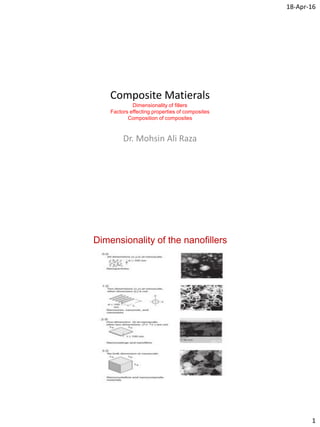
- 2. 18-Apr-16 2 Dimensionality of the nanofillers Morphologies of the nanofillers
- 3. 18-Apr-16 3 Carbon nanoparticles Zero Dimensional Carbon black particles Carbon Nanomaterials
- 4. 18-Apr-16 4 Carbon nanofibres 1-D Carbon nanofibres Carbon nanotubes 1-D Carbon nanotubes
- 5. 18-Apr-16 5 Graphite nanoplatelets/Graphene 2-D Graphite nanoplatelets 2-D nanoclays in a polymer matrix (Intercalated with polymer) (Exfoliated by polymer)
- 7. 18-Apr-16 7 Two very important properties of the fillers • Surface area Smaller particles have higher surface area per unit wt. Interest in nanoparticles generate due to their high surface area. Offers much higher surface for polymer adsorption. Small quantity of nanoparticles can occupy much more volume in the matrix and improved properties can be achieved at lower loading.
- 8. 18-Apr-16 8 Surface to volume ratio • Decreasing particle size increase the surface to volume ratio Surface to volume ratio for a sphere = 𝐴 𝑉 = 3 𝑟 Surface to volume ratio
- 9. 18-Apr-16 9 Surface to volume ratio Ref. S.C. Tjong, H. Chen / Materials Science and Engineering R 45 (2004) 1–88 Surface to volume ratio Ref. S.C. Tjong, H. Chen / Materials Science and Engineering R 45 (2004) 1–88 Effect of Particle size on the melting point of gold
- 10. 18-Apr-16 10 Surface area • Vol. of a particle (10 µm) = 5.23 x 10¹¹ nm3 • Vol. of a particle (10 nm) = 523 nm3 • By diving 10 µm particle into 10 nm particle we get number of particles 𝑎 = 𝑉(10 𝜇𝑚) 𝑉(10 𝑛𝑚) = 5.23 ×10¹¹ 523 = 1 × 10⁹ 𝑝𝑎𝑟𝑡𝑖𝑐𝑙𝑒𝑠 • Surface area of a particle (10 µm) = 3.14 x 10⁸ nm2 • Surface area of a particle (10 nm) = 314 nm2 • Surface area of 1 billion particles = 3.14 x 10¹¹ nm2 Surface area increased by a factor of 1000 Surface area • Surface area of nanoparticles is in the range of 10-500 m2/g or higher • More surface atoms are available for interaction • Measured by N2 adsorption gas studies • Average surface area is reported according to Brauner- Emmer-Teller (BET) analysis
- 11. 18-Apr-16 11 Aspect ratio • Term used for 1 or 2- D fillers • 𝐴 = 𝐿𝑒𝑛𝑔𝑡ℎ 𝐷𝑖𝑎𝑚𝑒𝑡𝑒𝑟 • Fillers with higher aspect ratios lead to much stronger reinforcement • Carbon nanotubes have aspect ratios > 1000. • Higher aspect ratios are required for developing interfiller contacts • Higher aspect ratio filler can serve the purpose at low wt.% loading. Factors on which properties of composites depends • Type of filler and matrix • Concentration or wt.% of the constituents • Size of the filler • Dispersion of the filler • Distribution of the filler • Orientation of the filler • Surface treatment of the filler
- 12. 18-Apr-16 12 Factors on which properties of composites depends Dispersion of the filler in polymer matrix is always a big challenge Effect of concentration on properties of composites
- 13. 18-Apr-16 13 Effect of wt.% or vol.% of filler on the properties of PMC Effect of addition of Vapour grown carbon nanofibres on thermal conductivity of ABS and epoxy polymer Effect of wt.% of filler on ductility of PMC
- 14. 18-Apr-16 14 Effect of wt.% of filler on Flexural modulus of PMC Effect of wt.% of filler on Notched Impact Strength of PMC
- 15. 18-Apr-16 15 TEM images to judge dispersion of the nanoparticles Does the strength keeps on increasing with the loading of fillers?
- 16. 18-Apr-16 16 Does the strength keeps on increasing with the loading of fillers? At high loading, Nanofillers tend to agglomerate more Enhancement of modulus by the addition of nanoclays
- 17. 18-Apr-16 17 Increase in electrical conductivity with increase of filler loading C A R B O N 50 ( 2 01 2 ) 84 – 9 7 Electrical conductivity of VGCNF/epoxy composites Size of fillers
- 18. 18-Apr-16 18 Comparison of micro and nanosized filler Distribution/Dispersion of fillers
- 19. 18-Apr-16 19 Effect of distribution and dispersion on the electrical conductivity of polymer composites Distribution and dispersion of carbon nanofibres in epoxy Agglomerates C A R B O N 50 ( 2 01 2 ) 84 – 9 7
- 20. 18-Apr-16 20 Orientation of fillers Effect of alignment of carbon nanotube on the thermal conductivity of carbon nanotube/epoxy composites
- 21. 18-Apr-16 21 Shape of the filler/dimensionality of filler Production of Nylon-Mica composites Ref. http://www.imp.mtu.edu/jmmce/issue3-1/P31_3.pdf Ball milling
- 22. 18-Apr-16 22 Properties of Graphene and Carbon nanotube composites Effect of Dimensionality of Filler on Barrier properties Ref: C A R B O N 5 0 ( 2 0 1 2 ) 1 1 3 5 – 1 1 4 5
- 23. 18-Apr-16 23
- 24. 18-Apr-16 24 Composition of composites • Volume fraction of constituents 𝑉𝑐 = 𝑣𝑓 + 𝑣 𝑚 𝑉𝑜𝑙𝑢𝑚𝑒 𝑓𝑟𝑎𝑐𝑡𝑖𝑜𝑛 𝑜𝑓 𝑓𝑖𝑏𝑟𝑒 = 𝑉𝑓 = 𝑣𝑓 𝑉𝑐 𝑉𝑜𝑙𝑢𝑚𝑒 𝑓𝑟𝑎𝑐𝑡𝑖𝑜𝑛 𝑜𝑓 𝑚𝑎𝑡𝑟𝑖𝑥 = 𝑉𝑚 = 𝑣 𝑚 𝑉𝑐 𝑉𝑓 + 𝑉𝑚 = 1 Composition of composites • Mass fraction of constituents 𝑊𝑐 = 𝑚 𝑓 + 𝑚 𝑚 𝑀𝑎𝑠𝑠 𝑓𝑟𝑎𝑐𝑡𝑖𝑜𝑛 𝑜𝑓 𝑓𝑖𝑏𝑟𝑒 = 𝑊𝑓 = 𝑚 𝑓 𝑊𝑐 𝑀𝑎𝑠𝑠 𝑓𝑟𝑎𝑐𝑡𝑖𝑜𝑛 𝑜𝑓 𝑚𝑎𝑡𝑟𝑖𝑥 = 𝑊𝑚 = 𝑚 𝑚 𝑊𝑐 𝑊𝑓 + 𝑊𝑚 = 1
- 25. 18-Apr-16 25 Relationship between volume fraction and mass fraction 𝐷𝑒𝑛𝑠𝑖𝑡𝑦 𝑜𝑓 𝑐𝑜𝑚𝑝𝑜𝑠𝑖𝑡𝑒 = 𝜌 𝑐 = 𝑊𝑐 𝑉𝑐 𝑀𝑎𝑠𝑠 𝑜𝑓 𝑐𝑜𝑚𝑝𝑜𝑠𝑖𝑡𝑒 = 𝑊𝑐 = 𝜌 𝑐 𝑉𝑐 (1) 𝐷𝑒𝑛𝑠𝑖𝑡𝑦 𝑜𝑓 𝑀𝑎𝑡𝑟𝑖𝑥 = 𝜌 𝑚 = 𝑚 𝑚 𝑣 𝑚 𝑀𝑎𝑠𝑠 𝑜𝑓 𝑀𝑎𝑡𝑟𝑖𝑥 = 𝑚 𝑚 = 𝜌 𝑚 𝑣 𝑚 (2) 𝐷𝑒𝑛𝑠𝑖𝑡𝑦 𝑜𝑓 𝑓𝑖𝑏𝑟𝑒 = 𝜌 𝑓 = 𝑚 𝑓 𝑣𝑓 𝑀𝑎𝑠𝑠 𝑜𝑓 𝑓𝑖𝑏𝑟𝑒 = 𝑚 𝑓 = 𝜌 𝑓 𝑣𝑓 (3) Relationship between volume fraction and mass fraction From Eq (1) and (2) (dividing 2 by 1) 𝑚 𝑚 𝑊𝑐 = 𝜌 𝑚 𝑣 𝑚 𝜌 𝑐 𝑉𝑐 (A) 𝑣 𝑚 𝑉𝑐 = 𝑣𝑜𝑙 𝑓𝑟𝑎𝑐𝑡𝑖𝑜𝑛 𝑜𝑓 𝑚𝑎𝑡𝑟𝑖𝑥 = 𝑉𝑚 𝑚 𝑚 𝑊𝑐 = 𝑣𝑜𝑙 𝑓𝑟𝑎𝑐𝑡𝑖𝑜𝑛 𝑜𝑓 𝑚𝑎𝑡𝑟𝑖𝑥 = 𝑊𝑚 Eq. (A) becomes 𝑊𝑚 = 𝜌 𝑚 𝜌 𝑐 𝑉𝑚 (B) Similarly from 1 and 3 we get, 𝑊𝑓 = 𝜌 𝑓 𝜌 𝑐 𝑉𝑓 (C)
- 26. 18-Apr-16 26 Rule of mixture The properties of composite material depend on the relative quantities and properties of its constituents. 𝑃𝐶𝑀 = 𝑓𝑖 𝑝𝑖 PCM = Properties of composite material fi= volume fraction of each 𝑖 , 𝑓𝑖=1 Density of composite in terms of volume fraction 𝑊𝑐 = 𝑊𝑚 + 𝑊𝑓 𝜌𝑐 𝑉𝑐 = 𝜌 𝑚 𝑣 𝑚 + 𝜌 𝑓 𝑣𝑓 𝜌𝑐 = 𝜌 𝑚 𝑣 𝑚 𝑉𝑐 + 𝜌 𝑓 𝑣𝑓 𝑉𝑐 Density of composite 𝜌𝑐 = 𝜌 𝑚 𝑉𝑚 + 𝜌 𝑓 𝑉𝑓 (D)
- 27. 18-Apr-16 27 Relationship between volume fraction and mass fraction Eq. (A) becomes 𝑊𝑚 = 𝜌 𝑚 𝜌 𝑐 𝑉𝑚 (B) 𝑊𝑚 = 𝜌 𝑚 𝜌 𝑚 𝑉𝑚 + 𝜌 𝑓 𝑉𝑓 𝑉𝑚 Similarly from 1 and 3 we get, 𝑊𝑓 = 𝜌 𝑓 𝜌 𝑐 𝑉𝑓 (C) 𝑊𝑓 = 𝜌 𝑚 𝜌 𝑚 𝑉𝑚 + 𝜌 𝑓 𝑉𝑓 𝑉𝑚 Relationship between volume fraction and mass fraction of composite constituents From Eq. (A) 𝑊𝑚 = 𝜌 𝑚 𝜌𝑐 𝑉𝑚 Putting value of ρc 𝑊𝑚 = 𝜌 𝑚 𝜌 𝑚 𝑉𝑚 + 𝜌 𝑓 𝑉𝑓 𝑉𝑚 Dividing and multiplying by ρm 𝑊𝑚 = 1 𝜌 𝑓 𝜌 𝑚 1−𝑉 𝑚 +𝑉𝑚 𝑉𝑚 Note 𝑉𝑓 = 1 − 𝑉𝑚 Also, 𝑊𝑓 = 𝜌 𝑓 𝜌 𝑚 𝜌 𝑓 𝜌 𝑚 𝑉 𝑓+𝑉 𝑚 𝑉𝑓
- 28. 18-Apr-16 28 Relationship between volume fraction and mass fraction of composite constituents Prove the relation between volume fraction of fibres to that of mass fraction and densities of fibres and matrix. i.e, Vm = ? Actual volume of a Composite 𝑉𝑐 = 𝑉𝑓 + 𝑉𝑚 + 𝑉𝑣𝑜𝑖𝑑𝑠 (E) Exp. Density of a composite 𝜌𝑐𝑒 = 𝑊𝑐 𝑉𝑐 (Actual density of a composite) 𝑉𝑐 = 𝑊𝑐 𝜌 𝑐𝑒 substitute in Eq (E) 𝑊𝑐 𝜌 𝑐𝑒 = 𝑉𝑚 + 𝑉𝑓 + 𝑉𝑣𝑜𝑖𝑑𝑠 (F)
- 29. 18-Apr-16 29 Theoretical density of a composite 𝑇ℎ𝑒𝑜𝑟𝑒𝑡𝑖𝑐𝑎𝑙 𝑑𝑒𝑛𝑠𝑖𝑡𝑦 = 𝑀𝑎𝑠𝑠 𝑜𝑓 𝑐𝑜𝑚𝑝𝑜𝑠𝑖𝑡𝑒 𝑇ℎ𝑒𝑜𝑟𝑒𝑡𝑖𝑐𝑎𝑙 𝑣𝑜𝑙. 𝑜𝑓 𝑐𝑜𝑚𝑝𝑜𝑠𝑖𝑡𝑒 𝜌 𝑐𝑡 = 𝑊𝑐 𝑉𝑐𝑡 Or 𝑉𝑐𝑡 = 𝑊𝑐 𝜌 𝑐𝑡 Since theoretical vol. of a composite = Vol. of matrix + Vol. of fibre 𝑉𝑐𝑡 = 𝑉𝑚 + 𝑉𝑓 𝑊𝑐 𝜌𝑐𝑡 = 𝑉𝑚 + 𝑉𝑓 Substituting value of "𝑉𝑚 + 𝑉𝑓”in Eq. (F) Volume fraction of Voids 𝑊𝑐 𝜌 𝑐𝑒 = 𝑊𝑐 𝜌 𝑐𝑡 + 𝑉𝑣𝑜𝑖𝑑𝑠 𝑉𝑣𝑜𝑖𝑑𝑠 = 𝑊𝑐 𝜌 𝑐𝑒 − 𝑊𝑐 𝜌 𝑐𝑡 𝑉𝑣𝑜𝑖𝑑𝑠 = 𝑊𝑐 1 𝜌 𝑐𝑒 − 1 𝜌 𝑐𝑡 𝑉𝑣𝑜𝑖𝑑𝑠 = 𝑊𝑐 𝜌 𝑐𝑒 𝜌 𝑐𝑡 − 𝜌 𝑐𝑒 𝜌 𝑐𝑡 Since 𝑊𝑐 𝜌 𝑐𝑒 = 𝑉𝑐 𝑉𝑣𝑜𝑖𝑑𝑠 = 𝜌 𝑐𝑡−𝜌 𝑐𝑒 𝜌 𝑐𝑡 This is fractional volume of voids present in the composite.
- 30. 18-Apr-16 30 Problem Determine the density of glass fibre/epoxy composite with a 70% fibre vol. fraction. Also determine the mass fractions of the fibre. The density of fibre and matrix is 2500 and 1200 kg/m3, respectively. 𝜌𝑐 = 𝜌 𝑚 𝑉𝑚 + 𝜌 𝑓 𝑉𝑓 𝜌𝑐 = 2110 𝑘𝑔/𝑚3 Using , 𝑊𝑚 = 𝜌 𝑚 𝜌 𝑐 𝑉𝑚 and 𝑊𝑓 = 𝜌 𝑓 𝜌 𝑐 𝑉𝑓 𝑊𝑓 = 0.8294 𝑊𝑚 = 0.1706 Home work Problem Calculate the amount of epoxy resin, curing agent and carbon black to produce a 50 cm3 sample of carbon black/epoxy composite at carbon black wt.% 10-90 (with increments of 10 %). Also report volume fraction of resin and carbon black. Make a table of data in excel and show with the calculations. You are provided following data: Density of curing agent = 0.991 g/cm3 Density of Epoxy resin = 1.16 g/cm3 Density of Carbon black = 2.26 g/cm3 Vol. of the composite to be fabricated = 50 cm3 The ratio of curing agent/Epoxy resin by weight = 75/25
- 31. 18-Apr-16 31 Home work Problem Calculate the amount of epoxy resin, curing agent, carbon black and carbon fibres to produce a 50 cm3 sample of carbon black/carbon fibre/epoxy composite at total content of carbon black and carbon fibres wt.% 10-90 (with increments of 10 %). Assume each composite composition has carbon black and carbonf fibres in the ratio of 1:2. Also report volume fraction of resin, carbon black and carbon fibre. Make a table of data in excel and show with the calculations. You are provided following data: Density of curing agent = 0.991 g/cm3 Density of Epoxy resin = 1.16 g/cm3 Density of Carbon black = 2.26 g/cm3 Vol. of the composite to be fabricated = 50 cm3 The ratio of curing agent/Epoxy resin by weight = 75/25 Fibre reinforced Composites • Fibres are reinforced in the matrix Fibres can be micro or nanofibres • Most important class of composites for structural applications • Important characteristics are specific strength and modulus (offers high strength to weight ratio) • Utilises the low density of fibres and matrix to produce high strength composites
- 32. 18-Apr-16 32 Why fibres for reinforcement? The most common geometrical shape used for reinforcement Fibres have fewer flaws than bulk materials Real strength of materials is always lower than the theoretical Strength The strength of brittle materials is inversely proportional to the square root of its max flaw size 𝜎 ∝ 1 𝑎 Where a = max. crack length and σ is strength Decreasing diameter increases strength of fibres • As the area decreases, strength increases
- 33. 18-Apr-16 33 Production of fibres result in orientation of molecules Fibre strength can be increased by orienting the fibre axis along the direction of the strong covalent bonds Graphite planes oriented in graphite fibres Graphite Increasing the degree of orientation increases strength Fibres offer higher fibre-matrix interface for maximising strength and toughness Area of fibre-matrix interface is inversely proportional to the diameter of the fibres. Small fibre-matrix interface area large fibre-matrix interface area
- 34. 18-Apr-16 34 Fibres offer higher fibre-matrix interface for maximising strength and toughness For fixed fibre volume in a given volume of composite, the area of the fibre-matrix interface is inversely proportional to the diameter of the fibres Flexibility of fibres • Smaller the diameter, higher will be flexibility of fibres • Fibres made from brittle materials are highly flexible • Bending stiffness of fibre is inversely proportional to flexibility Bending stiffness = EI The minor decrease in fibre diameter can result in an enormous decrease in bending stiffness or increase in flexibility Decreasing fibre diameter, increases modulus, strength and flexibility
- 35. 18-Apr-16 35 Problem Flexible nylon fibres with E= 3 GPa and dia of 25 µm can be easily wound on spools. What must be the diameter of the following fibres (which have circular cross-section) to show the same flexibility? A. SiC B. Pitch-based C fibres C. Kevlar- 49 D. Boron E for SiC = 430 Gpa EI (nylon) = EI (SiC) 3 × 𝜋 254 64 = 430 × 𝜋𝑑4 64 d (SiC) = 7.2 µm d(pitch based C fibre) = 9.5 µm d(kevlar) = 9.7 µm d (boron) = 7.3 µm Flexural strength vs diameter of fibres
- 36. 18-Apr-16 36 Mechanical Properties of reinforcing fibres Typical fiber diameters are from 1 µm to 150 µm Functions of fibres • To carry load (ca. 70 to 90 % load is carried by fibres in a composite) • Fibres provide stiffness (rigidity), strength and structural properties to the composite • Fibres can also provide electrical conduction, thermal conduction or insulation properties depending on the requirement and type of the fibre used Attractive fibres for composite reinforcement must have high strength and high elastic modulus. They must also be suitable for production in small diameters. Popular fibres: glass fibres, carbon fibres, graphite fibres, aramid fibres, SiC fibres, etc.
- 37. 18-Apr-16 37 Influence of fibre length on the properties of composites • Strong fibres are embedded in a softer matrix to produce products with high strength-to-weight ratios • The matrix transmits the load to the fibres • Interfacial bond between the fibre and matrix determines how much load will be transmitted to the fibres Fibre-matrix bond ceases at the extremities of the fibre All load transfers to matrix Fibre carrying most of load Critical length of fibre • Critical length of fibre mandatory for maximum reinforcement 𝑙 𝑐 = 𝜎𝑓 𝑑 2𝜏 𝑐 𝑙 𝑐= critical length d= diameter of fibre 𝜎𝑓= tensile strength of fibre 𝜏 𝑐= fibre-matrix bond strength (shear yield strength of the matrix) Critical length of glass and carbon fibre-matrix combinations is ca. 1 mm , this is 20 to 150 x fibre diameter Long fibers are preferred because the ends of the fiber carry less of the load. Thus the longer the fiber, the fewer the ends and the higher the load carrying capacity of the fibers
- 38. 18-Apr-16 38 Strength of composite increases as length of fibre increases Strength of E-Glass/epoxy composite Stress-position profiles for fibres To achieve maximum reinforcement from fibres, continuous fibres must be used
- 39. 18-Apr-16 39 Classification of fibre reinforced composites on the basis of length of fibres Classification according to Length of fibres l>>lc (l>15lc) l>>lc (lc<l<15lc)
- 40. 18-Apr-16 40 Influence of reinforcement type and quality on composite performance Mechanical Properties of fibre, matrix and composite
- 41. 18-Apr-16 41 Stress-strain behaviour of aligned fibre reinforced composite High potential to be used as nanofiller for producing high strength, high electrically and thermally conducting composites.
- 42. 18-Apr-16 42 Continuous and aligned fibre reinforced composites • Lf> 15 Lc • Usually fibres are very much long and present in the matrix without any discontinuity • Properties of these composite are highly anisotropic • Excellent mechanical properties in the direction of fibres but poor in transverse direction Transverse direction Longitudinal direction Modulus of elasticity of continuous and aligned composites • Modulus of elasticity can be theoretically estimated for such composites using rule of mixture Assumptions Fibre-matrix interfacial bond is ideally good The deformation of the matrix and fibre in longitudinal direction i.e, strain in Matrix and Fibre is same (Iso-strain condition)
- 43. 18-Apr-16 43 Modulus in longitudinal direction of aligned fibre reinforced composites • Iso-Strain condition The total load sustained by the composite is 𝐹𝑐 = 𝐹 𝑚 + 𝐹𝑓 (i) 𝐹 = 𝜎𝐴 Eq (i) becomes 𝜎𝑐 𝐴 𝑐 = 𝜎 𝑚 𝐴 𝑚 + 𝜎𝑓 𝐴 𝑓 𝜎𝑐 = 𝜎 𝑚 𝐴 𝑚 𝐴 𝑐 + 𝜎𝑓 𝐴 𝑓 𝐴 𝑐 (ii) Assumption: Length of fibre and matrix are equal 𝑉𝑚 = 𝐴 𝑚 𝐴 𝑐 and 𝑉𝑓 = 𝐴 𝑓 𝐴 𝑐 Eq. (ii) becomes 𝜎𝑐 = 𝜎 𝑚 𝑉𝑚 + 𝜎𝑓 𝑉𝑓 (iii) Modulus in longitudinal direction of aligned fibre reinforced composites Under Iso-strain condition 𝜖 𝑐 = 𝜖 𝑚 = 𝜖 𝑓 Dividing Eq (iii) by respective strains Furthermore, 𝜎 𝑐 𝜖 𝑐 = 𝐸𝑐 , 𝜎 𝑚 𝜖 𝑚 = 𝐸 𝑚, 𝜎 𝑓 𝜖 𝑓 = 𝐸𝑓 Eq. (iv) becomes 𝐸𝑐𝐿 = 𝐸 𝑚 𝑉𝑚 + 𝐸𝑓 𝑉𝑓 (v) or 𝐸𝑐𝐿 = 𝐸 𝑚(1 − 𝑉𝑓) + 𝐸𝑓 𝑉𝑓 𝜎 𝑐 𝜖 𝑐 = 𝜎 𝑚 𝜖 𝑚 𝑉𝑚 + 𝜎 𝑓 𝜖 𝑓 𝑉𝑓 (iv) Modulus of Elasticity of aligned fibre reinforced composite in longitudinal direction is equal to volume fraction weighted average of the modulii of elasticity of the fibre and matrix phases
- 44. 18-Apr-16 44 Tensile strength and coefficient of thermal expansion of aligned fibre reinforced composite Tensile strength in longitudinal direction 𝑈𝑇𝑆 𝑐𝐿 = 𝑈𝑇𝑆 𝑚 𝑉𝑚 + 𝑈𝑇𝑆𝑓 𝑉𝑓 Coefficient of thermal expansion 𝛼 𝑐𝐿 = 𝛼 𝑚 𝑉𝑚 + 𝛼 𝑓 𝑉𝑓 Modulus in Transverse direction of aligned fibre reinforced composites When load is applied perpendicular to the direction of the fibres; for such case stress to which composite as well as both phases are exposed is the same Under Iso-stress condition 𝜎𝑐 = 𝜎 𝑚 = 𝜎𝑓 The strain of the entire composite would be 𝜖 𝑐 = 𝜖 𝑚 𝑉𝑚 + 𝜖 𝑓 𝑉𝑓 (vi) since 𝜖 = 𝜎 𝐸 Eq. (vi) becomes 𝜎 𝐸𝑐 = 𝜎 𝐸 𝑚 𝑉𝑚 + 𝜎 𝐸𝑓 𝑉𝑓 or 𝐸𝑐𝑇 = 𝐸 𝑚 𝐸 𝑓 𝑉 𝑚 𝐸 𝑓+𝑉 𝑓 𝐸 𝑚 (vii)
- 45. 18-Apr-16 45 Example Problem A continuous and aligned fibre-reinforced composite is to be produced consisting of 45 vol.% aramid fibres and 55 % vol. of a polycarbonate matrix. Mechanical characteristics of these two are as follows: phase M.E (psi) T.S (psi) Aramid fibre 19 x 106 500,000 Poly carbonate 3.5 x 10⁶ 8000 For this composite compute (a) the longitudinal tensile strength (b) longitudinal modulus of elasticity. 𝐸𝑐𝐿 = 𝐸 𝑚 𝑉𝑚 + 𝐸𝑓 𝑉𝑓 𝑈𝑇𝑆 𝑐𝐿 = 𝑈𝑇𝑆 𝑚 𝑉𝑚 + 𝑈𝑇𝑆𝑓 𝑉𝑓 Discontinuous fibre composites • Lf < 15Lc • Can be aligned or randomly oriented • When fibre length is less than Lc, the matrix deforms around the fibre such that there is virtually no stress transference and little reinforcement by the fibres. Such composites come in the category of particulate composites. • Discontinuous and aligned fibre composite although have lower reinforcement efficiency, they are becoming more important in commercial market. • Chopped glass fibres are extensively used to produce discontinuous fibre reinforced composites. Their modulus and tensile strength approach 90% and 50 % respectively of their continuous fibre counterparts.
- 46. 18-Apr-16 46 Fibre reinforcement efficiency parameter (η) • The properties of discontinuous and aligned fibre reinforced composites depend on η which itself depends on the length of fibres. 𝜂 = 1 − 𝐿 𝑐 2𝐿 Tensile strength of discontinuous and aligned fibre reinforced composites • When L>Lc , tensile strength in longitudinal direction is given by • When L<Lc, tensile strength is given by
- 47. 18-Apr-16 47 Tensile strength of discontinuous and randomly oriented fibre reinforced composites • For these composites reinforcement efficiency parameter depends on volume fraction of fibres and the ratio of Ef and Em. • Elastic modulus of such composites according to rule of mixture can be given as 𝐸𝑐𝑑 = 𝐾𝐸𝑓 𝑉𝑓 + 𝐸 𝑚 𝑉𝑚 Where K is reinforcement efficiency parameter Practice problems Solve the problems 17.10-17.22 of Chapter 17 from Book Materials Science and Engineering An Introduction by W. D. Callister (5th edition) Or problems 16.1 to 16.21 (8th Edition)
- 48. 18-Apr-16 48
- 49. 18-Apr-16 49 Read full story at the link provided
- 50. 18-Apr-16 50
- 51. 18-Apr-16 51 Fibre reinforced polymer matrix composites • Polymer is used as matrix and fibres can continuous, discontinuous (aligned or randomly oriented) • Matrix can be thermoplastic (nylon 6,6, polycarbonate, PET, etc are used) or thermosetting (epoxy, polyester (unsaturated) • Commonly used fibres are Glass fibres Aramid fibres (Kevlar) Carbon fibres
- 52. 18-Apr-16 52 Glass fibre reinforced polymer composites • Glass fibres can be continuous or discontinuous • Most widely used composite and have wide range of applications Types of glass fibres i. E-glass (Electrical glass): Lime-aluminium boro silicate glass with zero or low sodium and potassium levels. Composition of E-glass: 52-56% SiO2, 12-16% Al2O3, 16-25 % CaO and 8-13% B2O3 ii. S-glass (high strength): Have high strength to weight ratio. More expensive than E-glass and is used primarily for military and aerospace applications. Composition of S-glass: 65% SiO2, 25%Al2O3, 10 % MgO Diameter of glass fibre ranges from 3-20 µm Comparison of strength of S- and E-glass fibres Specific gravity of glass fibres is 2.5 which is very much higher than carbon and aramid fibres (1.8 and 1.4 ,respectively)
- 53. 18-Apr-16 53 Why glass fibres are most popular reinforcement material? • It can be easily drawn into fibres from molten state. Continuous variation of glass viscosity with temperature and the high surface tension favours the formation of fibres. • It is readily available and low cost because its raw material is relatively cheap. • Available in the form of various fibre architectures or mats (like woven cloth) • Can be easily reinforced by different composite fabrication techniques • As a fibre, it is relatively very strong and when embedded in polymer matrix, it produces a composite having very high specific strength • When coupled with various polymers it possesses a chemical inertness that make composite very useful for a variety of corrosive environments. Fiberizing/Production of glass fibres Production of continuous filament of glass fibres Batching Melting (1700 ᵒC) Fiberisation Sizing/coating Drying and packaging http://www.compositesworld.com/articles/the-making-of-glass-fiber 250 Platinum alloy nozzles of dia 10 µm Drawing speed 25 m/s Strand has 200 filaments
- 54. 18-Apr-16 54 Fiberizing/Production of glass fibres Production of discontinuous filament of glass fibres Chopped glass fibres Rovings Woven fabric Emulsion mats Needled mats Size formulations
- 55. 18-Apr-16 55 Surface characteristics of glass fibres • Surface characteristics of glass fibres are extremely important because even few surface flaws have deleterious effect on mechanical properties. • Surface flaws can be easily introduced by rubbing and abrading the surface with another hard material. • Newly drawn fibres are coated during drawing with a “size” a thin layer of a substance that protects the fibre surface from damage and undesirable environmental interactions. • The size is usually removed before composite fabrication and replaced with “coupling agent” or finish that provides better bond between the fibre and matrix. Silane compounds are most commonly used as coupling agents. What is fibre glass? It is technical term applied to products or composites made from glass fibres Disadvantages of fibre glass Lack rigidity which is required for example for structural members for air planes and bridges. Limited service temperature (below 200 ºC). Applications of fibre glass Automotive and marine bodies, pipes, storage containers, industrial flooring, roofing, lining for electroplating vats, sports goods, boats.
- 56. 18-Apr-16 56 SEM images of fibreglass-reinforced composites Interfaces in glass fibre/polymer composites • Stronger interfaces between the fibre and matrix ensures the maximum reinforcement and enhanced mechanical properties. • Stability and durability of interfacial region is primary issue because the environmental effects such as temperature, moisture and stresses can degrade the interfacial bonding. • Highly hygroscopic nature of unprotected glass fibres can result in poor adhesion. (drying of fibres is essential) • Unprotected and unbonded fibres can break at relatively low loads and have enough stored elastic energy lost at the ends of fibres which can propagate cracks in the matrix or along the fibre/matrix interface (every end of fibres is source of stress concentration)
- 57. 18-Apr-16 57 Interfaces in glass fibre/polymer composites • Strength/bonding of polymer adsorbed on glass fibre depends on the intermolecular forces of attraction at the interfaces. • In the absence of primary chemical bonding then there should be secondary bonding (Vander Waals forces or polar bonding) • The adsorption of polymer molecule on the surface (glass fibre) decrease the mobility of the molecule but primary modes of translational, rotational and vibration still remain present. • Foreign molecules like water can still penetrate at the interface and replace the polymer chain segments Glass fibre composites performance degrade under wet condition because of loss of interfacial bonding and decrease in tensile strength of the reinforcing fibres Interfaces in glass fibre/polymer composites
- 58. 18-Apr-16 58 Silane coupling agents for glass fibre/polymer composites • Organofunctional silanes are the most widely used for improvement of interfacial adhesion in glass fibre reinforced composites • The effectiveness of silane treatment depends on: o Nature and pretreatment of the substrate o Type of silane used o Thickness of the silane layer o Application process o Nature of chemical bond between constituents Reaction and bonding of alkoxysilane with substrate Materials Science and Engineering A302 (2001) 74–82
- 59. 18-Apr-16 59 Reaction and bonding of alkoxysilane with substrate M.M. Kabir et al. / Composites: Part B 43 (2012) 2883–2892 Changing matrix by diffusion of siloxane Polymer/siloxane/glass interface
- 60. 18-Apr-16 60 Carbon fibre-reinforced polymer composites What is a carbon fibre? Carbon fibres have a highly distorted and defective graphite-like structure. Carbon fibres are produced so that the fibre axis lies in the basal plane, along the direction of the strong covalent bonds. Elastic modulus along the fibre axis can be as high as 1000 GPa but in transverse direction can be as low as 35 GPa. The mechanical, chemical, electrical and other physical properties depends on the raw material and processing treatment. • Carbon fibres are reinforced in polymer matrix • Commonly used polymer matrix is thermosetting epoxy or PEEK Precursor for carbon fibres Carbon fibres can be fabricated from three precursors (i) Polyacrylonitrile (PAN) (ii) Pitch (iii) Rayon, PVC
- 61. 18-Apr-16 61 Types of carbon fibres • On the basis of production techniques carbon fibres can be divided into two major types (i) High strength carbon fibres (ii) High modulus carbon fibres • Carbon fibres on commercial scale are made from Pitch (pitch is converted into liquid crystalline material (mesophase) and melt spun into fibres and then pyrolysed. Produced from PAN fibres Production of Carbon fibres Three stages of Production from PAN fibres Stabilisation Carbonisation Graphitisation
- 62. 18-Apr-16 62 Production of Carbon fibres A carbonisation process then follows in huge furnaces, where all non-carbon molecules are removed while the chemical properties of the remaining carbon molecules are changed to help them bond better, thus making the carbon strong. Production of Carbon fibres
- 63. 18-Apr-16 63 Production of Carbon fibres 800-1500 ᵒC No air Oxidisation 1500-2000 ᵒC No air High strength carbon fibres High modulus carbon fibres http://www.arrhenius.ucsd.edu/miakel/Miakel_B.html Stretching ensures perfect crystal orientation Modulus after graphitisation reaches 300- 600 GPa Production of Carbon fibres
- 64. 18-Apr-16 64 SEM images of carbon fibres produced from PAN and pitch SEM micrographs of the transverse sections for carbon fibers: (a) PAN-13; (b) PAN-27; (c) MPP-13; (d) Enlarged MPP-13;(e) MPP-27; (f) Enlarged MPP-27. C A R B O N 5 0 ( 2 0 1 2 ) 4 4 5 9 – 4 4 6 9 4463 Formation of Carbon fibres http://www.sciencedirect.com/science/article/pii/S0008622312004538
- 65. 18-Apr-16 65 TEM images of Carbon fibres TEM micrographs of the transverse sections: (a) PAN-13; (b) PAN-20; (c) PAN-25; (d) PAN-27; (e) MPP-13; (f) MPP-20; (g)MPP-25; (h) MPP-27. Effect of heat treatment on mechanical properties of carbon fibres
- 66. 18-Apr-16 66 Elemental analysis and diameters of carbon fibres produced by heat treatment at various temperatures C A R B O N 5 0 ( 2 0 1 2 ) 4 4 5 9 – 4 4 6 9 4463 Properties of Carbon fibres • Advantages – Low density (1.8-2.2 g/cm3) – High tensile modulus and strength up to 2000 ºC (non- oxidizing environment) – Resistant to creep – High fracture toughness – Low coefficient of thermal expansion – High thermal conductivity • Thus, thermal shock is relatively unimportant • Disadvantages – High temperature oxidation – Very expensive – Complex and low volume processing/manufacturing
- 67. 18-Apr-16 67 Carbon-Carbon composites • Carbon fibres and carbon matrix • These materials are relatively new and expensive and, therefore, are not currently being utilized extensively. • Their desirable properties include high-tensile moduli and tensile strengths that are retained even at high temperatures, resistance to creep, and relatively large fracture toughness values. • Carbon–carbon composites have low coefficients of thermal expansion and relatively high thermal conductivities; these characteristics, coupled with high strengths, give rise to a relatively low susceptibility to thermal shock. Their major drawback is a propensity to high temperature oxidation. Applications: For space structures , sports equipment, biomedical application (body implants) Carbon fibre architecture Carbon fibres are used in 2-D or 3-D architecture to increase the off-axis strength
- 68. 18-Apr-16 68 Production of carbon matrix composites • Carbonization, followed by impregnation of pitch or resin, and repeating the carbonization-impregnation process again and again until sufficient density has been attained. • Chemical vapor infiltration (CVI) using a carbonaceous gas, i.e., CVD under a temperature/pressure gradient so as to prevent crust formation, thereby allowing complete infiltration; CVD can be an extra step that follows carbonization- impregnation for the purpose of filling the pores.
- 69. 18-Apr-16 69 Flow sheet diagram for production of carbon matrix composites Carbon fibre preform structure Liquid impregnation (phenol, furfural or pitch) Chemical vapour deposition (hydrocarbon gas) 1000-2000 ᵒC Carbonisation 1000-1200 ᵒC Heat treatment 2000-2800 ᵒC C-C composite 1-5 times 1-3 times Aramid Fibre reinforced Polymer Composites Aramid fibres are reinforced in polymer matrix Aramid is generic name for aromatic polyamide fibres The chemical repeating unit of aramid polymer chain is that of a aromatic polyamide. This group of material is known as poly paraphenylene terephthalamide. Aramid structure
- 70. 18-Apr-16 70 Production of Aramid Fibres Aramid fibres are produced by solution- polycondensation of diamines and diacid halides at low temperature. Diacid chloride is rapidly added to a cool (5-10 °C) amine solution while stirring. The polymer formed is recovered from crumbs or gels by pulverising, washing and drying. To form filaments, the clean polymer, mixed with a strong acid (H2SO4), is extruded from spinnerets at an elevated temperature (50-100 °C) through a 0.5-1.9 cm layer of air into cold water (0-4 °C). The fibres are then washed thoroughly in water and dried on bobbins. Production of Aramid Fibres Nomex Kevlar
- 71. 18-Apr-16 71 Structure of Aramid Fibres Properties of Aramid fibres Good resistance to abrasion Non conductive No melting point, high degradation temperature 500 ºC Low flammability Hydrophilicity due to amide linkage, high water absorption (fibre structure plays an important role in moisture absorption) Good fabric integrity at elevated temperature Sensitive to ultraviolet radiation Prone to static-build of charges 20 times higher specific strength than steel Very low density (1.4 g/cm3) Poor under compression Suffers corrosion in chlorine atmosphere Strong acids attack at higher temperature Difficult to dye due to their high Tg
- 72. 18-Apr-16 72 Comparison of Properties of Aramid fibres with other fibres ©2003Brooks/Cole,adivisionofThomsonLearning,Inc.ThomsonLearning™isatrademarkusedhereinunderlicense. Types of Aramid fibres Kevlar 29 – Reinforcement for car and cycle tyres (reduces puncture rates) – Standard type is more expensive than that used in tyres and this is used for body armour for light weight military vehicles, bullet proof helmets and vests. Kevlar 49 – Light weight and can withstand considerable force (twisting, torque, tensile, impact) – Used for boat hulls and in aerospace industry
- 73. 18-Apr-16 73 Effect of addition of aramid on wear rates of polyamide 6,6 Applications of Fibre reinforced Composites
- 74. 18-Apr-16 74 Applications of Fibre reinforced Composites Applications of Fibre reinforced Composites
- 75. 18-Apr-16 75 Processing of Fibre-Reinforced Composites Open moulding processes • Hand lay-up process • Spray-up • Vacuum bag autoclave moulding • Pressure bag moulding • Autoclave moulding Continuous/semi automatic processes Pultrusion Prepreg/Sheet moulding compound production Filament winding Close moulding • Compression moulding • Injection moulding • Resin Transfer moulding or VARTM Hand lay-up • Commonly used for production of DCFRC • Fibres in the form of mats (discontinues fibres) are used • Parts of any shape or dimension and surface area of few square feet can be produced by this method • Easy method • Resins used: epoxy, polyester, phenolic, vinylester • Fibres used: any in the form of mats or stitched into a fabric form • Applications: Aircraft component parts, boat hulls, bumpers, wind turbine blades, tanks, etc.
- 76. 18-Apr-16 76 Spray-up process • Low cost method of quickly depositing fibre and matrix • Glass fibre rovings are only used • Parts of any shape or dimension and very large surface area can be produced by this method • Low tooling cost • Resin need to be of high viscosity to be sprayed • Only short fibres can be incorporated, this limits mechanical properties of laminates. • Simple enclosures, bath tubs, structural panels, shower trays, caravan bodies, etc. Vacuum bag moulding • Pressure is applied by creating vacuum to improve the consolidation of the laminate once laid up by hand lay-up or spray-up method. • Even pressure on the component • High pressure means heavy fibre mats can be wet-out. • High fibre content can be achieved • Fewer voids • Better infiltration of resin into fibres network due to high pressures • Cost increases • Products manufactured: Cruising boats, race car components, space craft Components, etc.
- 77. 18-Apr-16 77 Pressure bag moulding • Pressure is applied to improve the consolidation of the laminate once laid up by hand lay-up or spray-up method. • Extensively used in the production of composite helmets. • Lower cost of unskilled labor • Cycle times is 20 to 45 minutes • Steam or hot air is used which can cure resin • Finished heated shells require no further curing. Autoclave pressure moulding • Entire assembly is placed in an autoclave. • Process generally performed at both elevated pressure and elevated temperature • High pressure allows much higher fibre loading and fewer voids • Cycle times is 20 to 45 minutes • Finished heated shells require no further curing.
- 78. 18-Apr-16 78 Pultrusion • Used for production of components having continuous length and a constant cross-sections (rods-bars, tubes, beams, etc) • Fibre loading up to 70 % can be achieved • High production rates http://www.strongwell.com/pultrusion/ http://www.strongwell.com/pultrusion/
- 79. 18-Apr-16 79 Prepreg Production Process Prepreg “Partially cured mixture of fibre and resin” • Unidirectional fibre sheets ready to use • Can be easily cured at certain pressure and temperature • Stored at 0 ºC or below • Have limited shelf life (six months) • Plies of prepreg tape are laid up in the mould to acquire desired thickness Prepreg production process
- 80. 18-Apr-16 80 Filament Winding • Used for making hollow shapes • Continuous fibres are positioned in a predetermined pattern • Parts have very high strength-to-weight ratios • Control over winding uniformity and orientation • Can be fully automated, cost effective • Products: rocket motor casings, storage tanks and pipes, and pressure vessels Closed Moulding Resin transfer moulding • Used when parts with two smooth surfaces are required • Resins permeate through the material from the top displacing air • Uses low viscosity catalyzed resins injected into the piece • Cures with low temperature and low pressure
- 81. 18-Apr-16 81 Closed Moulding Compression moulding • Sheet moulding compounds or prepregs are compression moulded Manufacturing processes applications
- 82. 18-Apr-16 82 Hybrid composites • To improve properties of materials, composites are produced • Improving the properties of composites further hybrid combination of fillers can be used • A composite composed of two or more types of fillers to combine benefits of both fillers. Examples Carbon black/graphite nanoplatelet/epoxy composite, glass fibre/carbon nanofibre/epoxy compsites, SiC/graphite/epoxy composite, Carbon nanotube/boron nitride/epoxy composite Carbon black prevents the settling of Graphite nanoplatelets in epoxy matrix J Mater Sci (2012) 47:1059–1070
- 83. 18-Apr-16 83 Carbon black increase the electrical conductivity of Graphite nanoplatelets/epoxy J Mater Sci (2012) 47:1059–1070 Synergy between three types of Carbon nanofillers Materials Letters 64 (2010) 2376–2379
- 84. 18-Apr-16 84 Synergy between three types of Carbon nanofillers Materials Letters 64 (2010) 2376–2379 The percolation threshold of the nanocomposites filled with GNP0.7CB0.1CNT0.2was only 0.2 wt.%, while those with GNP0.9CB0.1 and GNPs were 0.5 wt.% and 1 wt.% respectively. Natural fibre polymer composites • Natural fibres are low cost, biodegradable and non- abrasive in nature • Incompatibility with hydrophobic polymer matrices, tendency to form aggregates during processing and poor resistance to moisture greatly reduce the potential of natural fibres to be used as reinforcement • Natural fibres degrade at or above 200 ºC, so processing temperatures should be below 200 ºC • Thermal stability of fibres, surface adhesion characteristics of the fibres and dispersion in polymer matrices are key issues
- 85. 18-Apr-16 85 Natural fibres • Seed hairs (cotton) • Bast fibres (ramie, jute, flax) • Sisal and abaca (leaf fibres) Properties of the natural fibres Microstructure of Natural fibres • Microstructure of natural fibres consists of microfibrils in an amorphous matrix of lignin and hemicellulose • Fibrils consists of several fibres oriented along the length of fibres • Hydrogen bonding provides strength and stiffness to these fibres. • Chemical composition : fibres contain 60-80 % cellulose, 5-20 % lignin, 20 % moisture
- 86. 18-Apr-16 86 Chemical structure of Cellulose fibres Structural organisation of Natural fibres M.M. Kabir et al. / Composites: Part B 43 (2012) 2883–2892
- 87. 18-Apr-16 87 Silane treatment of natural fibre to improve bonding with matrix Examples of Natural fibre/reinforced composites Advances in Polymer Technology, Vol. 18, No. 4, 351–363 (1999)
- 88. 18-Apr-16 88 Metal Matrix Composites What are metal matrix composites? Metal matrix composites (MMCs), as the name implies, have a metal matrix. Examples of matrices in such composites include aluminum, magnesium, and titanium. Typical fibers include carbon and silicon carbide. Metals are mainly reinforced to increase or decrease their properties to suit the needs of design. For example, the elastic stiffness and strength of metals can be increased, and large coefficients of thermal expansion and thermal and electric conductivities of metals can be reduced, by the addition of fibers such as silicon carbide. What are the advantages of metal matrix composites? Metal matrix composites are mainly used to provide advantages over monolithic metals such as steel and aluminum. These advantages include higher specific strength and modulus by reinforcing low-density metals, such as aluminum and titanium; lower coefficients of thermal expansion by reinforcing with fibers with low coefficients of thermal expansion, such as graphite; and maintaining properties such as strength at high temperatures. MMCs have several advantages over polymer matrix composites. These include higher elastic properties; higher service temperature; insensitivity to moisture; higher electric and thermal conductivities; and better wear, fatigue, and flaw resistances. The drawbacks of MMCs over PMCs include higher processing temperatures and higher densities. Do any properties degrade when metals are reinforced with fibers? Yes, reinforcing metals with fibers may reduce ductility and fracture toughness. Ductility of aluminum is 48% and it can decrease to below 10% with simple reinforcements of silicon carbide whiskers. The fracture toughness of aluminum alloys is 18.2 to 36.4 ksi 𝑖𝑛(20 to 40 ksi 𝑖𝑛 ) and it reduces by 50% or more when reinforced with silicon fibers. Show one process of how metal matrix composites are manufactured. Fabrication methods for MMCs are varied. One method of manufacturing them is diffusion bonding (Figure 1.28), which is used in manufacturing boron/aluminum composite parts (Figure 1.29). A fiber mat of boron is placed between two thin aluminum foils about 0.002 in. (0.05 mm) thick. A polymer binder or an acrylic adhesive holds the fibers together in the mat. Layers of these metal foils are stacked at angles as required by the design. The laminate is first heated in a vacuum bag to remove the binder. The laminate is then hot pressed with a temperature of about 932°F (500°C) and pressure of about 5 ksi (35 MPa) in a die to form the required machine element.
- 89. 18-Apr-16 89 What are some of the applications of metal matrix composites? Metal matrix composites applications are • Space: The space shuttle uses boron/aluminum tubes to support its fuselage frame. In addition to decreasing the mass of the space shuttle by more than 320 lb (145 kg), boron/aluminum also reduced the thermal insulation requirements because of its low thermal conductivity. The mast of the Hubble Telescope uses carbon-reinforced aluminum. • Military: Precision components of missile guidance systems demand dimensional stability — that is, the geometries of the components cannot change during use. Metal matrix composites such as SiC/aluminum composites satisfy this requirement because they have high micro yield strength. In addition, the volume fraction of SiC can be varied to have a coefficient of thermal expansion compatible with other parts of the system assembly. • Transportation: Metal matrix composites are finding use now in automotive engines that are lighter than their metal counterparts. Also, because of their high strength and low weight, metal matrix composites are the material of choice for gas turbine engines (Figure 1.30).
- 90. 18-Apr-16 90 Ceramic Matrix Composites What are metal matrix composites? Ceramic matrix composites (CMCs) have a ceramic matrix such as alumina calcium alumino silicate reinforced by fibers such as carbon or silicon carbide. What are the advantages of ceramic matrix composites? Advantages of CMCs include high strength, hardness, high service temperature Limits for ceramics, chemical inertness, and low density. However, ceramics by themselves have low fracture toughness. Under tensile or impact loading, they fail catastrophically. Reinforcing ceramics with fibers, such as silicon carbide or carbon, increases their fracture toughness because it causes gradual failure of the composite. This combination of a fiber and ceramic matrix makes CMCs more attractive for applications in which high mechanical properties and extreme service temperatures are desired. Ceramic Matrix Composites Show one process of how ceramic matrix composites are manufactured. One of the most common methods to manufacture ceramic matrix composites is called the hot pressing method.28 Glass fibers in continuous tow are passed through slurry consisting of powdered matrix material, solvent such as alcohol, and an organic binder (Figure 1.31). The tow is then wound on a drum and dried to form prepreg tapes. The prepreg tapes can now be stacked to make a required laminate. Heating at about 932°F (500°C) burns out the binder. Hot pressing at high temperatures in excess of 1832°F (1000°C) and pressures of 1 to 2 ksi (7 to 14 MPa) follows this.
- 91. 18-Apr-16 91 Please read out information on Sandwich and Laminate Composites