
Empfohlen
Empfohlen
Weitere ähnliche Inhalte
Was ist angesagt?
Was ist angesagt? (20)
Ähnlich wie D0344029041
Ähnlich wie D0344029041 (20)
Kürzlich hochgeladen
Kürzlich hochgeladen (20)
D0344029041
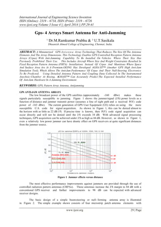
- 1. International Journal of Engineering Science Invention ISSN (Online): 2319 – 6734, ISSN (Print): 2319 – 6726 www.ijesi.org Volume 3 Issue 4 || April 2014 || PP.29-41 www.ijesi.org 29 | Page Gps- 4 Arrays Smart Antenna for Anti-Jamming 1, Dr.M.Ramkumar Prabhu & 2, U.T.Sasikala Dhaanish Ahmed College of Engineering, Chennai, India. ABSTRACT: A Miniaturized GPS A n t e n n a Array Technology That Reduces The Size Of The Antenna Elements And The Array Dimensions. This Technology Enables GPS Controlled Reception Pattern Antenna Arrays (Crpas) With Anti-Jamming Capability To Be Installed On Vehicles Where Their Size Has Previously Prohibited Their Use. This Includes Aircraft Where Size And Weight Constraints Resulted In Fixed Reception Pattern Antenna (FRPA) Installations Instead Of Crpas And Munitions Where Space And Surface Area Are At A Premium.OEING Has Developed AGHA ST™ (Another GPS High Anti-Jam Simulation Tool), Which Allows The Anti-Jam Performance Of Crpas And Their Null-Steering Electronics To Be Predicted. Using Detailed Antenna Pattern And Coupling Data Collected In The Instrumented Anechoic Chamber At Boeing, AGHAST™ Can Accurately Predict The Expected Installed Performance Of Anti-Jam Hardware In A Jamming Environment. KEYWORDS: GPS, Pattern Array Antenna, Antijamming GPS ANTI-JAM ANTENNA ARRAYS The low broadcast power of the GPS satellites (approximately -160 dBw) makes these signals particularly susceptible to jamming. Figure 1 shows the jammer/signal (J/S) power levels as a function of distance and jammer transmit power (assumes a line of sight path and a received P(Y) code power of -163 dBw). The current generation of GPS User Equipment (UE) relies on using the more susceptible C/A code for signal acquisition. As shown in Figure 1, this can be denied almost to the horizon with as little as 22 dB J/S. If precise time is known, then P(Y) code signal acquisition can occur directly and will not be denied until the J/S exceeds 34 dB. With advanced signal processing techniques, GPS acquisition can be achieved under J/S as high as 44 dB. However, as shown in Figure 1, even a relatively low power jammer can have drastic effect on GPS receivers at quite significant distances from the jammer source. Figure 1 Jammer effects versus distance The most effective performance improvements against jammers are provided through the use of controlled radiation pattern antennas (CRPAs). These antennas increase the J/S margin to 84 dB with a conventional GPS receiver and further improvements to 98 dB can be expected with advanced receiver designs. The basic design of a simple beam-steering or null- forming antenna array is illustrated in Figure 2. The simple example shown consists of four microstrip patch antenna elements with
- 2. Gps- 4 Arrays Smart Antenna for Anti-Jamming www.ijesi.org 30 | Page antenna weighting and phase shifter circuitry to adapt the array pattern. More advanced anti-jam (A/J) electronics are currently under development by the USAF using adaptive digital signal processing algorithms. The miniaturized antenna design is being developed to be compatible with the A/J electronics currently in use with conventional CRPA arrays or the newer GPS Antenna System (GAS)1. All of these A/J systems are designed to detect multiple jammer signals and place a null in the antenna pattern in the location of the jammer. Figure 2 Basic phased array antenna design GPS MINI-ARRAY CONCEPT A key factor in the array performance is the number of antenna elements. The more elements available, the more nulls can be placed in the direction of a jammer. The number of jammers which can be nulled by a GPS array is equal to one less than the number of antenna elements (N- 1). With digital electronics the multiple elements can also be used to add gain to the GPS satellite signal through beam steering.2 The more elements in a beam forming array, the greater the degree of directionality in the array and the greater the gain in the direction of the desired signals. With N elements, the beam- steering gain is increased by 10 log10N db.To prevent spatial correlation, the antenna array elements in a conventional array must be placed half a wavelength apart. This changes the relative phase shift between elements as a function of the input signal elevation angle so that there is no phase shift (0o) when the signal is perpendicular to the array and a half cycle phase shift between elements (180o) when the signal is horizontal to the array.The null-depth that can be achieved through the use of a phased array is a function of the phase angle separation between the received GPS signals at the antenna elements and the received jammer signal. In Figure 3 the geometry is illustrated for a simple two-element array. The ideal case is when the phase angle separation between the received jammer signals is 0.5 cycles. In this case, total cancellation can be achieved of the jammer signals by summing the signals from the two elements, without any attenuation of the received signal power from the satellites.In Figure 4 the possible null-depth vers us the phase angle separation for the jammer signal between the two elements is plotted for typical received signal conditions (C/N0=44 dB-Hz, J/S=30 dB). In a conventional array, reducing the spacing between the elements will result in reducing the null-depth that can be achieved. For example, if the antenna element spacing in a conventional CRPA was reduced by 35% then the maximum null-depth that could be achieved would be only 4 dB! Figure 3 Two element array geometry
- 3. Gps- 4 Arrays Smart Antenna for Anti-Jamming www.ijesi.org 31 | Page Figure 4 Null Depth as a function of phase angle delta The key to achieving good A/J performance while shrinking the antenna size is to maintain the same phase relationship between the received signals at the miniature antenna array as for a conventional (half wavelength) full- size array. As described in this paper, it is possible to shrink the size of the individual antenna elements by designing small patch elements using a high dielectric substrate. This allows more antenna elements to be clustered closer together in the same over-all array footprint. The major innovation presented in the mini-array antenna design developed by NAVSYS is the introduction of a shaped high-dielectric superstrate, which allows the same half- cycle phase relationship to be maintained between antenna elements as in a full-size array, while also reducing the mutual coupling between elements. The combination of these effects enable the over-all size of a GPS antenna array to be shrunk while still providing equivalent A/J protection to a full-size conventional GPS CRPA. GPS MINI-ARRAY APPLICATIONS Many of the smaller munitions in operation or in development do not have a form factor that allows for a conventional CRPA to be installed. Because of size and weight constraints, some host aircraft within the Air Force and Navy have also elected to install FRPA antennas which cannot provide the A/J protection needed in many tactical environments. The GPS mini-array will enable A/J capability to be pro vided on many small munitions, aircraft and other host vehicles where the size and weight of the conventional CRPA array has previously been prohibitive. For example, current programs, such as the Joint Direct Attack Munition (JDAM), Joint Air-to- Surface Standoff Missile (JASSM), and the Joint Standoff Weapon (JSOW), will be able to benefit from the reduced size but full performance of the mini-array technology. MINI-ARRAY DESIGN OVERVIEW The miniature array is composed of a ground plane, a substrate wit h the antenna elements on its surface, and a superstrate on top of the elements. The dielectric constant of the substrate is increased so that the size of the antenna elements can be reduced. This allows the antenna element spacing to be reduced. By controlling the design of the antenna elements, the efficiency is increased so that they have the same gain as a standard GPS antenna element. By adjusting the dielectric constant and shape of the superstrate, the mutual coupling between the antenna elements is minimized and the reduced antenna spacing is scaled so that it appears to be effectively /2 in its beamforming or null steering performance.A summary o f the mini-array specifications is shown below in Table 1. As can be seen, the array was designed for receiving the GPS L1 frequency with sufficient bandwidth to receive both C/A code and P code versions of GPS data. To provide optimum performance as a CRPA, its elements have been arranged into square with /2 antenna spacing. Figure 5 displays the top view of the current mini-array configuration. Figure 6 shows a photograph of the mini-array evaluated in this paper.
- 4. Gps- 4 Arrays Smart Antenna for Anti-Jamming www.ijesi.org 32 | Page Table 1 Summary of mini-array specification Center Frequency 1575.42 MHz (at L1) Bandwidth 20 MHz (1575.42 +/- 10 MHz) Input Impedance 60 Ohms VSWR 2.4:1 Maximum Polarization Right Hand Circular Polarization (RHCP) Array Size 6 Inches Diameter Array Configuration Square Number of Elements 4 Element Type Rectangular Feed Arrangement Probe Feed with Coaxial Figure 5 Top view of the 4-element mini-array configuration Figure 6 Photo of 4-element mini-array MEASUREMENT RESULTS Voltage Standing Wave Ratio (VSWR) The measured VSWR for each of the four elements is less than 2.4:1 within a frequency band of 1575.42 +/ - 10.0 MHz. This is worse than the previous antenna due to the trimming of the substrate so that it would fit on the Boeing test fixture. A typical measured VSWR versus frequency is shown in Figure 8. Reflection Coefficient The m e a s u r e d reflection coefficient of the mini-array antenna elements is close to 0 within the L1 frequency band. A typical measured reflection coefficient is shown in Figure 8. As shown here, the center frequency of the matching does not occur at the GPS L1 frequency. Even s o, the antennas still meet the 2.4:1 VSWR specification.
- 5. Gps- 4 Arrays Smart Antenna for Anti-Jamming www.ijesi.org 33 | Page Figure 7 the measured VSWR for antenna 1 of the array Figure 8 The measured reflection coefficient for antenna 1 of the mini-array Mutual Coupling The transmission coefficient between the elements is used to indicate the mutual coupling between them. The strongest mutual coupling occurs between Element 2 and Element 3, and the transmission coefficient is below –14 dB in the L1 frequency band (1575.42 +/- 10 MHz). Figure 9 and Figure 10 show two typical measured transmission coefficients between the four elements of the mini-array.
- 6. Gps- 4 Arrays Smart Antenna for Anti-Jamming www.ijesi.org 34 | Page Figure 9 The measured transmission coefficient between element 3 and element 2 Figure 10 The measured transmission coefficient between element 4 and element 3 Antenna Receiving Pattern vs Polarization The antenna receiving patterns of the mini-array antenna element were measured inside the Microwave Anechoic Chamber at the Boeing Military Aircraft And Missile Systems Group Facility in St. Louis, Missouri. The array was attached to the tail end of Boeing PGM tailkit mockup with “NORTH” (between elements 1 and 2) aligned with the “fixed fin” or +x axis. A photo of this setup is shown in Figure 11. To generate the antenna patterns, a set of antenna data was collected at the L1 frequency for horizontal polarization, vertical polarization, and circular polarization at 216 angular points which is approximately a 15° spacing.
- 7. Gps- 4 Arrays Smart Antenna for Anti-Jamming www.ijesi.org 35 | Page Figure 11 Mini-array mounted on Boeing PGM tailkit. Figure 12 Horizontal polarization for antenna element 1 at GPS L1 frequency, zenith Figure 13 Vertical polarization for antenna element 1 at GPS L1 frequency, zenith The “zenith” hemisphere is centered on the tail of the PGM, while the “nadir” hemisphere is centered on the nose. As shown in Figure 12 through Figure 14, the mini- array antenna element has a relative consistent pattern at different polarizations. Figure 14 Circular polarization for antenna element 1 at GPS L1 frequency, zenith Antenna Receiving Pattern vs angle As shown in Figure 14, a “lens” affect is definitely seen where each antenna has its antenna pattern peaked in the direction directly across the array (ie, element 1 is at +x +y while the gain peak is at –x–y). As shown in Figure 14 through Figure 17, this “lens” affect does show up in all antenna elements. In addition, Figure 18 shows that the affect also is visible in the nadir hemisphere as well as the zenith hemisphere.
- 8. Gps- 4 Arrays Smart Antenna for Anti-Jamming www.ijesi.org 36 | Page Figure 15 Circular polarization for antenna element 2 at GPS L1 frequency, zenith Antenna Array Gain Measured with the NAVSYS High Gain Advanced GPS Receiver (HAGR) The NAVSYS HAGR is a GPS digital beamforming electronic system which consists of a digital front end (DFE) unit, a digital beam-steering (DBS) card, a correlation accelerator chip (CAC) board, and the associated software [2]. The DFE unit converts the L1- band radio frequency (RF) signals to digital signals. The HAGR-DFE unit can be configured to include up to 16 DFE channels, each connecting to one antenna element. Figure 16 Circular polarization for antenna element 3 at GPS L1 frequency, zenith Figure 17 Circular polarization for antenna element 4 at GPS L1 frequency, zenith
- 9. Gps- 4 Arrays Smart Antenna for Anti-Jamming www.ijesi.org 37 | Page Figure 18 Circular polarization for antenna element 1 at GPS L1 frequency, nadir The digital data from the DFE outputs are processed by the DBS card to provide a composite signal output for each satellite being tracked. There are 8 DBS channels, and each can be used to provide the composite signal for a single satellite. The CAC board contains the correlator chips that perform the code correlations and the complex multiplications needed for code and carrier tracking of GPS satellite signals. There are 8 CAC channels each connecting to a single DBS channel. The test set-up was approximately 40 feet away from the NAVSYS building, and a 3’x3’ metal plate was used as the ground plane for the 4-element mini-array. The mini- array enables the HAGR to continuously track the satellites and update the navigation data. Figure 19 to Figure 24 display the measured C/N0 values from satellite PRNs 30, 24, 10, 5, 4, and 8 for the 4-element mini-array with a NAVSYS HAGR and a single AT575-97 reference antenna with a Novatel GPS receiver. On avera ge, the 4- element mini-array provides a gain of 4 to 6 dB in C/N0 as compared to the AT575-97 reference antenna. To verify that the mini-array would not affect GPS satellite acquisition performance in anti-jam systems, no amplitude compensation was implemented in the HAGR. Figure 19 The measured C/N0 values from PRN 30 for the 4-element mini-array with a NAVSYS HAGR and for an AT575-97 reference antenna with a Novatel receiver
- 10. Gps- 4 Arrays Smart Antenna for Anti-Jamming www.ijesi.org 38 | Page Figure 20 The measured C/N0 values from PRN 24 Figure 21 The measured C/N0 values from PRN 10 Figure 22 The measured C/N0 values from PRN 5
- 11. Gps- 4 Arrays Smart Antenna for Anti-Jamming www.ijesi.org 39 | Page Figure 23 The measured C/N0 values from PRN 4 Figure 24 The measured C/N0 values from PRN 8 These plots show proper satellite tracking for elevation angles from 15 degrees up to 72 degrees. As seen in these various plots, the “lens” affect found in the individual antenna patterns does not affect the GPS satellite acquisition performance of the mini-array. Anechoic Chamber Measurements of the GPS Carrier Signal’s Phase Difference between Mini-Array Antenna Elements Figure 25, Figure 26, and Figure 27 show the measured phase difference between elements 1-3, 4-3, and 2-3 versus the elevation angle in the y-z plane for E incident waves. As shown in these figures, the phase difference between elements 1-3 and 2-3 is very close to 0.5 cycle when the elevation angle is 0 degrees. Also, the phase difference between elements 4-3 is very close to 0 cycle as expected since the base-line vector is perpendicular to the line-of-sight vector. It is noted that the actual physical spacing between adjacent elements is only 0.2236 cycle in free-space. Figure 25 The measured phase difference between Element 1 and Element 3 (reference element) versus elevation angle in the y-z plane for Eqq incident waves
- 12. Gps- 4 Arrays Smart Antenna for Anti-Jamming www.ijesi.org 40 | Page Figure 26 The measured phase difference between Element 4 and Element 3 (reference element) versus elevation angle in the y-z plane for Eqq incident waves Figure 27 the measured p h a s e d i f f er en ce b e t w e e n Element 2 and Element 3 (reference element) versus elevation angle in the y-z plane for Eqq incident waves Analytical Anti-Jam Performance Boeing has developed AGHAST™, which allows accurate anti-jam performance of CRPAs and other anti- jam hardware to be predicted. Using the detailed antenna pattern data collected in their instrumented anechoic chamber at Boeing, AGHAST™ can accurately predict the expected field test performance of anti-jam hardware. Using these tools, Boeing performed a rough assessment on the mini-array performance. Even though this does not guarantee what the actual performance might be, it should provide an indication of this performance. As shown in Figure 28 and Figure 29, this performance was evaluated for both the zenith and nadir hemispheres. As shown, the null performance is quite uniform with very good performance. Figure 28 Relative nulling performance of the mini- array, zenith hemisphere
- 13. Gps- 4 Arrays Smart Antenna for Anti-Jamming www.ijesi.org 41 | Page Figure 29 Relative nulling performance of the mini- array, nadir hemisphere CONCLUSION The purpose of this research effort was to design and fabricate a miniaturized antenna array for GPS applications that can be used to provide GPS anti- jamming enhancements. The following technical objectives have been achieved. Test each array pattern for a variety of progressive amplitude and phase arrangements The 6” form factor mini-array was tested in an anechoic chamber to measure its antenna patterns. In addition, it was also measured in an anechoic chamber and with live satellite observations to evaluate the measured phase relationship between elements with the phase relationship predicted using the mini-array simulation tools. The simulation tools predicted that the miniature antenna array phase relationship should be within 0.1 cycles of a full size antenna array. The anechoic chamber observations showed excellent agreement with these results. Measure the performance of the miniaturized array by demonstrating satellite tracking with an L1 GPS receiver Digital beam steering High Gain Advanced GPS Receiver (HAGR) was used to demonstrate the antenna array performance. By applying the predicted ½ wavelength phase shifts to each antenna element digitally, the HAGR forms a phase coherent signal sum from each of the 4 antenna elements which is predicted to have a theoretical 6 dB gain improvement over a single element GPS receiver. In Figure 19 to Figure 24, the C/N0 from the GPS satellites tracked are shown compared with a conventional GPS receiver. These show that the mini- array is providing 4 to 6 dB gain per satellite as expected. Analyze boundary effects between the superstrate and free space The Boeing design tool was developed to analyze the potential anti-jam performance of various anti-jam components. This design tool was used to analyze the predicted A/J performance of the miniaturized antenna array and showed very good results. In conclusion, this research effort has successfully demonstrated a technique for miniaturizing a GPS phase array antenna. We achieved our objective of developing and testing a 4-element antenna array in a 8” form factor and demonstrating that its performance is equivalent to a full-size array with ½wavelength separation. REFERENCES [1] Critical Item Development Specification for the Controlled Reception Pattern Antenna (CRPA) Line Replaceable Unit (LRU) of the NAVSTAR Global Positioning System Antenna System-1 (GAS-1), CI- GAS1/CRPA-300A, Appendix II to SS-GAS1-300A, 24 Apr 1998. [2] A. Brown, R. Silva, G. Zhang, “Test Results of a High [3] Gain Advanced GPS Receiver,” ION 55 th Annual [4] Meeting, Cambridge, MA, June 1999; and A. Brown, J. Wang, “High Accuracy Differential and Kinematic GPS Performance Using a Digital Beam-Steering Array,” ION GPS ’99 Meeting, Nashville, TN, Sept. 1999.