Weitere ähnliche Inhalte
Ähnlich wie 40120140504013
Ähnlich wie 40120140504013 (20)
Mehr von IAEME Publication
Mehr von IAEME Publication (20)
Kürzlich hochgeladen (20)
40120140504013
- 1. International Journal of Electronics and Communication Engineering & Technology (IJECET), ISSN 0976 –
6464(Print), ISSN 0976 – 6472(Online), Volume 5, Issue 4, April (2014), pp. 95-102 © IAEME
95
REMOTELY CONTROLLING THE PARAMETERS USING LABVIEW
THROUGH ZC702 (XC7Z020CLG484 SOC) CAN INTERFACE
Saurabh Nair1
, Rachana Rajpal2
, Abhijeet Kumar3
, Sachin Gajjar4
1, 4
Department of Electronics & Communication Engineering, Nirma University, Gujarat, India,
2, 3
Department of Electronics & Instrumentation, Institute for Plasma Research, Gujarat, India,
ABSTRACT
This application will be used to control various parameters such as Gain, Filter Frequency
etc. in Electronics and Data Acquisition System. We will be using CAN Interface for remotely
controlling and LabVIEW software for user interface. The CAN protocol provides high reliability,
which is one of the important features in DAQ systems. The prototype application has been designed
for the ZC702 evaluation board which consists of the XC7Z020CLG484 SoC chip, which has two
ARM Cortex A9 processor cores, FPGA and an inbuilt CAN controller. Since most of the controller
such as CAN, Ethernet, USB and I2C are available on the chip, it reduces the external ICs required
for the system, thereby making the system compact. The Xilinx SDK is used to write a code in C for
the Cortex A9 processor. The FPGA is programmed in VHDL to produce the control signals and
data for the electronics and data acquisition board. The XC7Z020 SoC, optimizes the communication
between Processing System and the Programmable Logic. The prototype application has been
implemented and tested in the lab. The paper will describe about the hardware and the software for
the prototype application.
Key Words: CAN Protocol, Cortex A9, Generic Interrupt Controller, LabVIEW, ZC702.
1. INTRODUCTION
Controlling various parameters such as Gain, Filter Frequency, etc. in Electronics and Data
Acquisition System is important in Plasma Research. Currently, the task is fulfilled by using an 8-bit
controller P80C592, which has an integrated CAN controller. CAN protocol based communication
was used to communicate between the controller and the user interface. A separate FPGA IC is used
to provide the large number of I/Os needed for the design. The FPGA is simply used to increase the
available I/Os, while the control signals and buffers are implemented using separate decoder ICs,
INTERNATIONAL JOURNAL OF ELECTRONICS AND
COMMUNICATION ENGINEERING & TECHNOLOGY (IJECET)
ISSN 0976 – 6464(Print)
ISSN 0976 – 6472(Online)
Volume 5, Issue 4, April (2014), pp. 95-102
© IAEME: www.iaeme.com/ijecet.asp
Journal Impact Factor (2014): 7.2836 (Calculated by GISI)
www.jifactor.com
IJECET
© I A E M E
- 2. International Journal of Electronics and Communication Engineering & Technology (IJECET), ISSN 0976 –
6464(Print), ISSN 0976 – 6472(Online), Volume 5, Issue 4, April (2014), pp. 95-102 © IAEME
96
switches and Buffer ICs. As the demands from data acquisition increase faster processing and
smaller size of the system becomes necessary.
Thus, the basic need which was to be addressed was faster processing of data and integrating
the hardware into the FPGA and thereby, controlling the parameters of the electronics and data
acquisition system. Xilinx has developed aSoC IC of the ZYNQ 7000 family called the
XC7Z020CLG484, which has two ARM Cortex A9 cores, CAN controller and integrated FPGA.
The Cortex A9 processor is a 32 bit processor and provides faster processing compared to the 8-bit
controller. Integrating the hardware into the FPGA reduces the required physical hardware, both on
the controller module and the Electronics and Data Acquisition System. It also provides a large
number of I/Os. Thus, all problems regarding the earlier system can be overcome, by using the
XC7Z020CLG484 SoC from Xilinx.
The Xilinx provides an evaluation board based on XC7Z020CLG484 SoC called ZC702.
This board provides all the interfaces supported by the SoC. The prototype application discussed in
this paper has been tested on the ZC702 evaluation board.
2. METHOD
2.1 Prototype Application
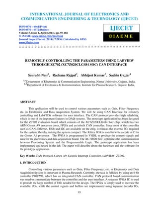
The block diagram and data flow for the prototype application is a shown in Fig 1.
Fig.1: Prototype application hardware block diagram
LabVIEW is a software created by National Instruments. It uses the graphical programming
language called G, which does not require any text as in C, C++, etc. The LabVIEW program
running on the PC provides the User Interface. It allows the user to input parameter values, which is
transmitted to the SoC as a CAN packet. As the PC does not have a CAN interface, it sends the data
to the USB interface, where a NI-USB to CAN interface is provided.
LabVIEW
running on
PC (user
terminal)
NI-USB to
CAN
Electronics &
Data
Acquisition
Board
XC7Z020SoC
Level
Translator
- 3. International Journal of Electronics and Communication Engineering & Technology (IJECET), ISSN 0976 –
6464(Print), ISSN 0976 – 6472(Online), Volume 5, Issue 4, April (2014), pp. 95-102 © IAEME
97
The NI USB 847x CAN interface is used in the current application. It has a built in
transceiver and hardware time stamping. It uses a 9 pin male DB9 connector to interface to the CAN
bus.
At the CAN interface, a level translator is provided on the ZC702. The ZC702 uses the
TXS0104E level translator, which is a bi-directional level translator. The level translator has an
Output Enable pin, which is active low. In ZC702, this bit connected to MIO 9 pin, which is by
default high. For the successful communication on CAN network, this pin must be set low by
software.
Using the Xilinx 14.6 PlanAhead software, the hardware can be selected. The
XC7Z020CLG484 SoC is to be selected as the primary hardware in PlanAhead. The PlanAhead
serves as the top layer which controls and links to the various other softwares by Xilinx such as, ISE,
XPS and SDK. The PlanAhead links the project to the XPS, in which we can create a custom
hardware. The VHDL code for the hardware can be written in PlanAhead and added to the current
project. The PlanAhead generates the hardware bit file. Then, it links the project to Xilinx SDK,
where the user C code is to be written and First Stage Boot Loader is added to the project. At the
SoC, the CAN communication program written in SDK is being run in the interrupt mode. The SoC
also has the bit file generated in PlanAhead loaded into the FPGA. Thus the hardware is built into the
FPGA. The CAN packet is received by the Processing System in the SoC through the level
translator. The CAN controller inbuilt in the SoC decodes the received raw CAN packet, determines
the address field, timestamp, length of data and the data bytes. The C program running in the SoC,
processes the received data and then sends them to the FPGA. The SoC provides an interface
between the Processing System and the FPGA (Programmable Logic) through an Extended
Multiplexed I/O (EMIO), which can have a maximum width of 64 bits. The FPGA receives the
processed data from the Processing System through the EMIO. Based on the received data, the
hardware in the FPGA generates the required control signals and the parameter values (data) for the
Electronics and Data Acquisition System. The FPGA also constantly monitors certain system signals
and sends them to the Processing System. Whenever there is any change in the signals being
monitored, the Processing System notifies it to the user by displaying the change in the LabVIEW
user terminal by sending a CAN packet.
2.2 Testing of prototype Application on ZC702
Before designing the hardware, the prototype has been tested on the evaluation board. In
PlanAhead ZC702 is to be selected as the target board. XPS has the hardware template for the
evaluation board. The signals monitored by the FPGA are those of module ID and the Electronics
and Data Acquisition System modules which are inserted.Since the hardware is not available, the
insertion and removal of modules is imitated using the switches available on the board.The hardware
logic implemented in FPGA generates the control signals and parameter values, which are to be
given to the external hardware is brought out on FMC connector terminal. The module ID which is
of 8 bits is also read from the pins on the FMC connector.
The following figure Fig. 2 shows the actual hardware blocks used and the flow of data
between them for the purpose of testing the prototype application on the ZC702 Evaluation Board.
- 4. International Journal of Electronics and Communication Engineering & Technology (IJECET), ISSN 0976 –
6464(Print), ISSN 0976 – 6472(Online), Volume 5, Issue 4, April (2014), pp. 95-102 © IAEME
98
Fig. 2: Actual hardware block diagram and data flow for testing on ZC702
Hardware developed in PlanAhead is a bit file, loaded into the FPGA. The CAN controller is
running in the interrupt mode. The Processing System constantly reads the Module ID and the
switches SW12_A, SW12_B, SW5 and SW7. These switches imitate the behaviour of a module
being inserted or removed. The user interface program in LabVIEW is constantly running. Whenever
any of the values (Module ID or switches) change, the Processing System sends a CAN packet to the
LabVIEW with the modified data. For the purpose of testing, as no modules were actually inserted,
the Module ID has the default value of 0xFF. The user will thus know which modules are inserted.
When the user wants to change the parameter value, he will write a CAN packet, with the required
parameters, Module to be enabled, Type of parameter to be changed and the Channel to be used. The
Processing System receives this CAN packet, processes it and sends the information to the hardware
in FPGA. Based on the information the FPGA receives from the hardware and the state of the
switches (SW12_A, SW12_B, SW5 and SW7), the hardware generates the appropriate control
signals (module enable and type and channel enable) and the parameter value. Thus, we verified the
functionality of the hardware and software for the prototype application.
Processing System
LabVIEW
User
Interface
Programmable Logic (FPGA)
NI-USB to
CAN
Interface
and Level
translator
SW 12_B
SW 12_A
SW 5
SW 7
EMIO
Module ID
CAN Controller
Hardware
developed in
PlanAhead
Module Enables
Type and Channel Enables
Parameter value (Gain/Filter)
Tx CAN
pkt
Tx CAN
pkt
Rx CAN
pkt
Rx CAN
pkt
Decode
bits and
parameter
values
LPC FMC
Connector
- 5. International Journal of Electronics and Communication Engineering & Technology (IJECET), ISSN 0976 –
6464(Print), ISSN 0976 – 6472(Online), Volume 5, Issue 4, April (2014), pp. 95-102 © IAEME
99
3. RESULTS
3.1 LabVIEW Front Panel Output
Fig. 3: LabVIEW Front Panel Output
This LabVIEW application is used for remotely controlling the parameters of the Electronics
and Data Acquisition System. In Fig. 3, the "CAN Interface parameters" allows the user to set the
parameters for the CAN communication. In this block, the user can select which interface is to be
used, parameters like baud rate, read and write queue length, comparator and mask values and
whether to transmit with time stamping. The "Write Control and Inputs" facilitates the user to input
the values for controlling the parameters and to write the CAN packet. The Write Control input
selects whether to enable the write operation in the hardware implemented in the FPGA. 'Type'
determines the type of parameter to be controlled (Gain or Filter), 'Module' to select the module to be
enabled, 'Channel No.' to select which channel in a module is to be used, 'Gain' to set the gain
parameter, 'Filter' to set the filter parameter and 'WRITE' to write the inputs to the CAN bus and
transmits them. The "Output path and CAN packets read" allows the user to provide a path for the
location for data to be stored, to display the CAN packets received and to stop the communication.
The 2D output array 'CAN packet received', displays the data received in the CAN packets by the
LabVIEW. The Data column in the 2D output array shows the 8 bytes of data received and displayed
in the hexadecimal format. The data bytes are displayed from left to right as bytes 0 to 7. The first
byte represents the modules which are inserted into the system, second byte displays the module ID
of the module enabled which by default has a value of “FF”, third byte represents the data used by
the FPGA (PL) to generate the control signals for the Electronics and Data Acquisition System and
the fourth byte is the actual parameter values to change the gain or filter parameters. Bytes 5 to 7 are
not used, and hence are “00”. STOP button stops the communication.
- 6. International Journal of Electronics and Communication Engineering & Technology (IJECET), ISSN 0976 –
6464(Print), ISSN 0976 – 6472(Online), Volume 5, Issue 4, April (2014), pp. 95-102 © IAEME
100
3.2 Simulation result for the gain control
Fig. 4: Simulation result for the gain control displaying the data and control lines
In Fig 4 above, the decode[6:0] contains the write control bits, type, module and channel
information. decode[6] contains the write control bit sent by the user and should be one, for the
control signals and parameter values to be generated. decode[5:4] contains the input about the type of
parameter to be controlled, decode[3] contains the channel number input to select which channel in
the module is to be enabled and decode[2:0] determines which module is to be enabled.
mod_ins[3:0] is an input port where each bit determines which module is presently inserted into the
system. Because we have used 4 switches from the evaluation board for the testing purpose, it is a 4
bit input port.data_in[7:0] is the data or parameter value which is to be written to the module and
provided by the user. data_in[7:4] contains the value for the filter parameter and data[3:0] contains
the value for the gain parameter. data_out[3:0] is the port connected to the electronics and data
acquisition system module data lines. Initially, based on decode[2:0], the required module enable
signals are generated i.e. mod_ena_sig. It is then logicallyanded with the mod_ins[3:0], to determine
if the module desired to be enabled is actually present or not. The result of anding is stored in the
mod_ins_test signal and compared with the generated enable signal, and if they match the module
enable signal is sent to output. If the module enable signal is generated, only then based on the other
decode bits decode[5:3], is the channel and type enable signal generated. Based on the type of data to
be written, specified by decode[5:4], either data_in[7:4] or data_in[3:0] is written to data_out.
3.3 GAIN Control output
Fig. 5: Signal with gain 1
- 7. International Journal of Electronics and Communication Engineering & Technology (IJECET), ISSN 0976 –
6464(Print), ISSN 0976 – 6472(Online), Volume 5, Issue 4, April (2014), pp. 95-102 © IAEME
101
Fig. 6: Signal with gain 2
Fig. 7: Signal with gain 4
Fig. 8: Signal with gain 8
Fig 5, 6, 7 and 8 shows the output obtained from the gain test. Fig 6 shows the output when
the gain has been set to a value of 1. Thus, it is also the same as input. Fig 7 shows the output when
the gain is set to 2. Similarly, Fig 8 shows the output for a gain of 4 and Fig 9 shows the output for a
gain of 8. The input is a 200mV square wave.
4. CONCLUSION
Thus, the XC7Z020 provides both the Processing System and Programmable Logic, which
provides the advantage of writing software as per need for the Processing System and reducing
physical hardware by including the hardware in the Programmable Logic. The hardware provides
much faster operation and the integration of Programmable Logic with Processing System optimizes
any delay possible between the processor and FPGA. In the current case, the Processing System is
used basically as an interface between LabVIEW and the Programmable Logic. The Processing
System uses the CAN interface to receive and send data to the LabVIEW. The PL uses the data
received from PS and generates the required control signals (enables) and data to appropriate
modules. The data was sent to the gain modules and it provided the desired results. Thus, it could be
concluded that remote controlling of gain parameter could be done successfully.
- 8. International Journal of Electronics and Communication Engineering & Technology (IJECET), ISSN 0976 –
6464(Print), ISSN 0976 – 6472(Online), Volume 5, Issue 4, April (2014), pp. 95-102 © IAEME
102
5. REFERENCES
[1]. NI USB CAN Interfaces, http://sine.ni.com/nips/cds/view/p/lang/en/nid/203382.
[2]. TXS0104E 4 bit bi directional voltage level translator.
[3]. UG585 ZYNQ 7000 All Programmable SoC Technical Reference Manual, Xilinx.
[4]. UG873 ZYNQ 7000 All Programmable SoC: Concepts, Tools and Techniques, Xilinx.
[5]. ZYNQ 7000 All Programmable SoC Hardware Development, Xilinx.
[6]. ZYNQ 7000 All Programmable SoC Design Workshop Bare Metal Software Development.
[7]. LabVIEW, Getting Started with LabVIEW, NATIONAL INSTRUMENTS.
[8]. Dr.V.Balaji, “Study of Model Predictive Control using NI LabVIEW”, International Journal of
Advanced Research in Engineering & Technology (IJARET), Volume 3, Issue 2, 2012,
pp. 257 - 266, ISSN Print: 0976-6480, ISSN Online: 0976-6499.