SlideShare ist ein Scribd-Unternehmen logo
1 von 52
8/30/2016 bhargava 1
SEM
Saurabh Bhargava
Objectives of this lecture
• At the end of the lecture one should be able to
answer the questions related to-
– Basic principles of SEM
– Instrumentation of SEM
– Image generation/ formation by SEM
– Collection & interpretation of images of SEM
– Forensic applications of SEM
8/30/2016 bhargava 2
8/30/2016 bhargava 3
M
A
G
N
I
F
I
C
A
T
I
O
N
C
O
M
PL
E
XI
T
Y
&
C
O
S
T
NEED..?
Resolution
• Resolution is defined as the
ability to distinguish two very
small and closely-spaced objects
as separate entities.
• Resolution is best when the
distance separating the two tiny
objects is small.
• Resolution is determined by
certain physical parameters that
include the wavelength of light,
and the light-gathering power of
the objective and condenser
lenses.
8/30/2016 bhargava 4
Conti..
• A simple mathematical equation defines the
smallest distance (dmin) separating the two
very small objects:
dmin = 1.22 x wavelength
N.A. objective + N.A. condenser
8/30/2016 bhargava 5
Electron Microscopy
• An electron microscope is a microscope that uses accelerated electrons as a
source of illumination.
• Electron microscopes were developed due to the limitations of Light
Microscopes which are limited by the physics of light.
• In the early 1930's there was a scientific desire to see the fine details of the
interior structures of organic cells (nucleus, mitochondria...etc.).
• This required >10000x magnifications which could not be achieved by simple
light/optical microscopy.
• Because the wavelength of an electron can be up to 100,000 times shorter
than that of visible light photons, the electron microscope has a
higher resolving power than a light microscope and can reveal the structure of
smaller objects.
8/30/2016 bhargava 6
Historical Aspects of Electron
Microscopy
– The development of a SEM began a few yrs after the
invention of a TEM by Ruska in 1931, but the
commercialization of the SEM required about 30 yrs.
– In 1935, the original prototype of the SEM, which scans the
specimen with an e- beam to obtain an image, was made
by Knoll(Germany).
– In 1942, Zworykin (USA), developed a SEM for observing a
bulk specimens.
– In 1965, Cambridge Scientific Instrument (UK) & JOEL
(Japan) first commercialized SEM individually.
8/30/2016 bhargava 7
8/30/2016 bhargava 8
Fig: SEM image of pneumonia pathogen Fig: SEM image of a ‘diatom’
8/30/2016 bhargava 9
Fig: SEM image of pollen grains Fig: SEM image of house fly compound eye
surface @450x
Fig: SEM image of kidney stone
(Calcium Oxalate Dihydrate crystals)
8/30/2016 bhargava 10
Fig: SEM image of the tip of a needle @50x & @750x magnifications
Information Retrieved
• Topography :
– The surface features of an object (hardness, reflectivity...etc.)
• Morphology:
– The shape and size of the particles (ductility, strength, shape ...etc.)
• Composition:
– The elements and compounds that the object is composed of and
the relative amounts of them.
• Crystallographic Information:
– How the atoms are arranged in the object.
8/30/2016 bhargava 11
SEM
• Scanning electron microscopy (SEM) uses a
focused electron probe to extract structural
and chemical information point-by-point from
a region of interest in the sample.
• The high spatial resolution of a SEM makes it a
powerful tool to characterise a wide range of
specimens at the nanometre to micrometre
length scales.
8/30/2016 bhargava 12
Scanning Electron Microscope (SEM)
• A SEM is a type of electron microscope that
images a sample by scanning it with a high-
energy beam of electrons in a raster scan pattern.
• The electrons interact with the atoms that make
up the sample producing signals that contain
information about the sample's surface
topography, composition, and other properties
such as electrical conductivity.
8/30/2016 bhargava 13
What Happens When e- Beam Strikes The
Specimen..?
• When the specimen is bombarded with the electron beam, electrons
are ejected from the atoms of the specimen surface.
• Inelastic scattering, place the atom in the excited state. The excited
atom “wants ” to return to a ground or unexcited state. Hence the
atoms will relax giving off the excess energy.
• X-rays, Cathod luminescence are some of the ways of relaxation for
an excited atom.
• A resulting electron vacancy is filled by an electron from a higher
shell, and an X-ray is emitted to balance the energy difference
between the two electrons.
8/30/2016 bhargava 14
8/30/2016 bhargava 15
Electron Beam & Sample Interactions
8/30/2016 bhargava 16
Secondary Electrons Generation
Secondary Electron
Generation
-sample electrons ejected by the
primary beam [green line]
-low energy
-surface detail & topography
8/30/2016 bhargava 17
Back Scatter Electron Generation
Backscattered Electron Generation
-SEM-BSE
-primary beam electrons
-high energy
-composition and topography
[specimen atomic number]
8/30/2016 bhargava 18
X-Rays Generation
•X-Rays are
produced to
balance the
difference of
energy when
an electron
from outer
shell replaces
the one from
inner shell.
Instrumentation
1. Electron optical system (to
produce electrons)
– Electron gun, condenser lens,
objective lens, deflection coil.
2. Specimen stage (to place the
specimen).
3. Secondary e- detector (to
collect secondary e-).
4. Image display unit.
5. Operating system
– The electron optical system
and a space surrounding the
specimen are kept at vacuum.
8/30/2016 bhargava 19
Electron Gun
• It produces an electron beam.
• The electrons are emitted from a
filament (cathode) made of a thin
tungsten wire, (about 0.1mm ) by
heating the filament at high
temperature (about 2800k).
• These e- flow as an e- beam,
towards the metal/anode (positive
voltage).
• If the hole is made at the centre of
the plate the e- beam flows through
this hole.
8/30/2016 bhargava 20
Magnetic Lens System
• Condenser lens is a lens placed right below the electron gun and is used
to adjust the width of the electron beam as per requirement.
• The condenser lens controls the intensity of the electron beam reaching
the specimen.
• The objective lens brings the electron beam into focus on the specimen.
• The scanning coils deflect the electron beam horizontally and vertically
over the specimen surface. This is also called rastering.
– A fine e- beam is required for SEM, for better performance.
8/30/2016 bhargava 21
Specimen Stage/Chamber
• It receives and supports the
specimen.
• Specimen stage should be able to
perform the horizontal and vertical
movements smoothly.
• The horizontal movement is used
for selection of the field while the
vertical movement is used to
change the image resolution.
8/30/2016 bhargava 22Fig: SEM sample chamber (opened)
Secondary e- Detector
• It is used for detecting the secondary e-
emitted from the specimen.
• The secondary e- are attracted to the
high voltage (10 kV) and then generate
light when they hit the scintillator
(fluorescent substance).
• This light is directed to a photon-
multiplier tube (PMT) through a light
guide.
• The light is converted to the electrons,
and these are amplified as an electric
signal.
8/30/2016 bhargava 23
Image Display Unit
• The output signals from the secondary electron detector are
amplified through PMT and then transferred to the display
unit forming a SEM image.
8/30/2016 bhargava 24
8/30/2016 bhargava 25
Vacuum System
• The electron optical system and the specimen chamber must be
kept at a high vacuum of 10-3 to 10-4 Pa.
• High vacuum that minimises scattering of the electron beam before
reaching the specimen.
• This is important as scattering of the electron beam will increase
the probe size and reduce the resolution.
• Thus , these components are evacuated by diffusion pump.
8/30/2016 bhargava 26
Working of SEM
• The electron gun produces an electron beam when tungsten wire is
heated by current.
• This beam is accelerated by the anode.
• The beam travels through electromagnetic fields and lenses, which focus
the beam down toward the sample.
• A mechanism of deflection coils guide the beam so that it scans the
surface of the sample in a rectangular frame (raster pattern).
• When the beam touches the surface of the sample, it produces:
– Secondary electrons (SE)
– Back scattered electrons (BSE)
– X - Rays...
• The emitted SE is collected by SED and converted into signal that is sent
to a screen which produces final image.
• Additional detectors collect these X-rays, BSE and produce
corresponding images.
8/30/2016 bhargava 27
Secondary Electron (SE) Images
– For routine scanning electron microscope images, secondary
electrons (SE) form the usual image of the surface.
– Secondary electrons are low energy electrons formed by inelastic
scattering and have energy of less than 50eV.
– The low energy of these electrons allows them to be collected easily.
– This is achieved by placing a positively biased grill on the front of the
SE detector.
– The positive grill attracts the negative electrons and they go through it
into the detector. This is the case for the Everhart-Thornley
detector which is most commonly used.
– To increase the yield of SE emitted from the specimen, heavy metals
such as gold or platinum are routinely used to coat specimens (sputter).
An extremely thin layer is applied (~10 nm).
– This coating is applied for two main reasons:
1. Non-conductive specimens are often coated to reduce surface charging that
can block the path of SE and cause distortion of signal level and image form;
and
2. Low atomic number (Z) specimens (e.g. biological samples) are coated
8/30/2016 bhargava 28
8/30/2016 bhargava 29
Detectors
• Secondary electron detector
(SED) –
– Everhart-Thornley Detector
– Due to the low energies of
secondary electrons (SE) (~2 to
50 eV) they are ejected only
from near-surface layers.
– Therefore, secondary electron
imaging (SEI) is ideal for
recording topographical
information.
– To attract (collect) these low-
energy electrons, usually
around +200 to 300V is applied
to the cage at the front end of
the detector.
– A higher kV (7 to 12kV) is
applied inside the cage i.e. to
the scintillator, to accelerate
the electrons into the
scintillator screen.
8/30/2016 bhargava 30
8/30/2016 bhargava 31
SE image formation
Backscattered electron (BSE) images
• Backscattered (BS) electrons are high-energy electrons (>50 eV) ejected back out from the
sample. These BSE are used to produce a different kind of image.
• Such an image uses contrast to tell us about the average atomic number of the sample.
• The higher the average atomic number, the more primary electrons are scattered
(bounced) back out of the sample. This leads to a brighter image for such materials.
• For example, a grain of sand (in a mixture of mineral sand) that is made up of a titanium
mineral looks whiter than a grain made of a silicon material (Ti versus Si). In the image
(next slide), the left picture is taken using backscattered electrons. Here there is a
difference in contrast between the grains labelled Si and Ti whereas in the right image,
taken using secondary electrons, there is no difference in contrast between these grains.
8/30/2016 bhargava 32
8/30/2016 bhargava 33
Backscattered electron detector
(BSED)
• The BSED is mounted below the objective lens pole piece and centred
around the optic axis.
• As the specimen surface is scanned by the incident electron beam,
backscattered electrons (BSE) are generated, the yield of which is controlled
by the topographical, physical and chemical characteristics of the sample.
• Both compositional or topographical backscattered electron images (BEI)
can be recorded depending on the window of electron energies selected for
image formation.
8/30/2016 bhargava 34
8/30/2016 bhargava 35
Light’ region is made up predominantly
of Fe. (i.e. the heaviest element)
‘Grey’ region is made up
predominantly of Ca.
‘Dark’ region is made up predominantly
of Si and Al. (i.e. the lightest elements)
Types
1. Conventional (high vacuum) scanning electron microscopy (SEM)
– This is the most common type of machine.
– It requires a dry, conductive sample (often achieved by applying a thin
layer of metal to the surface with a technique called sputtering).
– The sample must be able to withstand a high vacuum.
2. Variable Pressure or Low Vacuum scanning electron microscopy
(LVSEM)
– This type of machine is basically like a conventional SEM but has the
advantage in low vacuum (LV) mode that the pressure can be adjusted in
the sample chamber.
– This means LVSEM can be used to image the surface of non-conductive
samples (no metal needs to be added to the surface of such samples).
– It is particularly useful for viewing polymers, biological samples, and
museum samples that cannot be changed in any way, particulate samples,
and geological materials.
8/30/2016 bhargava 36
8/30/2016 bhargava 37
3. Cryo-scanning electron microscope (Cryo-SEM)
– Cryo stands for frozen. A cryo-scanning electron microscope is a
conventional SEM that has been fitted with specific equipment that allows
samples to be viewed in the frozen state.
– This is particularly useful for directly viewing hydrated (wet) samples,
delicate biological samples, hydrogels, food, bio-films, foams, fats, and
waxes, suspensions, pharmaceuticals and nano-particles.
4. Environmental scanning electron microscope (ESEM)
– This machine is designed to view a sample in its natural state, without the
need for desiccation.
– Sample temperature and specimen chamber vapour pressure can both be
controlled, allowing samples to be heated, cooled, wetted or dried.
– Imaging of biological processes, for example pollen tube growth in real time
through wetting of pollen.
Applications
• SEM is one of the most versatile technique, and can be used to-
I. Image morphology of samples
II. Image compositional and some bonding differences
III. Examine wet and dry samples while viewing them (only in an ESEM)
IV. View frozen material (in a SEM with a cryostage)
V. Generate X-rays from samples for microanalysis (EDS)
VI. View/map grain orientation/crystallographic orientation and study
related information like heterogeneity
8/30/2016 bhargava 38
X- Ray Analysis
8/30/2016 bhargava 39
•An incoming high-energy electron
dislodges an inner-shell electron in the
target, leaving a vacancy in the shell
•An outer shell electron then “jumps” to fill
the vacancy
•A characteristic x-ray (equivalent to the
energy change in the “jump”) is generated
or
•The energy released from an electron
replacement event produces a photon with
an energy exactly equal to the drop in
energy.
1. Elemental identification
2. Chemical characterization
3. Quantitative analysis
8/30/2016 bhargava 40
•When an electron from a K-shell is replaced by one from the next closest shell (L), it is
designated as a Kα event
•When an electron from a K-shell is replaced by one from the second closest shell (M),
it is designated as a Kβ event
8/30/2016 bhargava 41
Lα - When an electron from a L-shell is replaced by one from the next closest shell
(M).
The K shell will never donate its electron as this would require an increase in
energy, not a drop.
8/30/2016 bhargava 42
•Certain events such as Mα, Lβ, and Kγ are only possible in atoms of sufficient atomic weight.
•Each element has a family of characteristic X-rays associated with it
8/30/2016 bhargava 43
8/30/2016 bhargava 44
Instrumentation
Gunshot Residue (GSR) Analysis
• GSR is often found on criminals and also on victims if shot at close
range.
• Particles are very characteristic, therefore presence of these particles
forms evidence of firing a gun.
• Particles normally consist of Pb (lead), Sb (antimony) and Ba (barium).
• The proportion of elements present in GSR differ slightly and databases
of GSR from different manufacturers can be used to identify what
ammunition was used in a crime.
• New ammunition: environmentally friendly (no Sb).
8/30/2016 bhargava 45
Gunshot Residue (GSR) Analysis
8/30/2016 bhargava 46
8/30/2016 bhargava 47
GSR Analysis on cloth fibre
•Bullet fragments
(blue) can be
identified on cloth
fibres and
distinguished from
other metal pieces
by their elemental
composition
Analysis
• Qualitative Analysis:
– Peak energy gives qualitative information about the constituent elements
• Quantitative Analysis:
– Peak intensity gives information about the element composition to find the
changes in concentration of elements.
8/30/2016 bhargava 48
FORENSIC APPLICATIONS
• In forensic science, police laboratories use the SEM to
examine and compare evidence, such as
1. Metal fragments,
2. Paint,
3. Inks,
4. Hair,
5. Fibers
– To prove a person's guilt or innocence. Through careful
examination, detectives are able to determine if samples
collected from a crime scene have properties that match
the scenario developed by detectives.
8/30/2016 bhargava 49
Entomological applications
• In the field of biological
science, large objects such as
insects and animal tissues and
small objects such as bacteria
and viruses are studied by
SEM.
• There are many applications
for the SEM in this field and
one of them is entomological
taxonomy.
8/30/2016 bhargava 50
Soils & Rocks
• Investigation of soils and geological
samples is common place
in scanning electron microscopy.
• Analysis of morphology can inform
about weathering processes.
• Compositional differences can be
seen with the help of
backscattered electron imaging
(image).
• Microanalysis can provide details
on elemental composition.
8/30/2016 bhargava 51
Sample preparation
• The correct preparation is vital to getting good quality
information from your sample. A poorly mounted or
incorrectly processed sample can lead to viewing
artefacts.
• For non-conductive samples that need coating to make
them conductive, consider whether compositional
information is required (e.g. BSE imaging, X-ray
spectroscopy), and use a carbon coating if this is the case.
• Gold or platinum metal coatings will interfere with the
compositional signal from the sample.
8/30/2016 bhargava 52

Weitere ähnliche Inhalte

Was ist angesagt?

scanning electron microscope (SEM)
scanning electron microscope (SEM)scanning electron microscope (SEM)
scanning electron microscope (SEM)Himanshu Dixit
 
ATOMIC FORCE MICROSCOPE MITHILESH CHOUDHARY
ATOMIC FORCE MICROSCOPE MITHILESH CHOUDHARYATOMIC FORCE MICROSCOPE MITHILESH CHOUDHARY
ATOMIC FORCE MICROSCOPE MITHILESH CHOUDHARYAnjan Anant
 
Energy Dispersive Spectroscopy
Energy Dispersive SpectroscopyEnergy Dispersive Spectroscopy
Energy Dispersive SpectroscopySaad Shaukat
 
X-ray Photoelecctron Spectroscopy (XPS)
X-ray Photoelecctron Spectroscopy (XPS)X-ray Photoelecctron Spectroscopy (XPS)
X-ray Photoelecctron Spectroscopy (XPS)faheem maqsood
 
Atomic force microscope
Atomic force microscopeAtomic force microscope
Atomic force microscopeSenthil Arasan
 
( EDAX)energy Dispersive xray spectroscopy
( EDAX)energy Dispersive xray spectroscopy ( EDAX)energy Dispersive xray spectroscopy
( EDAX)energy Dispersive xray spectroscopy RushikeshGParit
 
Transmission electron microscope, high resolution tem and selected area elect...
Transmission electron microscope, high resolution tem and selected area elect...Transmission electron microscope, high resolution tem and selected area elect...
Transmission electron microscope, high resolution tem and selected area elect...Nano Encryption
 
SCANNING PROBE MICROSCOPY .
SCANNING PROBE MICROSCOPY .SCANNING PROBE MICROSCOPY .
SCANNING PROBE MICROSCOPY .sana shaikh
 
Transmission electron microscope
Transmission electron microscopeTransmission electron microscope
Transmission electron microscopeSenthil Arasan
 
Presentation on SEM (Scanning Electron Microscope)
Presentation on SEM (Scanning Electron Microscope) Presentation on SEM (Scanning Electron Microscope)
Presentation on SEM (Scanning Electron Microscope) Farshina Nazrul
 
Xps (x ray photoelectron spectroscopy)
Xps (x ray photoelectron spectroscopy)Xps (x ray photoelectron spectroscopy)
Xps (x ray photoelectron spectroscopy)Zaahir Salam
 
AFM (Atomic Force Microscopy)
AFM (Atomic Force Microscopy)AFM (Atomic Force Microscopy)
AFM (Atomic Force Microscopy)Chemist Sohaib
 
Secondary Ion Mass Spectroscopy (SIMS) PPT
 Secondary Ion Mass Spectroscopy (SIMS)  PPT Secondary Ion Mass Spectroscopy (SIMS)  PPT
Secondary Ion Mass Spectroscopy (SIMS) PPTDhivyaprasath Kasinathan
 
Transmission electron microscope
Transmission electron microscopeTransmission electron microscope
Transmission electron microscopeRaj Mohan
 

Was ist angesagt? (20)

scanning electron microscope (SEM)
scanning electron microscope (SEM)scanning electron microscope (SEM)
scanning electron microscope (SEM)
 
STM ppt
STM pptSTM ppt
STM ppt
 
ATOMIC FORCE MICROSCOPE MITHILESH CHOUDHARY
ATOMIC FORCE MICROSCOPE MITHILESH CHOUDHARYATOMIC FORCE MICROSCOPE MITHILESH CHOUDHARY
ATOMIC FORCE MICROSCOPE MITHILESH CHOUDHARY
 
SEM- scanning electron microscope
SEM- scanning electron microscope SEM- scanning electron microscope
SEM- scanning electron microscope
 
Energy Dispersive Spectroscopy
Energy Dispersive SpectroscopyEnergy Dispersive Spectroscopy
Energy Dispersive Spectroscopy
 
Tem
TemTem
Tem
 
X-ray Photoelecctron Spectroscopy (XPS)
X-ray Photoelecctron Spectroscopy (XPS)X-ray Photoelecctron Spectroscopy (XPS)
X-ray Photoelecctron Spectroscopy (XPS)
 
Atomic force microscope
Atomic force microscopeAtomic force microscope
Atomic force microscope
 
( EDAX)energy Dispersive xray spectroscopy
( EDAX)energy Dispersive xray spectroscopy ( EDAX)energy Dispersive xray spectroscopy
( EDAX)energy Dispersive xray spectroscopy
 
Transmission electron microscope, high resolution tem and selected area elect...
Transmission electron microscope, high resolution tem and selected area elect...Transmission electron microscope, high resolution tem and selected area elect...
Transmission electron microscope, high resolution tem and selected area elect...
 
SEM & FESEM.pptx
SEM & FESEM.pptxSEM & FESEM.pptx
SEM & FESEM.pptx
 
SCANNING PROBE MICROSCOPY .
SCANNING PROBE MICROSCOPY .SCANNING PROBE MICROSCOPY .
SCANNING PROBE MICROSCOPY .
 
Transmission electron microscope
Transmission electron microscopeTransmission electron microscope
Transmission electron microscope
 
SEM,TEM & AFM
SEM,TEM & AFMSEM,TEM & AFM
SEM,TEM & AFM
 
Presentation on SEM (Scanning Electron Microscope)
Presentation on SEM (Scanning Electron Microscope) Presentation on SEM (Scanning Electron Microscope)
Presentation on SEM (Scanning Electron Microscope)
 
Xps (x ray photoelectron spectroscopy)
Xps (x ray photoelectron spectroscopy)Xps (x ray photoelectron spectroscopy)
Xps (x ray photoelectron spectroscopy)
 
AFM (Atomic Force Microscopy)
AFM (Atomic Force Microscopy)AFM (Atomic Force Microscopy)
AFM (Atomic Force Microscopy)
 
Secondary Ion Mass Spectroscopy (SIMS) PPT
 Secondary Ion Mass Spectroscopy (SIMS)  PPT Secondary Ion Mass Spectroscopy (SIMS)  PPT
Secondary Ion Mass Spectroscopy (SIMS) PPT
 
Transmission electron microscope
Transmission electron microscopeTransmission electron microscope
Transmission electron microscope
 
Scanning electron microscopy (sem)
Scanning electron microscopy (sem)Scanning electron microscopy (sem)
Scanning electron microscopy (sem)
 

Ähnlich wie Scanning Electron Microscopy (SEM) lecture

2018 HM-scanning electron microscope
2018 HM-scanning electron microscope2018 HM-scanning electron microscope
2018 HM-scanning electron microscopeHarsh Mohan
 
SEM discription.pptx
SEM discription.pptxSEM discription.pptx
SEM discription.pptxMariaAshraf25
 
revised ppt (sem) Shoaib group ).pptx
revised ppt (sem) Shoaib group ).pptxrevised ppt (sem) Shoaib group ).pptx
revised ppt (sem) Shoaib group ).pptxMariaAshraf25
 
Scanning electron microscope(SEM)
Scanning electron microscope(SEM)Scanning electron microscope(SEM)
Scanning electron microscope(SEM)AdarshaS13
 
Lecture_3_conventional-Microscope.pdf
Lecture_3_conventional-Microscope.pdfLecture_3_conventional-Microscope.pdf
Lecture_3_conventional-Microscope.pdfyaleybro
 
Electron microscope
Electron microscopeElectron microscope
Electron microscopeReena Rai
 
ELECTRON MICROSCOPY (TEM & SEM)
ELECTRON MICROSCOPY (TEM & SEM)ELECTRON MICROSCOPY (TEM & SEM)
ELECTRON MICROSCOPY (TEM & SEM)ADITYA ARYA
 
Scanning Electron Microscopy - SEM
Scanning Electron Microscopy - SEM Scanning Electron Microscopy - SEM
Scanning Electron Microscopy - SEM Stephen Raj D
 
Scanning electron microscopy
Scanning electron microscopyScanning electron microscopy
Scanning electron microscopyGanesh Shinde
 
scanning electron microscope for analysis
scanning electron microscope for analysisscanning electron microscope for analysis
scanning electron microscope for analysisM Ali Mohsin
 
Scanning electron microscope
Scanning electron microscopeScanning electron microscope
Scanning electron microscopeSuganyaPaulraj
 
Chapter-3. Electron Microscopy.pptx
Chapter-3. Electron Microscopy.pptxChapter-3. Electron Microscopy.pptx
Chapter-3. Electron Microscopy.pptxShivayogiPatil2
 
Scanning Electron Microscope
Scanning Electron Microscope Scanning Electron Microscope
Scanning Electron Microscope VrushankSalimath
 

Ähnlich wie Scanning Electron Microscopy (SEM) lecture (20)

2018 HM-scanning electron microscope
2018 HM-scanning electron microscope2018 HM-scanning electron microscope
2018 HM-scanning electron microscope
 
SEM discription.pptx
SEM discription.pptxSEM discription.pptx
SEM discription.pptx
 
revised ppt (sem) Shoaib group ).pptx
revised ppt (sem) Shoaib group ).pptxrevised ppt (sem) Shoaib group ).pptx
revised ppt (sem) Shoaib group ).pptx
 
electron microscopy
electron microscopyelectron microscopy
electron microscopy
 
Scanning and Transmission Electron Microscope
Scanning and Transmission Electron MicroscopeScanning and Transmission Electron Microscope
Scanning and Transmission Electron Microscope
 
Scanning electron microscope(SEM)
Scanning electron microscope(SEM)Scanning electron microscope(SEM)
Scanning electron microscope(SEM)
 
Lecture_3_conventional-Microscope.pdf
Lecture_3_conventional-Microscope.pdfLecture_3_conventional-Microscope.pdf
Lecture_3_conventional-Microscope.pdf
 
Electron microscope
Electron microscopeElectron microscope
Electron microscope
 
ELECTRON MICROSCOPY (TEM & SEM)
ELECTRON MICROSCOPY (TEM & SEM)ELECTRON MICROSCOPY (TEM & SEM)
ELECTRON MICROSCOPY (TEM & SEM)
 
Scanning Electron Microscopy - SEM
Scanning Electron Microscopy - SEM Scanning Electron Microscopy - SEM
Scanning Electron Microscopy - SEM
 
Scanning electron microscopy
Scanning electron microscopyScanning electron microscopy
Scanning electron microscopy
 
Dr nh mat.char notes
Dr nh   mat.char  notesDr nh   mat.char  notes
Dr nh mat.char notes
 
scanning electron microscope for analysis
scanning electron microscope for analysisscanning electron microscope for analysis
scanning electron microscope for analysis
 
Scanning electron microscope
Scanning electron microscopeScanning electron microscope
Scanning electron microscope
 
Electron microscopy
Electron microscopyElectron microscopy
Electron microscopy
 
Chapter-3. Electron Microscopy.pptx
Chapter-3. Electron Microscopy.pptxChapter-3. Electron Microscopy.pptx
Chapter-3. Electron Microscopy.pptx
 
Sem n tem
Sem n temSem n tem
Sem n tem
 
Scanning Electron Microscope
Scanning Electron Microscope Scanning Electron Microscope
Scanning Electron Microscope
 
Electron microscopy
Electron microscopyElectron microscopy
Electron microscopy
 
SEM TEM NOTES.pptx
SEM TEM NOTES.pptxSEM TEM NOTES.pptx
SEM TEM NOTES.pptx
 

Mehr von Saurabh Bhargava

Mehr von Saurabh Bhargava (13)

Crime scene investigation lecture
Crime scene investigation  lectureCrime scene investigation  lecture
Crime scene investigation lecture
 
Introduction to Forensic science labs in India
Introduction to Forensic science labs in IndiaIntroduction to Forensic science labs in India
Introduction to Forensic science labs in India
 
Hyphenated techniques
Hyphenated techniquesHyphenated techniques
Hyphenated techniques
 
Light microscopy
Light microscopyLight microscopy
Light microscopy
 
forensic facial reconstruction
forensic facial reconstructionforensic facial reconstruction
forensic facial reconstruction
 
Strychnine nux vomica
Strychnine nux vomicaStrychnine nux vomica
Strychnine nux vomica
 
aberrations
aberrations aberrations
aberrations
 
Plant poisons
Plant poisonsPlant poisons
Plant poisons
 
Forensic Odontology
Forensic OdontologyForensic Odontology
Forensic Odontology
 
Identification
IdentificationIdentification
Identification
 
Paternity index
Paternity indexPaternity index
Paternity index
 
Glass analysis
Glass analysisGlass analysis
Glass analysis
 
Narco & beos
Narco & beosNarco & beos
Narco & beos
 

Kürzlich hochgeladen

“Oh GOSH! Reflecting on Hackteria's Collaborative Practices in a Global Do-It...
“Oh GOSH! Reflecting on Hackteria's Collaborative Practices in a Global Do-It...“Oh GOSH! Reflecting on Hackteria's Collaborative Practices in a Global Do-It...
“Oh GOSH! Reflecting on Hackteria's Collaborative Practices in a Global Do-It...Marc Dusseiller Dusjagr
 
SOCIAL AND HISTORICAL CONTEXT - LFTVD.pptx
SOCIAL AND HISTORICAL CONTEXT - LFTVD.pptxSOCIAL AND HISTORICAL CONTEXT - LFTVD.pptx
SOCIAL AND HISTORICAL CONTEXT - LFTVD.pptxiammrhaywood
 
Z Score,T Score, Percential Rank and Box Plot Graph
Z Score,T Score, Percential Rank and Box Plot GraphZ Score,T Score, Percential Rank and Box Plot Graph
Z Score,T Score, Percential Rank and Box Plot GraphThiyagu K
 
Software Engineering Methodologies (overview)
Software Engineering Methodologies (overview)Software Engineering Methodologies (overview)
Software Engineering Methodologies (overview)eniolaolutunde
 
Beyond the EU: DORA and NIS 2 Directive's Global Impact
Beyond the EU: DORA and NIS 2 Directive's Global ImpactBeyond the EU: DORA and NIS 2 Directive's Global Impact
Beyond the EU: DORA and NIS 2 Directive's Global ImpactPECB
 
Measures of Central Tendency: Mean, Median and Mode
Measures of Central Tendency: Mean, Median and ModeMeasures of Central Tendency: Mean, Median and Mode
Measures of Central Tendency: Mean, Median and ModeThiyagu K
 
BASLIQ CURRENT LOOKBOOK LOOKBOOK(1) (1).pdf
BASLIQ CURRENT LOOKBOOK  LOOKBOOK(1) (1).pdfBASLIQ CURRENT LOOKBOOK  LOOKBOOK(1) (1).pdf
BASLIQ CURRENT LOOKBOOK LOOKBOOK(1) (1).pdfSoniaTolstoy
 
Interactive Powerpoint_How to Master effective communication
Interactive Powerpoint_How to Master effective communicationInteractive Powerpoint_How to Master effective communication
Interactive Powerpoint_How to Master effective communicationnomboosow
 
Activity 01 - Artificial Culture (1).pdf
Activity 01 - Artificial Culture (1).pdfActivity 01 - Artificial Culture (1).pdf
Activity 01 - Artificial Culture (1).pdfciinovamais
 
Arihant handbook biology for class 11 .pdf
Arihant handbook biology for class 11 .pdfArihant handbook biology for class 11 .pdf
Arihant handbook biology for class 11 .pdfchloefrazer622
 
mini mental status format.docx
mini    mental       status     format.docxmini    mental       status     format.docx
mini mental status format.docxPoojaSen20
 
Q4-W6-Restating Informational Text Grade 3
Q4-W6-Restating Informational Text Grade 3Q4-W6-Restating Informational Text Grade 3
Q4-W6-Restating Informational Text Grade 3JemimahLaneBuaron
 
Introduction to AI in Higher Education_draft.pptx
Introduction to AI in Higher Education_draft.pptxIntroduction to AI in Higher Education_draft.pptx
Introduction to AI in Higher Education_draft.pptxpboyjonauth
 
Industrial Policy - 1948, 1956, 1973, 1977, 1980, 1991
Industrial Policy - 1948, 1956, 1973, 1977, 1980, 1991Industrial Policy - 1948, 1956, 1973, 1977, 1980, 1991
Industrial Policy - 1948, 1956, 1973, 1977, 1980, 1991RKavithamani
 
A Critique of the Proposed National Education Policy Reform
A Critique of the Proposed National Education Policy ReformA Critique of the Proposed National Education Policy Reform
A Critique of the Proposed National Education Policy ReformChameera Dedduwage
 
Grant Readiness 101 TechSoup and Remy Consulting
Grant Readiness 101 TechSoup and Remy ConsultingGrant Readiness 101 TechSoup and Remy Consulting
Grant Readiness 101 TechSoup and Remy ConsultingTechSoup
 
1029 - Danh muc Sach Giao Khoa 10 . pdf
1029 -  Danh muc Sach Giao Khoa 10 . pdf1029 -  Danh muc Sach Giao Khoa 10 . pdf
1029 - Danh muc Sach Giao Khoa 10 . pdfQucHHunhnh
 
Presentation by Andreas Schleicher Tackling the School Absenteeism Crisis 30 ...
Presentation by Andreas Schleicher Tackling the School Absenteeism Crisis 30 ...Presentation by Andreas Schleicher Tackling the School Absenteeism Crisis 30 ...
Presentation by Andreas Schleicher Tackling the School Absenteeism Crisis 30 ...EduSkills OECD
 

Kürzlich hochgeladen (20)

“Oh GOSH! Reflecting on Hackteria's Collaborative Practices in a Global Do-It...
“Oh GOSH! Reflecting on Hackteria's Collaborative Practices in a Global Do-It...“Oh GOSH! Reflecting on Hackteria's Collaborative Practices in a Global Do-It...
“Oh GOSH! Reflecting on Hackteria's Collaborative Practices in a Global Do-It...
 
SOCIAL AND HISTORICAL CONTEXT - LFTVD.pptx
SOCIAL AND HISTORICAL CONTEXT - LFTVD.pptxSOCIAL AND HISTORICAL CONTEXT - LFTVD.pptx
SOCIAL AND HISTORICAL CONTEXT - LFTVD.pptx
 
Z Score,T Score, Percential Rank and Box Plot Graph
Z Score,T Score, Percential Rank and Box Plot GraphZ Score,T Score, Percential Rank and Box Plot Graph
Z Score,T Score, Percential Rank and Box Plot Graph
 
Software Engineering Methodologies (overview)
Software Engineering Methodologies (overview)Software Engineering Methodologies (overview)
Software Engineering Methodologies (overview)
 
Beyond the EU: DORA and NIS 2 Directive's Global Impact
Beyond the EU: DORA and NIS 2 Directive's Global ImpactBeyond the EU: DORA and NIS 2 Directive's Global Impact
Beyond the EU: DORA and NIS 2 Directive's Global Impact
 
Measures of Central Tendency: Mean, Median and Mode
Measures of Central Tendency: Mean, Median and ModeMeasures of Central Tendency: Mean, Median and Mode
Measures of Central Tendency: Mean, Median and Mode
 
BASLIQ CURRENT LOOKBOOK LOOKBOOK(1) (1).pdf
BASLIQ CURRENT LOOKBOOK  LOOKBOOK(1) (1).pdfBASLIQ CURRENT LOOKBOOK  LOOKBOOK(1) (1).pdf
BASLIQ CURRENT LOOKBOOK LOOKBOOK(1) (1).pdf
 
Interactive Powerpoint_How to Master effective communication
Interactive Powerpoint_How to Master effective communicationInteractive Powerpoint_How to Master effective communication
Interactive Powerpoint_How to Master effective communication
 
Mattingly "AI & Prompt Design: The Basics of Prompt Design"
Mattingly "AI & Prompt Design: The Basics of Prompt Design"Mattingly "AI & Prompt Design: The Basics of Prompt Design"
Mattingly "AI & Prompt Design: The Basics of Prompt Design"
 
Activity 01 - Artificial Culture (1).pdf
Activity 01 - Artificial Culture (1).pdfActivity 01 - Artificial Culture (1).pdf
Activity 01 - Artificial Culture (1).pdf
 
Arihant handbook biology for class 11 .pdf
Arihant handbook biology for class 11 .pdfArihant handbook biology for class 11 .pdf
Arihant handbook biology for class 11 .pdf
 
mini mental status format.docx
mini    mental       status     format.docxmini    mental       status     format.docx
mini mental status format.docx
 
Q4-W6-Restating Informational Text Grade 3
Q4-W6-Restating Informational Text Grade 3Q4-W6-Restating Informational Text Grade 3
Q4-W6-Restating Informational Text Grade 3
 
Introduction to AI in Higher Education_draft.pptx
Introduction to AI in Higher Education_draft.pptxIntroduction to AI in Higher Education_draft.pptx
Introduction to AI in Higher Education_draft.pptx
 
Industrial Policy - 1948, 1956, 1973, 1977, 1980, 1991
Industrial Policy - 1948, 1956, 1973, 1977, 1980, 1991Industrial Policy - 1948, 1956, 1973, 1977, 1980, 1991
Industrial Policy - 1948, 1956, 1973, 1977, 1980, 1991
 
Código Creativo y Arte de Software | Unidad 1
Código Creativo y Arte de Software | Unidad 1Código Creativo y Arte de Software | Unidad 1
Código Creativo y Arte de Software | Unidad 1
 
A Critique of the Proposed National Education Policy Reform
A Critique of the Proposed National Education Policy ReformA Critique of the Proposed National Education Policy Reform
A Critique of the Proposed National Education Policy Reform
 
Grant Readiness 101 TechSoup and Remy Consulting
Grant Readiness 101 TechSoup and Remy ConsultingGrant Readiness 101 TechSoup and Remy Consulting
Grant Readiness 101 TechSoup and Remy Consulting
 
1029 - Danh muc Sach Giao Khoa 10 . pdf
1029 -  Danh muc Sach Giao Khoa 10 . pdf1029 -  Danh muc Sach Giao Khoa 10 . pdf
1029 - Danh muc Sach Giao Khoa 10 . pdf
 
Presentation by Andreas Schleicher Tackling the School Absenteeism Crisis 30 ...
Presentation by Andreas Schleicher Tackling the School Absenteeism Crisis 30 ...Presentation by Andreas Schleicher Tackling the School Absenteeism Crisis 30 ...
Presentation by Andreas Schleicher Tackling the School Absenteeism Crisis 30 ...
 

Scanning Electron Microscopy (SEM) lecture

  • 2. Objectives of this lecture • At the end of the lecture one should be able to answer the questions related to- – Basic principles of SEM – Instrumentation of SEM – Image generation/ formation by SEM – Collection & interpretation of images of SEM – Forensic applications of SEM 8/30/2016 bhargava 2
  • 4. Resolution • Resolution is defined as the ability to distinguish two very small and closely-spaced objects as separate entities. • Resolution is best when the distance separating the two tiny objects is small. • Resolution is determined by certain physical parameters that include the wavelength of light, and the light-gathering power of the objective and condenser lenses. 8/30/2016 bhargava 4
  • 5. Conti.. • A simple mathematical equation defines the smallest distance (dmin) separating the two very small objects: dmin = 1.22 x wavelength N.A. objective + N.A. condenser 8/30/2016 bhargava 5
  • 6. Electron Microscopy • An electron microscope is a microscope that uses accelerated electrons as a source of illumination. • Electron microscopes were developed due to the limitations of Light Microscopes which are limited by the physics of light. • In the early 1930's there was a scientific desire to see the fine details of the interior structures of organic cells (nucleus, mitochondria...etc.). • This required >10000x magnifications which could not be achieved by simple light/optical microscopy. • Because the wavelength of an electron can be up to 100,000 times shorter than that of visible light photons, the electron microscope has a higher resolving power than a light microscope and can reveal the structure of smaller objects. 8/30/2016 bhargava 6
  • 7. Historical Aspects of Electron Microscopy – The development of a SEM began a few yrs after the invention of a TEM by Ruska in 1931, but the commercialization of the SEM required about 30 yrs. – In 1935, the original prototype of the SEM, which scans the specimen with an e- beam to obtain an image, was made by Knoll(Germany). – In 1942, Zworykin (USA), developed a SEM for observing a bulk specimens. – In 1965, Cambridge Scientific Instrument (UK) & JOEL (Japan) first commercialized SEM individually. 8/30/2016 bhargava 7
  • 8. 8/30/2016 bhargava 8 Fig: SEM image of pneumonia pathogen Fig: SEM image of a ‘diatom’
  • 9. 8/30/2016 bhargava 9 Fig: SEM image of pollen grains Fig: SEM image of house fly compound eye surface @450x Fig: SEM image of kidney stone (Calcium Oxalate Dihydrate crystals)
  • 10. 8/30/2016 bhargava 10 Fig: SEM image of the tip of a needle @50x & @750x magnifications
  • 11. Information Retrieved • Topography : – The surface features of an object (hardness, reflectivity...etc.) • Morphology: – The shape and size of the particles (ductility, strength, shape ...etc.) • Composition: – The elements and compounds that the object is composed of and the relative amounts of them. • Crystallographic Information: – How the atoms are arranged in the object. 8/30/2016 bhargava 11
  • 12. SEM • Scanning electron microscopy (SEM) uses a focused electron probe to extract structural and chemical information point-by-point from a region of interest in the sample. • The high spatial resolution of a SEM makes it a powerful tool to characterise a wide range of specimens at the nanometre to micrometre length scales. 8/30/2016 bhargava 12
  • 13. Scanning Electron Microscope (SEM) • A SEM is a type of electron microscope that images a sample by scanning it with a high- energy beam of electrons in a raster scan pattern. • The electrons interact with the atoms that make up the sample producing signals that contain information about the sample's surface topography, composition, and other properties such as electrical conductivity. 8/30/2016 bhargava 13
  • 14. What Happens When e- Beam Strikes The Specimen..? • When the specimen is bombarded with the electron beam, electrons are ejected from the atoms of the specimen surface. • Inelastic scattering, place the atom in the excited state. The excited atom “wants ” to return to a ground or unexcited state. Hence the atoms will relax giving off the excess energy. • X-rays, Cathod luminescence are some of the ways of relaxation for an excited atom. • A resulting electron vacancy is filled by an electron from a higher shell, and an X-ray is emitted to balance the energy difference between the two electrons. 8/30/2016 bhargava 14
  • 15. 8/30/2016 bhargava 15 Electron Beam & Sample Interactions
  • 16. 8/30/2016 bhargava 16 Secondary Electrons Generation Secondary Electron Generation -sample electrons ejected by the primary beam [green line] -low energy -surface detail & topography
  • 17. 8/30/2016 bhargava 17 Back Scatter Electron Generation Backscattered Electron Generation -SEM-BSE -primary beam electrons -high energy -composition and topography [specimen atomic number]
  • 18. 8/30/2016 bhargava 18 X-Rays Generation •X-Rays are produced to balance the difference of energy when an electron from outer shell replaces the one from inner shell.
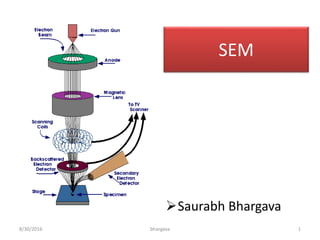
  • 19. Instrumentation 1. Electron optical system (to produce electrons) – Electron gun, condenser lens, objective lens, deflection coil. 2. Specimen stage (to place the specimen). 3. Secondary e- detector (to collect secondary e-). 4. Image display unit. 5. Operating system – The electron optical system and a space surrounding the specimen are kept at vacuum. 8/30/2016 bhargava 19
  • 20. Electron Gun • It produces an electron beam. • The electrons are emitted from a filament (cathode) made of a thin tungsten wire, (about 0.1mm ) by heating the filament at high temperature (about 2800k). • These e- flow as an e- beam, towards the metal/anode (positive voltage). • If the hole is made at the centre of the plate the e- beam flows through this hole. 8/30/2016 bhargava 20
  • 21. Magnetic Lens System • Condenser lens is a lens placed right below the electron gun and is used to adjust the width of the electron beam as per requirement. • The condenser lens controls the intensity of the electron beam reaching the specimen. • The objective lens brings the electron beam into focus on the specimen. • The scanning coils deflect the electron beam horizontally and vertically over the specimen surface. This is also called rastering. – A fine e- beam is required for SEM, for better performance. 8/30/2016 bhargava 21
  • 22. Specimen Stage/Chamber • It receives and supports the specimen. • Specimen stage should be able to perform the horizontal and vertical movements smoothly. • The horizontal movement is used for selection of the field while the vertical movement is used to change the image resolution. 8/30/2016 bhargava 22Fig: SEM sample chamber (opened)
  • 23. Secondary e- Detector • It is used for detecting the secondary e- emitted from the specimen. • The secondary e- are attracted to the high voltage (10 kV) and then generate light when they hit the scintillator (fluorescent substance). • This light is directed to a photon- multiplier tube (PMT) through a light guide. • The light is converted to the electrons, and these are amplified as an electric signal. 8/30/2016 bhargava 23
  • 24. Image Display Unit • The output signals from the secondary electron detector are amplified through PMT and then transferred to the display unit forming a SEM image. 8/30/2016 bhargava 24
  • 26. Vacuum System • The electron optical system and the specimen chamber must be kept at a high vacuum of 10-3 to 10-4 Pa. • High vacuum that minimises scattering of the electron beam before reaching the specimen. • This is important as scattering of the electron beam will increase the probe size and reduce the resolution. • Thus , these components are evacuated by diffusion pump. 8/30/2016 bhargava 26
  • 27. Working of SEM • The electron gun produces an electron beam when tungsten wire is heated by current. • This beam is accelerated by the anode. • The beam travels through electromagnetic fields and lenses, which focus the beam down toward the sample. • A mechanism of deflection coils guide the beam so that it scans the surface of the sample in a rectangular frame (raster pattern). • When the beam touches the surface of the sample, it produces: – Secondary electrons (SE) – Back scattered electrons (BSE) – X - Rays... • The emitted SE is collected by SED and converted into signal that is sent to a screen which produces final image. • Additional detectors collect these X-rays, BSE and produce corresponding images. 8/30/2016 bhargava 27
  • 28. Secondary Electron (SE) Images – For routine scanning electron microscope images, secondary electrons (SE) form the usual image of the surface. – Secondary electrons are low energy electrons formed by inelastic scattering and have energy of less than 50eV. – The low energy of these electrons allows them to be collected easily. – This is achieved by placing a positively biased grill on the front of the SE detector. – The positive grill attracts the negative electrons and they go through it into the detector. This is the case for the Everhart-Thornley detector which is most commonly used. – To increase the yield of SE emitted from the specimen, heavy metals such as gold or platinum are routinely used to coat specimens (sputter). An extremely thin layer is applied (~10 nm). – This coating is applied for two main reasons: 1. Non-conductive specimens are often coated to reduce surface charging that can block the path of SE and cause distortion of signal level and image form; and 2. Low atomic number (Z) specimens (e.g. biological samples) are coated 8/30/2016 bhargava 28
  • 30. Detectors • Secondary electron detector (SED) – – Everhart-Thornley Detector – Due to the low energies of secondary electrons (SE) (~2 to 50 eV) they are ejected only from near-surface layers. – Therefore, secondary electron imaging (SEI) is ideal for recording topographical information. – To attract (collect) these low- energy electrons, usually around +200 to 300V is applied to the cage at the front end of the detector. – A higher kV (7 to 12kV) is applied inside the cage i.e. to the scintillator, to accelerate the electrons into the scintillator screen. 8/30/2016 bhargava 30
  • 31. 8/30/2016 bhargava 31 SE image formation
  • 32. Backscattered electron (BSE) images • Backscattered (BS) electrons are high-energy electrons (>50 eV) ejected back out from the sample. These BSE are used to produce a different kind of image. • Such an image uses contrast to tell us about the average atomic number of the sample. • The higher the average atomic number, the more primary electrons are scattered (bounced) back out of the sample. This leads to a brighter image for such materials. • For example, a grain of sand (in a mixture of mineral sand) that is made up of a titanium mineral looks whiter than a grain made of a silicon material (Ti versus Si). In the image (next slide), the left picture is taken using backscattered electrons. Here there is a difference in contrast between the grains labelled Si and Ti whereas in the right image, taken using secondary electrons, there is no difference in contrast between these grains. 8/30/2016 bhargava 32
  • 34. Backscattered electron detector (BSED) • The BSED is mounted below the objective lens pole piece and centred around the optic axis. • As the specimen surface is scanned by the incident electron beam, backscattered electrons (BSE) are generated, the yield of which is controlled by the topographical, physical and chemical characteristics of the sample. • Both compositional or topographical backscattered electron images (BEI) can be recorded depending on the window of electron energies selected for image formation. 8/30/2016 bhargava 34
  • 35. 8/30/2016 bhargava 35 Light’ region is made up predominantly of Fe. (i.e. the heaviest element) ‘Grey’ region is made up predominantly of Ca. ‘Dark’ region is made up predominantly of Si and Al. (i.e. the lightest elements)
  • 36. Types 1. Conventional (high vacuum) scanning electron microscopy (SEM) – This is the most common type of machine. – It requires a dry, conductive sample (often achieved by applying a thin layer of metal to the surface with a technique called sputtering). – The sample must be able to withstand a high vacuum. 2. Variable Pressure or Low Vacuum scanning electron microscopy (LVSEM) – This type of machine is basically like a conventional SEM but has the advantage in low vacuum (LV) mode that the pressure can be adjusted in the sample chamber. – This means LVSEM can be used to image the surface of non-conductive samples (no metal needs to be added to the surface of such samples). – It is particularly useful for viewing polymers, biological samples, and museum samples that cannot be changed in any way, particulate samples, and geological materials. 8/30/2016 bhargava 36
  • 37. 8/30/2016 bhargava 37 3. Cryo-scanning electron microscope (Cryo-SEM) – Cryo stands for frozen. A cryo-scanning electron microscope is a conventional SEM that has been fitted with specific equipment that allows samples to be viewed in the frozen state. – This is particularly useful for directly viewing hydrated (wet) samples, delicate biological samples, hydrogels, food, bio-films, foams, fats, and waxes, suspensions, pharmaceuticals and nano-particles. 4. Environmental scanning electron microscope (ESEM) – This machine is designed to view a sample in its natural state, without the need for desiccation. – Sample temperature and specimen chamber vapour pressure can both be controlled, allowing samples to be heated, cooled, wetted or dried. – Imaging of biological processes, for example pollen tube growth in real time through wetting of pollen.
  • 38. Applications • SEM is one of the most versatile technique, and can be used to- I. Image morphology of samples II. Image compositional and some bonding differences III. Examine wet and dry samples while viewing them (only in an ESEM) IV. View frozen material (in a SEM with a cryostage) V. Generate X-rays from samples for microanalysis (EDS) VI. View/map grain orientation/crystallographic orientation and study related information like heterogeneity 8/30/2016 bhargava 38
  • 39. X- Ray Analysis 8/30/2016 bhargava 39 •An incoming high-energy electron dislodges an inner-shell electron in the target, leaving a vacancy in the shell •An outer shell electron then “jumps” to fill the vacancy •A characteristic x-ray (equivalent to the energy change in the “jump”) is generated or •The energy released from an electron replacement event produces a photon with an energy exactly equal to the drop in energy. 1. Elemental identification 2. Chemical characterization 3. Quantitative analysis
  • 40. 8/30/2016 bhargava 40 •When an electron from a K-shell is replaced by one from the next closest shell (L), it is designated as a Kα event •When an electron from a K-shell is replaced by one from the second closest shell (M), it is designated as a Kβ event
  • 41. 8/30/2016 bhargava 41 Lα - When an electron from a L-shell is replaced by one from the next closest shell (M). The K shell will never donate its electron as this would require an increase in energy, not a drop.
  • 42. 8/30/2016 bhargava 42 •Certain events such as Mα, Lβ, and Kγ are only possible in atoms of sufficient atomic weight. •Each element has a family of characteristic X-rays associated with it
  • 45. Gunshot Residue (GSR) Analysis • GSR is often found on criminals and also on victims if shot at close range. • Particles are very characteristic, therefore presence of these particles forms evidence of firing a gun. • Particles normally consist of Pb (lead), Sb (antimony) and Ba (barium). • The proportion of elements present in GSR differ slightly and databases of GSR from different manufacturers can be used to identify what ammunition was used in a crime. • New ammunition: environmentally friendly (no Sb). 8/30/2016 bhargava 45
  • 46. Gunshot Residue (GSR) Analysis 8/30/2016 bhargava 46
  • 47. 8/30/2016 bhargava 47 GSR Analysis on cloth fibre •Bullet fragments (blue) can be identified on cloth fibres and distinguished from other metal pieces by their elemental composition
  • 48. Analysis • Qualitative Analysis: – Peak energy gives qualitative information about the constituent elements • Quantitative Analysis: – Peak intensity gives information about the element composition to find the changes in concentration of elements. 8/30/2016 bhargava 48
  • 49. FORENSIC APPLICATIONS • In forensic science, police laboratories use the SEM to examine and compare evidence, such as 1. Metal fragments, 2. Paint, 3. Inks, 4. Hair, 5. Fibers – To prove a person's guilt or innocence. Through careful examination, detectives are able to determine if samples collected from a crime scene have properties that match the scenario developed by detectives. 8/30/2016 bhargava 49
  • 50. Entomological applications • In the field of biological science, large objects such as insects and animal tissues and small objects such as bacteria and viruses are studied by SEM. • There are many applications for the SEM in this field and one of them is entomological taxonomy. 8/30/2016 bhargava 50
  • 51. Soils & Rocks • Investigation of soils and geological samples is common place in scanning electron microscopy. • Analysis of morphology can inform about weathering processes. • Compositional differences can be seen with the help of backscattered electron imaging (image). • Microanalysis can provide details on elemental composition. 8/30/2016 bhargava 51
  • 52. Sample preparation • The correct preparation is vital to getting good quality information from your sample. A poorly mounted or incorrectly processed sample can lead to viewing artefacts. • For non-conductive samples that need coating to make them conductive, consider whether compositional information is required (e.g. BSE imaging, X-ray spectroscopy), and use a carbon coating if this is the case. • Gold or platinum metal coatings will interfere with the compositional signal from the sample. 8/30/2016 bhargava 52