
Empfohlen
Weitere ähnliche Inhalte
Was ist angesagt?
Was ist angesagt? (20)
Andere mochten auch
Andere mochten auch (11)
Ähnlich wie Satellite link using 16 psk
Ähnlich wie Satellite link using 16 psk (20)
Satellite link using 16 psk
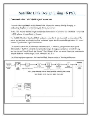
- 1. Satellite Link Design Using 16 PSK Communication Lab- Mini ProjectChintan Joshi Phase-shift keying (PSK) is a digital modulation scheme that conveys data by changing, or modulating, the phase of a reference signal (the carrier wave). In this Mini Project, the link design in satellite communication is described and simulated. I have used 16-PSK scheme for modulation of the data. The 16-PSK Modulator Baseband block modulates using the 16-ary phase shift keying method. The output is a baseband representation of the modulated signal. The 16-ary number parameter, 16, is the number of points in the signal constellation. The block accepts scalar or column vector input signals. Alternative configurations of the block determine how the block interprets its input and arranges its output, as explained in the following sections.Integer-Valued Signals and Binary-Valued Signals. When you set the Input type parameter to Integer, the block accepts integer values between 0 and 16-1. The following figure represents the Simulink block diagram model of the designed system:
- 2. The Simulink Model of the satellite link contains following blocks: Bernoulli Binary Generator: The Bernoulli Binary Generator block generates random binary numbers using a Bernoulli distribution. We can generate random binary sequence using Bernoulli distribution with desired probability. 16PSK Modulator: The 16-PSK Modulator Baseband block modulates using the 16-ary phase shift keying method. The output is a baseband representation of the modulated signal. The 16-ary number parameter, 16, is the number of points in the signal constellation. Transmission Power, Antenna Gain: It ises the dB gain block from Math Functions - Math Operations . The dB Gain block multiplies the input by the decibel values specified in the Gain parameter. For an M-by-N input matrix u with elements uij, the Gain parameter can be a real M-by-N matrix with elements gij to be multiplied element-wise with the input, or a real scalar. Free Space Path Loss: The Free Space Path Loss block simulates the loss of signal power due to the distance between transmitter and receiver. The block reduces the amplitude of the input signal by an amount that is determined in either of two ways: 1) By the Distance (km) and Carrier frequency (MHz) parameters, if you specify Distance and Frequency in the Mode field 2) By the Loss (dB) parameter, if you specify Decibels in the Mode field This block accepts a column vector input signal. The input signal to this block must be a complex signal. Receiver Thermal Noise: The Receiver Thermal Noise block simulates the effects of thermal noise on a complex, baseband signal. You can specify the amount of thermal noise in three ways, according to which Specification method. Noise temperature specifies the noise in degrees kelvin.
- 3. AGC: Automatic gain control (AGC) is an adaptive system in which average output signal level is fed back to adjust the gain to an appropriate level for a range of input signal levels. In AGC, weaker signals receive more gain and stronger signals receive less gain. 16-PSK Demodulator: The 16-PSK Demodulator Baseband block demodulates a signal that was modulated using the 16-ary phase shift keying method. The input is a baseband representation of the modulated signal. The input and output for this block are discrete-time signals. This block accepts a scalar-valued or column vector input signal. Error Rate Calculation: The Error Rate Calculation block compares input data from a transmitter with input data from a receiver. It calculates the error rate as a running statistic, by dividing the total number of unequal pairs of data elements by the total number of input data elements from one source. We can use this block to compute either symbol or bit error rate, because it does not consider the magnitude of the difference between input data elements. If the inputs are bits, then the block computes the bit error rate. If the inputs are symbols, then it computes the symbol error rate. Result: Carrier Freq: 1000MHz Carrier Freq: 5000MHz Carrier Freq: 10000MHz Conclusion PSK technique is widely used in digital communication. Here I have designed it’s one of the application using Simulink. In this mini project, link design in geostationary satellite communication using 16 PSK is designed and simulated. During simulation it is observed that operating frequency is very important parameter. as we increase carrier frequency, the probability of error increases rapidly.