

Empfohlen
Weitere ähnliche Inhalte
Was ist angesagt?
Was ist angesagt? (20)
Andere mochten auch
Andere mochten auch (20)
Ähnlich wie Computer networks--osi model
Ähnlich wie Computer networks--osi model (20)
Computer networks--osi model
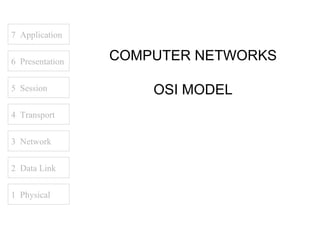
- 1. 7 Application 6 Presentation COMPUTER NETWORKS 5 Session OSI MODEL 4 Transport 3 Network 2 Data Link 1 Physical
- 2. 7 Application 6 Presentation Source 1. Computer Networks, Andrew S. 5 Session Tanenbaum 2. www.cisco.com 3. www.novell.com 4 Transport 4. www.rad.com 5. www.3com.com 3 Network 2 Data Link 1 Physical
- 3. 7 Application 6 Presentation 5 Session 4 Transport INTRODUCTION 3 Network 2 Data Link 1 Physical
- 4. 7 Application NETWORK GOALS 6 Presentation The two main benefits of networking computers are… Communications 5 Session Information can be distributed very quickly, such as email and video conferencing. 4 Transport Saving Money Resources such as information, software, and 3 Network hardware can be shared. 2 Data Link CPUs and hard disks can be pooled together to create a more powerful machine. 1 Physical
- 5. 7 Application APPLICATIONS 6 Presentation A lot of things we take for granted are the result of computer networks. 5 Session • Email • Chat • Web sites 4 Transport • Sharing of documents and pictures • Accessing a centralized database of information 3 Network • Mobile workers 2 Data Link 1 Physical
- 6. 7 Application NETWORK STRUCTURE 6 Presentation The subnet interconnects hosts. Subnet 5 Session Carries messages from host to host. It is made up of telecommunication lines (i.e. circuits, channels, 4 Transport trunks) and switching elements (i.e. IMPs, routers). Hosts 3 Network End user machines or computers. 2 Data Link Q: Is the host part of the subnet? 1 Physical
- 7. 7 Application NETWORK ARCHITECTURES 6 Presentation A set of layers and protocols is called the network architecture. 5 Session 1. Protocol Hierarchies Networks are organized as layers to reduce design 4 Transport complexity. Each layer offers services to the higher layers. Between adjacent layers is an interface. 3 Network Services – connection oriented and connectionless. 2 Data Link Interface – defines which primitives and services the lower layer will offer to the upper layer. 1 Physical Primitives – operations such as request, indicate, response, confirm.
- 8. 7 Application NETWORK ARCHITECTURES 6 Presentation 2. Design Issues for the Layers • Mechanism for connection establishment • Rules for data transfer 5 Session • Error control • Fast sender swamping a slow receiver 4 Transport • Inability of processes to accept long messages • Routing in the case of multiple paths 3 Network 2 Data Link 1 Physical
- 9. 7 Application OSI REFERENCE MODEL 6 Presentation The Open Systems Interconnection is the model developed by the International Standards Organization. 5 Session Benefits 4 Transport • Interconnection of different systems (open) • Not limited to a single vendor solution 3 Network Negative Aspect • Systems might be less secure 2 Data Link • Systems might be less stable 1 Physical
- 10. 7 Application OSI REFERENCE MODEL 6 Presentation 1. Physical Layer a) Convert the logical 1’s and 0’s coming from layer 2 into electrical signals. 5 Session b) Transmission of the electrical signals over a communication channel. 4 Transport Main topics: 3 Network • Transmission mediums • Encoding 2 Data Link • Modulation • RS232 and RS422 standards • Repeaters 1 Physical • Hubs (multi-port repeater)
- 11. 7 Application OSI REFERENCE MODEL 6 Presentation 2. Data Link Layer a) Error control to compensate for the imperfections of the physical layer. 5 Session b) Flow control to keep a fast sender from swamping a slow receiver. 4 Transport Main topics: 3 Network • Framing methods • Error detection and correction methods 2 Data Link • Flow control • Frame format • IEEE LAN standards 1 Physical • Bridges • Switches (multi-port bridges)
- 12. 7 Application OSI REFERENCE MODEL 6 Presentation 3. Network Layer a) Controls the operation of the subnet. 5 Session b) Routing packets from source to destination. c) Logical addressing. 4 Transport Main topics: 3 Network • Internetworking • Routing algorithms • Internet Protocol (IP) addressing 2 Data Link • Routers 1 Physical
- 13. 7 Application OSI REFERENCE MODEL 6 Presentation 4. Transport Layer a) Provides additional Quality of Service. 5 Session b) Heart of the OSI model. Main topics: 4 Transport • Connection-oriented and connectionless services • Transmission Control Protocol (TCP) 3 Network • User Datagram Protocol (UDP) 2 Data Link 1 Physical
- 14. 7 Application OSI REFERENCE MODEL 6 Presentation 5. Session Layer a) Allows users on different machines to establish sessions between them. 5 Session b) One of the services is managing dialogue control. 4 Transport c) Token management. 3 Network d) Synchronization. 2 Data Link 1 Physical
- 15. 7 Application OSI REFERENCE MODEL 6 Presentation 6. Presentation Layer a) Concerned with the syntax and semantics of the information. 5 Session b) Preserves the meaning of the information. 4 Transport c) Data compression. d) Data encryption. 3 Network 2 Data Link 1 Physical
- 16. 7 Application OSI REFERENCE MODEL 6 Presentation 7. Application Layer a) Provides protocols that are commonly needed. 5 Session Main topics: • File Transfer Protocol (FTP) 4 Transport • HyperText Transfer Protocol (HTTP) • Simple Mail Transfer Protocol (SMTP) 3 Network • Simple Network Management Protocol (SNMP) • Network File System (NFS) • Telnet 2 Data Link 1 Physical
- 17. 7 Application SERVICES 6 Presentation Each layer provides services to the layer above it. 1. Terminologies 5 Session Entities – active elements in each layer (e.g. process, intelligent I/O chip). 4 Transport Peer Entities – entities in the same layer on different machines. 3 Network Service Provider – Layer N. Service User – Layer N + 1. 2 Data Link Service Access Points – places where layer N + 1 can access services offered by layer N. 1 Physical
- 18. 7 Application SERVICES 6 Presentation 2. Connection-Oriented and Connectionless Connection-Oriented – before data is sent, the service from the sending computer must establish 5 Session a connection with the receiving computer. 4 Transport Connectionless – data can be sent at any time by the service from the sending computer. 3 Network Q: Is downloading a music file from the Internet connection-oriented or connectionless? 2 Data Link Q: Is email connection-oriented or connectionless? 1 Physical
- 19. 7 Application SERVICES 6 Presentation 3. Service Primitives Request – entity wants the service to do some work 5 Session Indicate – entity is to be informed about an event 4 Transport Response – entity responds to an event Confirm – entity is to be informed about its request 3 Network Sending Computer Receiving Computer 2 Data Link 4 Transport 4 Transport 1. request 4. confirm 2. indicate 3. response 1 Physical 3 Network 3 Network
- 20. 7 Application BANDWIDTH 6 Presentation The capacity of the medium to transmit data. Analog Bandwidth 5 Session • Measurement is in Hertz (Hz) or cycles/sec. 4 Transport Digital Bandwidth • Measurement is in bits per second (bps). 3 Network Q: Is 100MHz = 100Mbps? 2 Data Link Q: Is 100Mbps = 100MBps? 1 Physical
- 21. Hello 7 Application AH Hello 6 Presentation PH AH Hello 5 Session SH PH AH Hello 4 Transport TH SH PH AH Hello 3 Network NH TH SH PH AH Hello 2 Data Link DH NH TH SH PH AH Hello DT 1 Physical Bits
- 22. 7 Application 6 Presentation 5 Session 4 Transport PHYSICAL LAYER 3 Network 2 Data Link 1 Physical
- 23. 7 Application OVERVIEW 6 Presentation 1. Signals • Fourier analysis • Maximum data rate of a channel 5 Session 2. Transmission Media • Guided and Unguided 4 Transport 3. Analog Transmission • Modulation • Modems 3 Network • RS-232, RS-422 4. Digital Transmission • Encoding schemes 2 Data Link • Repeaters and hubs 5. Transmission and Switching 1 Physical • Multiplexing (FDM and TDM) • Circuit vs. packet switching
- 24. 7 Application SIGNALS 6 Presentation 1. Fourier Analysis a) All signals can be represented mathematically. 5 Session b) A periodic function can be constructed by adding a number of sine and cosine functions. 4 Transport Fundamental frequency – where f = 1/T Harmonics – integer multiples of the fundamental 3 Network frequency Baud – number of signal level changes per second 2 Data Link Q: Is baud and data rate different terms? 1 Physical Q: Is 1 baud equal to 1bps?
- 25. 7 Application SIGNALS 6 Presentation 2. Maximum Data Rate of a Channel Nyquist Maximum data rate = 2H log2V (bits/sec) 5 Session H = line bandwidth V = a signal with V discrete levels 4 Transport Example: 3 Network A noiseless 3kHz channel cannot transmit binary (2 level) signals at a rate faster than 6000bps 2(3k) log22 = 6000bps 2 Data Link logAV = (1 / ln A) ln V 1 Physical
- 26. 7 Application SIGNALS 6 Presentation Shannon Maximum data rate (bits/sec) = H log2(1+ PS/PN) H = line bandwidth 5 Session PS = signal strength in watts PN = noise strength in watts 4 Transport Example: A 3kHz channel with a noise ratio of 30dB 3 Network (PS/PN = 1000) cannot transmit at a rate faster than 30,000bps 2 Data Link (3k) log2(1001) = 30,000bps 1 Physical Note: SNR = 10log10(PS/PN)
- 27. 7 Application SIGNALS 6 Presentation 3. Attenuation vs. Amplification Attenuation The signal received is weaker than the signal sent. 5 Session Attenuation (dB) = 10log10(P1/P2) 4 Transport Amplification The signal received is stronger than the signal 3 Network sent. Amplification (dB) = 10log10(P2/P1) 2 Data Link Note: P1 = transmitted signal power in watts 1 Physical P2 = received signal power in watts Q: If the result of the attenuation formula is negative, what happened to the signal?
- 28. 7 Application TRANSMISSION MEDIA 6 Presentation 1. Guided Data is sent via a wire or optical cable. 5 Session Twisted Pair Two copper wires are twisted together to reduce the effect of crosstalk noise. (e.g. Cat5, UTP, STP) 4 Transport Baseband Coaxial Cable 3 Network A 50-ohm cable used for digital transmission. Used in 10Base2 and 10Base5. 2 Data Link Broadband Coaxial Cable A 75-ohm cable used for analog transmission such 1 Physical as Cable TV.
- 29. 7 Application TRANSMISSION MEDIA 6 Presentation Fiber Optic Cables Two general types are multimode and single mode. 5 Session In multimode, light is reflected internally. Light source is an LED. 4 Transport 3 Network In single mode, the light propagates in a straight line. Light source come from expensive laser 2 Data Link diodes. Faster and longer distances as compared to multimode. 1 Physical * Fiber optic cables are difficult to tap (higher security) and are normally used for backbone cabling.
- 30. 7 Application TRANSMISSION MEDIA 6 Presentation 2. Unguided Data is sent through the air. 5 Session Line-of-sight Transmitter and receiver must “see” each other, 4 Transport such as a terrestrial microwave system. Communication Satellites 3 Network A big microwave repeater in the sky. Data is broadcasted, and can be “pirated.” 2 Data Link Radio Term used to include all frequency bands, such as 1 Physical FM, UHF, and VHF television.
- 31. 7 Application ANALOG TRANSMISSION 6 Presentation 1. Modulation Modulating a sine wave carrier to convey data. 5 Session Amplitude Modulation (AM) Amplitude is increased/decreased while frequency 4 Transport remains constant. Frequency Modulation (FM) 3 Network Frequency is increased/decreased while amplitude remains constant. 2 Data Link Phase Modulation Wave is shifted, while amplitude and frequency 1 Physical remains constant.
- 32. 7 Application ANALOG TRANSMISSION 6 Presentation 2. Modems A device that accepts digital signals and outputs a modulated carrier wave, and vice versa. 5 Session It is used to interconnect the digital computer to the 4 Transport analog telephone network. * Modems for PC’s can be external or internal. 3 Network * Nokia makes modems for leased line connections. 2 Data Link 1 Physical
- 33. 7 Application ANALOG TRANSMISSION 6 Presentation 3. RS-232 and RS-449 Two well known physical layer standards. 5 Session RS-232 • 20 kbps 4 Transport • Cables up to 15 meters • Unbalanced transmission (common ground) 3 Network RS-422 2 Data Link • 2 Mbps at 60 meters • 1 Mbps at 100 meters • Balanced transmission (a pair of wires for Tx, Rx) 1 Physical
- 34. 7 Application DIGITAL TRANSMISSION 6 Presentation 1. Encoding Schemes Converting logical data into electrical signals suitable for transmission. 5 Session Manchester 4 Transport • Mid bit transition for clock synchronization and data • Logic 0 = high to low transition 3 Network • Logic 1 = low to high transition 2 Data Link Differential Manchester • Mid bit transition for clock synchronization only 1 Physical • Logic 0 = transition at the beginning of each bit period • Logic 1 = no transition at the beginning of each bit period
- 35. 7 Application DIGITAL TRANSMISSION 6 Presentation 2. Repeaters and Hubs These are physical layer devices. 5 Session Repeaters • Restores the strength of an attenuated signal. 4 Transport • Used to increase the transmission distance. • Does not filter data traffic. 3 Network Hubs • Multi-port repeater. 2 Data Link • Interconnects several computers. • Does not filter data traffic. 1 Physical * Picture from 3com.com
- 36. 7 Application 6 Presentation 5 Session 4 Transport NETWORK LAYER 3 Network 2 Data Link 1 Physical
- 37. 7 Application OVERVIEW 6 Presentation 1. Routing Algorithms • Shortest Path • Flooding 5 Session • Flow-based • Distance Vector • Link State 4 Transport • Hierarchical • Broadcast 3 Network • Multicast • Routing for Mobile Hosts 2 Data Link 2. Congestion control 3. IP Addressing 4. Routers 1 Physical
- 38. 7 Application ROUTING ALGORITHMS 6 Presentation 1. Shortest Path B(A,2) C(B,3) 5 Session B 1 C 2 4 Transport A(-,-) 3 2 3 D(E,3) 2 A F(E,4) 3 Network D 1 1 F E(A,2) 2 2 Data Link 2 E 1 Physical A–E–D–F A – E – F is the answer.
- 39. 7 Application ROUTING ALGORITHMS 6 Presentation 2. Flooding Packet to IMP C 5 Session Packet IMP Packet to IMP D 4 Transport B Packet to IMP E To prevent packets from circulating indefinitely, a 3 Network packet has a hop counter. Every time a packet arrives at an IMP, the hop counter is decrease by 1. Once the 2 Data Link hop counter of a packet reaches 0, the packet is discarded. 1 Physical
- 40. 7 Application IP ADDRESSING 6 Presentation Format xxxxxxxx.xxxxxxxx.xxxxxxxx.xxxxxxxx where x is either 0 or 1 5 Session Example 1: 4 Transport 11111111. 11111111.00000000.00000000 255.255.0.0 3 Network Example 2: 2 Data Link 11111111. 11111111.10000000.00000000 1 Physical 255.255.192.0
- 41. 7 Application IP ADDRESSING 6 Presentation Network Address Example 1: 5 Session IP address of computer 180.100.7.1 Mask 255.255.0.0 Network address 180.100.0.0 4 Transport Example 2: 3 Network IP address of computer 180.100.7.1 Mask 255.255.255.0 2 Data Link Network address 180.100.7.0 Example 3: 1 Physical IP address of computer 180.100.7.2 Mask 255.255.192.0 Network address 180.100.0.0
- 42. 7 Application IP ADDRESSING 6 Presentation Mask Valid mask are contiguous 1’s from left to right. 5 Session Examples: 4 Transport Valid 255.0.0.0 255.255.0.0 3 Network 255.255.255.0 2 Data Link Invalid 255.1.0.0 255.0.255.0 1 Physical 255.255.64.0 200.255.0.0
- 43. 7 Application IP ADDRESSING 6 Presentation Subnets The Internet is running out of IP address. One solution is to subnet a network address. 5 Session This is done by borrowing host bits to be used as 4 Transport network bits. Example: 3 Network Class B mask 255.255.0.0 Borrowing 1 bit gives a subnet mask of 255.255.128.0 2 Data Link Borrowing 2 bits gives a subnet mask of 255.255.192.0 Borrowing 3 bits gives a subnet mask of 255.255.224.0 Borrowing 4 bits gives a subnet mask of 255.255.240.0 1 Physical
- 44. 7 Application IP ADDRESSING 6 Presentation Example: Given an IP address of 180.200.0.0, subnet by borrowing 4 bits. 5 Session Subnet mask = 255.255.240.0 4 Transport The 4 bits borrowed are value 128, 64, 32, 16. This will create 16 sub networks, where the first and last will be unusable. 3 Network Sub network address: 2 Data Link 180.200.0.0 180.200.16.0 180.200.32.0 1 Physical 180.200.48.0 180.200.64.0 etc…
- 45. 7 Application IP ADDRESSING 6 Presentation The first 3 usable sub networks are: 180.200.16.0 180.200.32.0 5 Session 180.200.48.0 4 Transport For sub network 180.200.16.0, the valid IP address are: 3 Network 180.200.16.1 to 180.200.31.254 2 Data Link Directed broadcast address is: 180.200.31.255 1 Physical
- 46. 7 Application ROUTERS 6 Presentation A layer 3 device that is used to interconnect 2 or more logical networks. 5 Session Can filter broadcast traffic, preventing broadcast traffic from one network from reaching another network. 4 Transport 3 Network 180.200.0.0 202.5.3.0 2 Data Link 1 Physical