
Empfohlen
Weitere ähnliche Inhalte
Was ist angesagt?
Was ist angesagt? (20)
Ähnlich wie Inverter
Ähnlich wie Inverter (20)
Kürzlich hochgeladen
Kürzlich hochgeladen (20)
Inverter
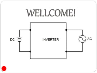
- 1. WELLCOME! 1
- 2. WORKING MECHANISM OF POWER INVERTER 2 Oct, 2018 By: Sayed Ahmad Zamir Kandahar University Engineering faculty Energy engineering Department
- 3. Outline 1. Introduction 2. Inverter 3. AC as an output 4. Working mechanism 5. AC as Sinusoidal 6. SPWM Technique 7. Transistor 8. Comparator 9. Inductor and capacitor filtration 10. Old method of conversion 11. Types of power inerter 12. Inverter vs. Converter and UPS 3
- 4. Introduction There are two types of power in the world an AC and DC. A DC current is that which has one direction of flowing current or does not have a frequency, While AC current has a frequency and changes the direction of the flowing current our the time. 4
- 5. Cont. Although they have their own application, but some time we need to convert them on each other. To convert the DC into AC, we use an inverter. 5
- 6. inverter All of us are familiar with an inverter, and we have been using it in our daily life. An inverter is a electrical circuit capable of turning DC power in to an AC power statically, while at the same time regulating the voltage, current and frequency the signal. 6
- 7. Cont. 7
- 8. AC as an output The average value of AC power is zero In fact all inverters are produce a square wave power. 8
- 9. Working mechanism To convert a DC power into an AC power, lets to look this circuit which is called full bridge inverter. This circuit consist of four switches. The output is on the load. 9
- 10. Cont. In first stage the S1 and S4 is on. The current flow from positive to negative on one direction. 10
- 11. Cont. 11
- 12. Cont. In the second stage if we switch on the S3 and S2, the result the current is flowing from positive to negative but, the opposite direction of as in first stage without to change the direction of source. 12
- 13. Cont. 13
- 14. Cont. The result is that, here we applied the voltage on the load but the direction of the current was different and the applied voltage on the load was changed from positive to negative. 14
- 15. Cont. If switch once the all switches respectively, here will be produced one cycle of an AC current. If we want to produce a power of 50HZ frequency, we have to switch on the S1 and S4 for 1/100 second, and then switch on S3 and S4 for 1/100 second, which is so difficult. 15
- 16. Cont. For half positive voltage For half negative voltage 16
- 17. Cont. To make this switches on and of at this much high frequency, we require an electronic based controller circuit. This may be analog or digital electronic circuit, which generate the current pulses for this switches. 17
- 18. AC as Sinusoidal The actual alternating current should have form of sinusoidal wave, whose magnitude increases and decreases. 18
- 19. Cont. But our out pout is a square wave form. 19
- 20. SPWM Technique To regulate this square wave form as sinusoidal, a technique is used which is called Sinusoidal Pulse Width Modulation (SPWM). There is the need to change the width of pulses, means to vary the on time of the switches.20
- 21. Cont. Firstly they are may on for a very small duration, then their on time may to increase and then it may to decrease at the same rate. 21
- 22. Cont. To do this for half positive cycle, do not turn on T1 and T4 for the complete time. Thy must on and off. 22
- 23. Cont. For half negative cycle T3 and T4 on and off, like T1 and T4. 23
- 24. Cont. The output voltage is positive and negative, and the width of pulses are very short as compere to the response time of the load circuit. The average value of these pulses will be the sinusoidal nature. 24
- 25. Cont. The transistors are to be used as four switches to on and off the circuit. To average the square waves form to sinusoidal form, two comparator must be used. 25
- 26. Transistor To on and of the switches as much this high frequency, the Transistors must be used. Transistor is a device made from semiconductor as silicon and has a capability to switch on and off rapidly. 26
- 27. Cont. Has two types PNP NPN PNP means positive negative and positive. NPN means negative positive and negative. 27
- 28. comparator Comparator is a device which compere the given voltage to the reference voltage. Has many types and we use this for averaging the output voltage of SPWM. 28
- 29. Cont. They are also arranging the (on and of) of transistor to avid the short circuit. It means that when the S1 is on the S2 must be off, and also while the S3 is on the S4 must be off. 29
- 30. Inductor and capacitor filtration An inductor is a device which conserve energy in the magnetic field. And in an inverter it is used for current filtration. A capacitor is a device which conserve energy in an electric filed. And in it is used for voltage filtration. 30 Capacit or Inductor
- 31. Stepping up the voltage To step up the inverted voltage commonly from 12 voltsto 220 volts, we use a transformer. 31
- 32. Old method of conversion In the past the changing of current was had been done dynamically before the invention of inverter by connecting of the DC motor with an AC generator. Rotary switch. Which were not efficient. 32
- 33. Types of power inverter I. The square wave inverter: a square wave inverter is a one of simplest inverter type, which convert a straight dc signal to a phase shifting ac signal, but the output is not pure ac, i.e. in the form of a pure sine wave, but it’s a square wave. 33
- 34. Cont. II. The modified sine wave inverter: a modified sine wave shows some pauses before the phase shifting of the wave, i.e. unlike a square it does not shift it phase abruptly from positive to negative, or unlike a sine wave does not make a smooth transition from positive to negative but brief pauses and them shifts it’s phase. 34
- 35. Cont. Pure sine wave inverter: the electrical circuit of a pure sine wave inverter is more complex than a square wave or modified sine waver inverter. Another way to obtain a sine output is to obtain a square wave output from a square wave and then modify this output to achieve a pure sine wave 35
- 36. Inverter vs. Converter and UPS Converters and inverters are electrical devices that both convert power. Converters convert the voltage of an electric device, usually alternating current (AC) to direct current (DC). On the other hand, inverters convert direct current (DC) to alternating current (AC). UPS: Uninterruptible power supply (UPS) provides power in case of power cut. Mostly used for desktop computers backup and can save energy for computer from 10 to 20 minutes. 36
- 39. How much do you specify from my presentation? 40% 60% 80% 100% Thank 39