High Sensitivity Sanger Sequencing for Minor Variant Detection

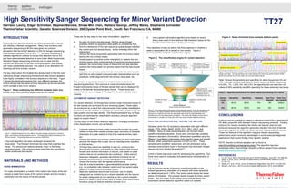
Detecting minor genetic variants has become essential to cancer and infectious disease management. Many have turned to next generation sequencing to fill this need given the common perception that the limit of detection (LOD) for Sanger sequencing is somewhere between 15% to 25%1,2,3. We have discovered a software algorithmic solution to reduce this detection limit to 5% and have demonstrated detection at even lower allele frequencies. Standard Sanger sequencing protocols can be used and the method can generate the familiar electropherogram data display with noise substantially reduced. This opens up an alternative for detecting low level somatic variants. The key observation that enabled this development is that the noise underlying Sanger sequencing fluorescence data (traces) appears to be highly correlated to the primary sequence in the data. Figure 1 shows the electropherograms from two different samples: the control sample has the same primary sequence as the test sample which contains a few minor variants.
Empfohlen

Empfohlen
Weitere ähnliche Inhalte
Was ist angesagt?
Was ist angesagt? (20)
Andere mochten auch
Andere mochten auch (10)
Ähnlich wie High Sensitivity Sanger Sequencing for Minor Variant Detection
Ähnlich wie High Sensitivity Sanger Sequencing for Minor Variant Detection (20)
Mehr von Thermo Fisher Scientific
Mehr von Thermo Fisher Scientific (20)
Kürzlich hochgeladen
Kürzlich hochgeladen (20)
High Sensitivity Sanger Sequencing for Minor Variant Detection
- 1. Harrison Leong, Edgar Schreiber, Stephan Berosik, Shiaw-Min Chen, Wallace George, Jeffrey Marks, Stephanie Schneider ThermoFisher Scientific, Genetic Sciences Division, 200 Oyster Point Blvd., South San Francisco, CA, 94080 RESULTS Table 1 shows the sensitivity and specificity for allele frequencies 5% and 10%. Although we have been able to detect variants at allele frequencies 0.6125%, 1%, 1.25%, 2%, and 2.5%, the algorithm did not meet the LOD criteria of 95% sensitivity and 99% specificity for these extremely low levels. INTRODUCTION Detecting minor genetic variants has become essential to cancer and infectious disease management. Many have turned to next generation sequencing to fill this need given the common perception that the limit of detection (LOD) for Sanger sequencing is somewhere between 15% to 25%1,2,3. We have discovered a software algorithmic solution to reduce this detection limit to 5% and have demonstrated detection at even lower allele frequencies. Standard Sanger sequencing protocols can be used and the method can generate the familiar electropherogram data display with noise substantially reduced. This opens up an alternative for detecting low level somatic variants. The key observation that enabled this development is that the noise underlying Sanger sequencing fluorescence data (traces) appears to be highly correlated to the primary sequence in the data. Figure 1 shows the electropherograms from two different samples: the control sample has the same primary sequence as the test sample which contains a few minor variants. CONCLUSIONS It should now be possible to achieve a reference-based limit of detection of 5% allelic proportion with standard Sanger sequencing protocols. Existing protocols for visually reviewing the results can also be used and are enhanced because the algorithm generates results in the form of familiar electropherograms for which the noise has been substantially diminished. These two features of the algorithm may give Sanger sequencing performance and/or economic advantages in some molecular diagnostic applications that require finding minor genetic variants. NOTE: Results on clinical samples can be found at www.thermofisher.com/sangeroncology. The algorithm has been embedded within ThermoFisher Scientific’s Minor Variant Finder software (www.thermofisher.com/mvf ). REFERENCES 1. Lin, M.T. et al. (2014), American Journal of Clinical Pathology, June 2014; 141:856-866. 2. Jancik, S. et al. (2012), Journal of Experimental & Clinical Cancer Research 2012; 31:79:1-13. 3. Tsiatis, A.C. et al. (2010), Journal of Molecular Diagnostics, July 2010; 12:4:425-432. 4. Wang G. and Guo L. (2013) Journal of Applied Mathematics, 2013; article 696491. High Sensitivity Sanger Sequencing for Minor Variant Detection Thermo Fisher Scientific • 5781 Van Allen Way • Carlsbad, CA 92008 • thermofisher.com TT27 These are the key steps in the noise minimization algorithm: a) for each of control and test traces, find the range of base positions where the sequence data quality is consistently high; b) find the intersection of the high-sequence-quality ranges between the control and test sample traces; do the following within that intersection: c) remove the trace components associated with the primary bases leaving the non-primary traces; d) locally expand or contract and/or strengthen or weaken the non- primary traces of the control sample to maximize correspondence between the non-primary traces of the control and test samples; e) subtract the manipulated non-primary traces from the test sample traces; f) suppress non-primary peaks that are obviously not variant peaks (set them to zero) based on several peak characteristics such as amplitude, width, alignment with the primary trace peak, etc. This process is applied to traces from both forward and reverse sequencing reactions. The outcome is noise minimized traces for forward and reverse traces of the test sample that can be displayed for review in the familiar electropherogram format. These traces are passed into the second stage of the algorithm to automatically detect variants. AUTOMATED VARIANT DETECTION For variant detection, the forward and reverse noise-minimized traces of the test sample are examined for any remaining peaks. These peaks are scrutinized by a set of five interconnected multi-variate classification functions to decide whether or not there is a bona fide variant at a given base position and its base identity. The final thresholds of four of these functions are optimized for classification accuracy using an algorithm based on swarm theory 4. DATA FOR DEVELOPING AND TESTING THE METHOD Samples came from 22 amplicons associated with eight different genes: TP53, KRAS, BRAF, EGFR, FLT3, RB1, CDH1, and ERBB2. Many of these were extracted from formalin-fixed, paraffin-embedded samples. Some were commercially available reference standards (Acrometrix), others were quantified using the RNase-P quantitative polymerase chain reaction assay and serially diluted. Allelic proportions spanned 0.6125% to 50%. These samples were amplified, sequenced, and pre-processed using standard protocols and tools for fluorescent dye terminator Sanger sequencing from Applied BiosystemsTM. A third of these data were used for developing the algorithms. Two thirds were used for evaluating the performance characteristics of the method. Figure 1. Noise underlying two different samples looks very similar when their primary sequences are the same. Control Sample Test Sample with Variants Figure 1: Electropherograms from two different physical samples showing the underlying noise; note the close similarity between the two. The bottom 200 relative fluorescence units (RFUs) is shown. The primary peaks are up at around 1000 RFUs. A two-part algorithm has been developed to exploit this observation. The first part minimizes the noise that underlies the traces. The second part detects variants, if any, in the noise- minimized traces. This communication describes the algorithmic details and shows test results. f) Use a global optimization algorithm (one based on swarm theory was used) to find optimum final threshold values for the four discriminant functions of step (c) and (e). The classifiers of step (e) deliver the final judgment on whether a peak is associated with a variant or non-variant. Figure 2 summarizes the complete classification engine. MATERIALS AND METHODS NOISE MINIMIZATION For noise minimization, a model of the noise in the traces of the test sample is made from traces of the control sample and this model is subtracted from the traces of the test sample. The key steps of the variant detection algorithm, including construction of the classification engine, are as follows: a) Compute metrics on trace peaks such as the location of a peak relative to that of the nearest primary base, symmetry of the peak, sharpness of a peak relative to that of its nearest primary base, etc.; b) Classify the largest non-primary peaks based on each peak metric alone to the degree that a peak can be unambiguously classified in this manner; c) Of those that cannot be classified in step (b), construct two discriminant functions, one based on peak metrics that combine forward and reverse information (x-strand), one based on peak metrics that do not combine the two (s-strand). Within each of these two categories, generate discriminant functions for all possible combinations of metrics belonging to the category and choose the function with the highest performance; d) Use the s-strand classifier to generate additional peak metrics; e.g., the probability ratio between variant and non-variant peaks based on s-strand pre-thresholded output; e) Make two additional discriminant functions: one for peaks categorized as variants by the x-strand classifier and the second for peaks categorized as non-variants by the x-strand classifier. Metrics of steps (c) and (d) are used to create these discriminant functions using the feature selection process of (c). INPUT DATA: Forward control Forward test Reverse control Reverse test Fwd and Rvs test, noise minimized Single-strand metrics: peak height, width, sharpness, symmetry, signal to noise, etc. Cross-strand metrics (combined fwd rvs information): base complementarity, relative peak amplitude, relative width, etc. Signal to noise outliers are variant candidates Classifier for clear cut cases Classifier based on cross-strand metrics Classifier to override cross-strand variant calls (all metrics) Classifier to override cross- strand non-variant calls (all metrics) OUTPUT RESULTS: Variant locations and base identities Meta-metrics from classifier based on single- strand metrics: var/non-var probability ratio, pre- thresholded score, etc. Figure 2. The classification engine for variant detection. Figure 2: Trace data enters at the upper left and detected variants, if any, are reported out at the bottom. The figure illustrates that the decision making process is layered so that easy decisions are made first and only the trace peaks that cannot be clearly classified are funneled down into the deeper levels of analysis. This allows the classifier at each level to concentrate on a smaller set of the data which may have a simpler statistical structure. Figure 3 shows results of applying noise minimization to the forward sequencing orientation of a sample with three variants at an allele frequency of 1.25%. The central panel shows the traces before minimization. The process clearly reveals the three variant peaks. The red marks in the bottom panel indicate where the automated variant detection algorithm called out variants. 1.25% Variant Test Sample Control Sample algorithm finds the variants KB Basecaller misses the variants 1.25% Test Sample, Noise Minimized Figure 3. Noise minimized trace example (bottom panel). Figure 3: Noise minimization reveals 1.25% minor variants deeply embedded in the noise underlying Sanger trace data. The high similarity in the noise between the control (top panel) and test (middle panel) traces allows much of the noise to be removed (bottom panel). TABLE 1: Algorithm performance for allele frequencies meeting LOD criteria Variant Level Sensitivity Specificity Datasets Total True Variants Total True Non-variants 5% 95.9% 99.8% 704 785 229623 10% 98.8% 99.8% 454 503 163037