Booking open Available Pune Call Girls Kirkatwadi 6297143586 Call Hot Indian...
Struds 2010(aug)
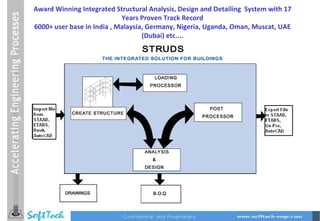
1. Award Winning Integrated Structural Analysis, Design and Detailing System with 17 Years Proven Track Record 6000+ user base in India , Malaysia, Germany, Nigeria, Uganda, Oman, Muscat, UAE (Dubai) etc....
4. Architectural import for structural plan tracing All layers from original CAD drawings are available for display and can be made on/ off as required – The Structural Designer has Architectural Plan view in the background and can draw structural model by tracing entities from imported CAD architectural drawing
5.
6. Modeling Features Curved Beam Inclined Beam Triangular Slab Rectangular Slab General Slab Straight beam
7.
8. Modeling Features L Shape Shearwall C Shape Shearwall L Shape Shearwall Circular Column T Shape Column L Shape Column Rectangular Column
9.
10. Modeling of industrial structures User defined steel Plane Trusses can be modeled and placed them on concrete frames
11. View Control Dynamic View Pan Rotate Rotate @ Z Zoom In Out Extents Pan Left Right Up Down View Point Iso Top Right Front
21. This constraint is used to simulate the condition when there is wide column. Due to the presence of the wide column the actual span of the beam is not the distance between the nodes but the distance between the outer edge of the wide column. So when there are wide columns then the actual stiffness of the beam will be more then when it is taken from node to node. On clicking Master-Slave relation we get the following dialog box. The Master Slave concept enables the creation of rigid links, using either the ‘Equal Degree of Freedom’ or the ‘Equal Displacement’ type of relationship Master Slave
22.
23.
24. Exports / Imports ETABS (*.$ET) File STRUDS model could be opened in ETABS to visualize the structure and also to perform analysis. ETABS model along with its analysis file could be imported in STRUDS for design and detailing. Export Import
44. Soft Storey Effect Soft Storeys can be defined. User should enter the factor, by which the end actions for all the members of this soft storey need to be modified. Due to this the beams at the upper and lower level, as well as the columns in between these two levels, will be designed for the elemental end forces obtained in the analysis multiplied by the factor, which you have specified. By default the factor is taken as 2.5
45. Facility to consider Vertical Seismic loads, for all the elements marked as Horizontal Cantilevers. The total seismic weight W, acting on the cantilever beam is given as, W = [Sum of all Elemental Dead loads] + [ (Live load reduction factor at the set floor level) * (sum of all Elemental Live Loads)] + [Dead load reaction of Cross Beam] + [(Live load reduction factor) * (Live load reaction of Cross Beam) ] This load is assumed to act at the center of the cantilever beam. The total design vertical seismic force is given as V = (10/3) * Ah * Total Seismic weight However, declaring these elements as cantilevers, will not affect the analysis results at all, and the cantilevering effect will be taken into account only at the design level. Vertical seismic load effects in horizontal cantilevers
49. PF1 PF2 PF3 PF1 Unit Load W1 W2 W3 h1 h2 h3 1 Q 1 Q 2 Q 3 Frame Stiffness Method K 1 = 1 / Δ 1 Similarly, K 2 = = 1 / Δ 2 , K 3 = = 1 / Δ 3 K = K 1 + K 2 + K 3 Distribution Factor DF 1 = K 1 / K V bPF1 = DF 1 x V bx Wh 2 = W 1 h 1 2 + W 2 h 2 2 + W 3 h 3 2 Q 1 = (W 1 h 1 2 / Wh 2 ) x V bPF1 Similarly base shear is calculated for Q 2 Q 3
51. Column Reaction Method Unit Load W1 W2 W3 h1 h2 h3 1 V b1 R1 R3 R5 R2 R4 R6 Q1 Q3 Q5 R = R 1 +R 2 + R 3 Distribution Factor DF 1 = R 1 /R Q 1 = DF 1 x V b1 Similarly the Q 2 ,Q 3 ,Q 4 ,Q 5 and Q 6 is calculated Wh 2 = W 1 h 1 2 + W 2 h 2 2 + W 3 h 3 2 V b1 = (W 1 h 1 2 / Wh 2 ) x V bx Similarly base shear is calculated for V b2 V b3
58. Wind load generation by Framing Method W1 W2 W3 h1 h2 h3 X 1 X 2 Y 1 Y 2 W 1X W 2X W 3X K = K 1 * K 2 * K 3 V z = V b * K P z = 0.6 * V z * V z W 1x = [Y 1 / 2 * (( h 1 / 2) + ( h 2 / 2))] * P z W 2x = [((Y 1 / 2 ) + (Y 2 / 2 )) * ((h 1 / 2) + (h 2 / 2))] * P z W 1y = [X 1 / 2 * (( h 1 / 2 ) + ( h2 / 2 ))] * P z W 2y = [((X 1 / 2 ) + (X 2 / 2 )) * (( h 1 / 2) + (h 2 / 2 ))] *P z Similarly Wind Load on all frames and all floors is calculated
60. Floor2 Floor3 h1 h2 h3 Floor1 X 1 Length Y 1 W 1X M X 1 / 2 Y 1 / 2 W 1y Floor1 K = K 1 * K 2 * K 3 V z = V b * K P z = 0.6 * V z * V z Total wind load on floor 1- W 1x = (Y 1 * ( h 1 / 2 ) + Y 1 * ( h 2 / 2)) * P z Total wind load on floor 1- W 1 y = (X 1 * ( h 1 / 2 ) + X 1 * ( h 2 / 2)) * P z Similarly Wind load on floor 2 and 3 is calculated in X and Y direction. This load is transferred to all column and shear wall nodes through diaphragm action. Wind load generation by Notional Method
63. Finite Element Analysis meshing of Slabs as shell element (Beta release) Discretization of Surfaces using Intelligent Free Mesh Algorithm – 6 Noded Triangular Finite Elements Considered
64.
65. View Surface element results in Post Processor Contour Diagrams (Filled & Vector) are produced for All Stresses and Displacements With Value table. Colors are graded from Maximum to Minimum
75. Auto CAD Output (DXF) drawing settings Following things can be done using this dialog box. 1. Color of any layer in drawing 2. Font of lettering 3. Line type 4. Layer on / off 5. Can create library of settings to implement in all other projects
82. Beam Design (Ductile Detailing clauses implemented) Detailing Provisions as per IS 13920:1993 6.1 General : Clause 6.1.1 : Factored Axial stress on the member under Eq loading shall not exceed 0.1 f ck Clause 6.1.2 : Width to Depth Ratio should be more than 0.3 Clause 6.1.3 : Width of the member shall not be less than 200 mm Clause 6.1.4 : Provided Depth of the beam shall preferably be not more than 1/4 of clear span
83. 6.2 Longitudinal Reinforcement : Clause 6.2.1 : Minimum tension steel ratio on any face at any section = 0.24 x √ (fck)/fy Clause 6.2.2 : Provided Maximum tension steel ratio on any face at any section shall not exceed 0.025 Clause 6.2.3 : The positive steel at a joint face must be at least equal to half the negative steel at that face. Clause 6.2.4 : The steel provided at each of the top and bottom face of the member at any section along its length shall be at-least equal to one fourth of the maximum negative moment steel provided at the face of either joint.
84.
85. Clause 6.3.5 : 6.3.5.a: Stirrup spacing over a length 2d at either end of a beam shall not exceed a) d/4 , b) 8 x smallest longitudinal dia. however it shall not be less than 100mm. 6.3.5.b.: Stirrup spacing in the rest portion <= d/2
92. As per IS 13920:1993 Clause 7.1.2 , The minimum dimension of column shall not be less than 200 mm. For the columns with unsupported length exceeding 4 m , the shortest dimension of the column shall not be less than 300 mm. As per IS 13920:1993 Clause 7.1.3 of IS 13920:1993, The ratio of the shortest cross sectional dimensions to the perpendicular dimension shall preferably not be less than 0.4. Transverse Reinforcement: As per IS 13920 : 1993,the design shear force for columns shall be the maximum of i) Calculated factored shear force as per analysis, and ii) A factored shear force given by Vu = 1.4 x (MubL,lim + MubR,lim)/storey height where MubL,lim,MubR,lim are moments of resistance, of opposite sign framing into the column from opposite faces (to be calculated as per IS 456 : 1978) Column Design (Ductile Detailing clauses implemented)
118. Thank You Soft – Tech Engineers Pvt. Ltd. The Pentagon, Unit 5A, Next to Satara Road telephone exchange, Shahu College Road, Pune – 411 009 Off.: +91-20-24217676, 24218747 Site : www.softtech-engr.com Email: sepl@softtech-engr.com