Osi reference model
•Als PPT, PDF herunterladen•
2 gefällt mir•539 views

Network Reference Models, OSI Reference Models, Upper Layers, Lower Layers

Empfohlen
Weitere ähnliche Inhalte
Was ist angesagt?
Was ist angesagt? (20)
Ähnlich wie Osi reference model
Ähnlich wie Osi reference model (20)
Mehr von Sagar Gor
Kürzlich hochgeladen
Kürzlich hochgeladen (20)
Osi reference model
- 2. Network Reference Models A computer network connects two or more devices together to share information and services. Multiple networks connected together form an internetwork. Internetworking present challenges - interoperating between products from different manufacturers requires consistent standards. Network reference models were developed to address these challenges. A network reference model serves as a blueprint, detailing how communication between network devices should occur. The two most recognized network reference models are: •The Open Systems Interconnection (OSI) model •The Department of Defense (DoD) model Network models are organized into layers, with each layer representing a specific networking function. These functions are controlled by protocols, which are rules that govern end-to-end communication between devices. Protocols on one layer will interact with protocols on the layer above and below it, forming a protocol suite or stack. The TCP/IP suite is the most prevalent protocol suite, and is the foundation of the Internet.
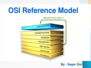
- 3. OSI Reference Model The Open Systems Interconnection (OSI) model was developed by the International Organization for Standardization (ISO), and formalized in 1984. It provided the first framework governing how information should be sent across a network. The OSI model consists of seven layers, each corresponding to a specific network function:
- 4. To remember (Please Do Not Throw Sausage Pizza Away) The OSI model itself is now somewhat deprecated – modern protocol suites, such as the TCP/IP suite, are difficult to fit cleanly within the OSI model’s seven layers. This is especially true of the upper three layers. The bottom (or lower) four layers are more clearly defined, and terminology from those layers is still prevalently used. Many protocols and devices are described by which lower layer they operate at. OSI Model - The Upper Layers The top three layers of the OSI model are often referred to as the upper layers: •Layer-7 - Application layer •Layer-6 - Presentation layer •Layer-5 - Session layer Protocols that operate at these layers manage application-level functions, and are generally implemented in software.
- 5. OSI Model - The Application LayerOSI Model - The Application Layer The Application layer (Layer-7)Application layer (Layer-7) provides the interface between the user application and the network. A web browser and an email client are examples of user applications. Examples of Application layer protocols include: •FTP, via an FTP client •HTTP, via a web browser •POP3 and SMTP, via an email client •Telnet The Application layer provides a variety of functions: •Identifies communication partners •Determines resource availability •Synchronizes communication
- 6. OSI Model - The Presentation Layer The Presentation layer (Layer-6)Presentation layer (Layer-6) controls the formatting and syntax of user data for the application layer. This ensures that data from the sending application can be understood by the receiving application. Standards have been developed for the formatting of data types, such as text, images, audio, and video. Examples of Presentation layer formats include: •Text - RTF, ASCII, EBCDIC •Images - GIF, JPG, TIF •Audio - MIDI, MP3, WAV •Movies - MPEG, AVI, MOV OSI Model - The Session Layer The Session layer (Layer-5)Session layer (Layer-5) is responsible for establishing, maintaining, and ultimately terminating sessions between devices. If a session is broken, this layer can attempt to recover the session. Sessions communication falls under one of three categories: •Full-Duplex – simultaneous two-way communication •Half-Duplex – two-way communication, but not simultaneous •Simplex – one-way communication
- 7. OSI Model - The Lower Layers The bottom four layers of the OSI model are often referred to as the lower layers: •Layer-4 – Transport layer •Layer-3 – Network layer •Layer-2 – Data-Link layer •Layer-1 – Physical layer Protocols that operate at these layers control the end-to-end transport of data between devices, and are implemented in both software and hardware. OSI Model - The Transport Layer The Transport layer (Layer-4)Transport layer (Layer-4) does not actually send data, despite its name. Instead, this layer is responsible for the reliable transfer of data, by ensuring that data arrives at its destination error-free and in order. Transport layer communication falls under two categories:
- 8. • Connection-oriented – requires that a connection with specific agreed-upon parameters be established before data is sent. • Connectionless – requires no connection before data is sent. Connection-oriented protocols provide several important services: • Segmentation and sequencing – data is segmented into smaller pieces for transport. Each segment is assigned a sequence number, so that the receiving device can reassemble the data on arrival. • Connection establishment – connections are established, maintained, and ultimately terminated between devices. • Acknowledgments – receipt of data is confirmed through the use of acknowledgments. Otherwise, data is retransmitted, guaranteeing delivery. • Flow control (or windowing) – data transfer rate is negotiated to prevent congestion. The TCP/IP protocol suite incorporates two Transport layer protocols: • Transmission Control Protocol (TCP) – connection-oriented • User Datagram Protocol (UDP) - connectionless
- 9. OSI Model - The Network Layer The Network layer (Layer-3)Network layer (Layer-3) controls internetwork communication, and has two key responsibilities: •Logical addressing – provides a unique address that identifies both the host, and the network that host exists on. •Routing – determines the best path to a particular destination network, and then routes data accordingly. Two of the most common Network layer protocols are: •Internet Protocol (IP) •Novell’s Internetwork Packet Exchange (IPX).
- 10. OSI Model - The Data-Link Layer While the Network layer is concerned with transporting data between networks, the Data-Link layer (Layer-2)Data-Link layer (Layer-2) is responsible for transporting data within a network. The Data-Link layer consists of two sublayers: •Logical Link Control (LLC) sublayer •Media Access Control (MAC) sublayer The Data-link layer packages the higher-layer data into frames, so that the data can be put onto the physical wire. This packaging process is referred to as framing or encapsulation. The encapsulation type will vary depending on the underlying technology. Common Data-link layer technologies include following: •Ethernet – the most common LAN data-link technology •Token Ring – almost entirely deprecated •FDDI (Fiber Distributed Data Interface) •802.11 Wireless •Frame-Relay •ATM (Asynchronous Transfer Mode)
- 11. OSI Model - The Physical Layer The Physical layer (Layer-1)Physical layer (Layer-1) controls the signaling and transferring of raw bits onto the physical medium. The Physical layer is closely related to the Data-link layer, as many technologies (such as Ethernet) contain both datalink and physical functions. The Physical layer provides specifications for a variety of hardware: •Cabling •Connectors and transceivers •Network interface cards (NICs) •Wireless radios •Hubs
- 12. Encapsulation and Layered Communication As data is passed from the user application down the virtual layers of the OSI model, each layer adds a header (and sometimes a trailer) containing protocol information specific to that layer. These headers are called Protocol Data Units (PDUs), and the process of adding these headers is called encapsulation. Note that in the TCP/IP protocol suite only the lower layers perform encapsulation, generally. For example, a Transport layer protocol such as TCP will add a header containing flow control, port numbers, and sequencing. The Network layer header contains logical addressing information, and the Data-link header contains physical addressing and other hardware specific information. Each layer communicates with the corresponding layer on the receiving device. For example, on the sending device, source and destination hardware addressing is placed in a Data-link header. On the receiving device, that Data-link header is processed and stripped away (decapsulated) before being sent up to the Network and other upper layers.
- 13. The PDU of each layer is identified with a different term: Network devices are commonly identified by the OSI layer they operate at; or, more specifically, what header or PDU the device processes. For example, switches are generally identified as Layer-2 devices, as switches process information stored in the Data-Link header of a frame, such as Ethernet MAC addresses. Similarly, routers are identified as Layer- 3 devices, as routers process logical addressing information in the Network header of a packet, such as IP addresses.
- 14. Encapsulation Illustrated The following illustrates how basic encapsulation occurs with the TCP/IP stack, which typically performs encapsulation only at the lower layers:
- 15. During encapsulation on the sending host: •Data from the user application is handed off to the Transport layer. •The Transport layer adds a header containing protocol-specific information, and then hands the segment to the Network layer. •The Network layer adds a header containing source and destination logical addressing, and then hands the packet to the Data-Link layer. •The Data-Link layer adds a header containing source and destination physical addressing and other hardware-specific information. •The Data-Link frame is then handed off to the Physical layer to be transmitted on the network medium as bits. During decapsulation on the receiving host, the reverse occurs: •The frame is received from the physical medium. •The Data-Link layer processes its header, strips it off, and then hands it off to the Network layer. •The Network layer processes its header, strips it off, and then hands it off to the Transport layer. •The Transport layer processes its header, strips it off, and then hands the data to the user application.
- 16. OSI Reference Model Example A web browser serves as a good practical illustration of the OSI model and the TCP/IP protocol suite: •Τhe web browser serves as the user interface for accessing a website. The browser itself does not function at the Application layer. Instead, the web browser invokes the Hyper Text Transfer Protocol (HTTP) to interface with the remote web server, which is why http:// precedes every web address. •The Internet can provide data in a wide variety of formats, a function of the Presentation layer. Common formats on the Internet include HTML, XML, PHP, GIF, and JPEG. Any encryption or compression mechanisms used on a website are also considered a Presentation layer function. •The Session layer is responsible for establishing, maintaining, and terminating the session between devices, and determining whether the communication is half-duplex or full-duplex. However, the TCP/IP stack generally does not include session-layer protocols, and is reliant on lower-layer protocols to perform these functions.
- 17. • HTTP utilizes the TCP Transport layer protocol to ensure the reliable delivery of data. TCP establishes and maintains a connection from the client to the web server, and packages the higher-layer data into segments. A sequence number is assigned to each segment so that data can be reassembled upon arrival. • The best path to route the data between the client and the web server is determined by IP, a Network layer protocol. IP is also responsible for the assigned logical addresses on the client and server, and for encapsulating segments into packets. • Data cannot be sent directly to a logical address. As packets travel from network to network, IP addresses are translated to hardware addresses, which are a function of the Data-Link layer. The packets are encapsulated into frames to be placed onto the physical medium. • The data is finally transferred onto the network medium at the Physical layer, in the form of raw bits. Signaling and encoding mechanisms are defined at this layer, as is the hardware that forms the physical connection between the client and the web server.
- 18. IP and the DoD Model The Internet Protocol (IP) was originally developed by the Department of Defense (DoD), and was a cornerstone for a group of protocols that became known as the TCP/IP protocol suite. The DoD developed their own networking model, which became known as the DoD or TCP/IP Model. It consists of four layers:
- 19. The consolidated DoD model is generally regarded as more practical than the OSI model. Upper layer protocols often provide services that span the top three layers. A converged Data-link and Physical layer is also sensible, as many technologies provide specifications for both layers, such as Ethernet. Despite the practicality of the DoD model, the OSI model is still the basis for most network terminology. So, Please Do Not Throw Sausage Pizza Away. ☺