BODY ANTENNA WITH DGS FOR BODY CENTRIC WIRELESS COMMUNICATION SYSTEM
Project report_ Final_2014 spring
1. Circularly Polarized Circular Patch Antenna
Navid Pourramzan Gandji, Neelam Sadashiv Chopade, George B. Semouchkin
Electrical Engineering Department, Michigan Technological University
Abstract – This paper discusses about the design of circular patch
microstrip antenna in microwave band. Circular microstrip
patch antenna is designed first with single probe feed for linear
polarization and later with two probe feed for circular
polarization where one probe is 900
out of phase with another.
The dimensions of microstrip antenna obtained through
computation, and then performed simulations. The design of
microstrip antenna using Rogers as a material with dielectric
constant (er) = 2.2 was done. Simulations are done using Ansoft’s
HFSS antenna designing software. Based on simulation results,
the antenna shows the maximum performance at 2.4 GHz; the
gain value is 7.4 dBi with 8.33 % of bandwidth and the shape of
the radiation pattern of the antenna is directional.
Index Terms- Planar antenna, Probe feeding Technique, Circular
Polarization
INTRODUCTION
Microstrip patch antenna is planar, low profile, light weight,
inexpensive printed antenna with high gain and highly
directional radiation pattern. Note that planar antenna is not
always a patch antenna. The basic form of patch antenna is
two parallel plates separated by a dielectric substrate with
bottom plate as a ground plane and top plate with metal patch
fed by microstrip feed line or a co-ax. The feeding structure is
to couple electromagnetic energy in or out of the patch.
The electric current model is the simplest since there is only
electric surface current. For circular patch the magnetic
current model is the simplest since there is only one edge but
more than one component of electric surface current,
described by Bessel functions.
Patch antenna has several feeding techniques. Taking all the
specification of our antenna such as circular structure for
circular polarization we decided to use two probe feeding
system.
I. APPROACH
As mentioned before micro-strip antenna whether rectangular
or circular shaped antennas have commonly linear polarization
with conventional feeding techniques. For achieving circular
polarization the feeding system or the shape of the antenna
should change. In this paper we demonstrated two different
circular patch antennas. Firstly, we study about single probe
fed circular patch and secondly, we investigate about double
90-degree-probe fed circular patch antenna. Solving the
Maxwell equations in cylindrical coordination, we have:
Eq. 1
Then theoretically for achieving resonant frequency in a
cylindrical resonator we have
Eq.2
Where is the n’th root of , derivative of the Bessel
function. There is an empirical formula for circular patch
which relates the radius of the patch to the resonance
frequency.
Where a is the radius and
If we solve the Eq. (2) for Rogers Duroid 5880 with ,
thickness of 1.588 mm and resonance frequency of 2.4 GHz,
we can conclude that a=24 mm.
II. SIMULATION RESULTS
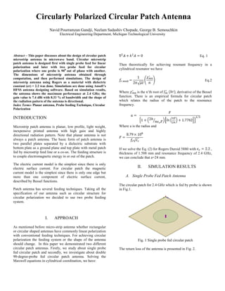
A. Single Probe Fed Patch Antenna
The circular patch for 2.4 GHz which is fed by probe is shown
in Fig.1.
Fig. 1 Single probe fed circular patch
The return loss of the antenna is presented in Fig. 2.
2. 1.00 1.50 2.00 2.50 3.00 3.50 4.00
Freq [GHz]
-12.50
-10.00
-7.50
-5.00
-2.50
0.00
dB(St(WavePort1,WavePort1))
SAS IP, Inc. HFSSDesign1XY Plot 1 ANSOFT
m3
Curve Info
dB(St(WavePort1,WavePort1))
Name X Y
m3 2.4000 -12.2455
Fig. 2 return loss of the antenna, the resonance is occurring in
2.4 GHz
The bandwidth percentage is 4.3% in this antenna and the
resonance is at 2.4 GHz. The polarization in this antenna is
linear. The E field from side and top view are shown in Fig.3
and 4.
Fig.3 Side view of electric field
Fig. 4 Top view of electric field
The axial ratio of this antenna is presented in Fig.5. It can be
deduced from this antenna that the axial ratio is around 17
which shows that the antenna polarization is linear.
89.00 89.25 89.50 89.75 90.00 90.25 90.50 90.75 91.00
Theta [deg]
16.50
17.00
17.50
18.00
18.50
18.75
mag(AxialRatioValue)
HFSSDesign1XY Plot 10 ANSOFT
m1
Curve Info
mag(AxialRatioValue)
Setup1 : LastAdaptive
Name X Y
m1 90.0000 17.6341
Fig.5 The axial ratio of simulated single probe fed which is around 17
B. Double 90˚-Phased Shifted Probe Fed Circular
Patch
For obtaining circular polarization the feeding system should
change. Fig. 6 shows one of the techniques that can be used to
create circular polarization. In this method two probes are
applied to the patch by 90 degree phase difference.
Fig. 6 Double Fed Patch Antenna
For creating 90 degree phase shift we used quarter wavelength
phase shifter at 2.4 GHz. Fig. 7 shows our simulated antennas.
Fig. 7 Double fed simulated antenna
The return loss for this antenna is depicted in Fig. 8. It is
shown that the resonance is at 2.4 GHz. The bandwidth of this
antenna is 8.3% which is two times greater than the previous
one which is fed by single probe.
1.50 1.75 2.00 2.25 2.50 2.75 3.00
Freq [GHz]
-14.00
-12.00
-10.00
-8.00
-6.00
-4.00
-2.00
0.00
dB(St(Cylinder1_T1,Cylinder1_T1))
HFSSDesign1XY Plot 16 ANSOFT
m1
Curve Info
dB(St(Cylinder1_T1,Cylinder1_T1))
Setup1 : Sweep1
Name X Y
m1 2.4000 -13.4822
Fig. 8 Return loss for double fed circular patch
The radiation pattern in E-plane and H-plane for the antenna is
presented in Fig.9.
3. Fig. 9 radiation pattern for double probe fed
The Axial ratio for this antenna is about 1.6 which is showing
that this antenna is nearly circularly polarized. Fig 10 shows
the axial ratio for this antenna.
89.00 89.25 89.50 89.75 90.00 90.25 90.50 90.75 91.00
Theta [deg]
0.50
1.00
1.50
2.00
2.50
2.75
mag(AxialRatioValue)
HFSSDesign1XY Plot 6 ANSOFT
m1
Curve Info
mag(AxialRatioValue)
Name X Y
m1 90.0000 1.6274
Fig 10 Axial Ratio for double fed Patch antenna
C. Gain Comparison
The antenna with two probe has the higher gain than the
patch only with one probe. Fig. 11 shows that the antenna
with two probe has 7.4 dB Gain and the antenna with one
probe has 4.3 dB.
Fig. 11 Gain comparison between two different techniques
III. Effect of Patch Radius and Substrate
Thickness on the Resonance Frequency
According to Eq. 2 resonance frequency is inversely related to
patch radius. Fig. 12 shows the dependency of resonance
frequency to the patch radius. It is shown that as the
dimension of the patch increases the frequency of resonance
will decrease and the return loss value will decrease either.
Fig. 12 Dependence of resonance frequency to the patch
dimension.
The effect of substrate thickness is also investigated. Fig. 13
shows the relation between resonance frequency and the
thickness of the substrate. It can be seen that resonance
frequency is weakly increase by decrease of substrate
thickness.
Fig. 13 Dependence of resonance frequency to the substrate
thickness.
IV. CONCLUSION
In this paper we have designed two circular patch antennas.
Our antenna is fed by probe from the bottom. Our designed
antennas have both linear and circular polarization. Our
circular antenna has the gain of 4.28 dBi for linear and 7.4 dBi
for circular polarization.
References
[1]. Balanis, “Antenna Theory: Analysis and Design”, Wiley
Interscience, 3rd Ed. 2005
[2]. Y. Rudy, A. Baskoro and A.D. Erfan, “Design of Circular Patch
Microstrip Antenna for 2.4 GHz RFID Applications ”, Springer, Vol.
235, pp 21-28, 2013
[3]. K.C. Gupta, “Microstrip Antenna Design”, Artech House, 1988
![1.00 1.50 2.00 2.50 3.00 3.50 4.00
Freq [GHz]
-12.50
-10.00
-7.50
-5.00
-2.50
0.00
dB(St(WavePort1,WavePort1))
SAS IP, Inc. HFSSDesign1XY Plot 1 ANSOFT
m3
Curve Info
dB(St(WavePort1,WavePort1))
Name X Y
m3 2.4000 -12.2455
Fig. 2 return loss of the antenna, the resonance is occurring in
2.4 GHz
The bandwidth percentage is 4.3% in this antenna and the
resonance is at 2.4 GHz. The polarization in this antenna is
linear. The E field from side and top view are shown in Fig.3
and 4.
Fig.3 Side view of electric field
Fig. 4 Top view of electric field
The axial ratio of this antenna is presented in Fig.5. It can be
deduced from this antenna that the axial ratio is around 17
which shows that the antenna polarization is linear.
89.00 89.25 89.50 89.75 90.00 90.25 90.50 90.75 91.00
Theta [deg]
16.50
17.00
17.50
18.00
18.50
18.75
mag(AxialRatioValue)
HFSSDesign1XY Plot 10 ANSOFT
m1
Curve Info
mag(AxialRatioValue)
Setup1 : LastAdaptive
Name X Y
m1 90.0000 17.6341
Fig.5 The axial ratio of simulated single probe fed which is around 17
B. Double 90˚-Phased Shifted Probe Fed Circular
Patch
For obtaining circular polarization the feeding system should
change. Fig. 6 shows one of the techniques that can be used to
create circular polarization. In this method two probes are
applied to the patch by 90 degree phase difference.
Fig. 6 Double Fed Patch Antenna
For creating 90 degree phase shift we used quarter wavelength
phase shifter at 2.4 GHz. Fig. 7 shows our simulated antennas.
Fig. 7 Double fed simulated antenna
The return loss for this antenna is depicted in Fig. 8. It is
shown that the resonance is at 2.4 GHz. The bandwidth of this
antenna is 8.3% which is two times greater than the previous
one which is fed by single probe.
1.50 1.75 2.00 2.25 2.50 2.75 3.00
Freq [GHz]
-14.00
-12.00
-10.00
-8.00
-6.00
-4.00
-2.00
0.00
dB(St(Cylinder1_T1,Cylinder1_T1))
HFSSDesign1XY Plot 16 ANSOFT
m1
Curve Info
dB(St(Cylinder1_T1,Cylinder1_T1))
Setup1 : Sweep1
Name X Y
m1 2.4000 -13.4822
Fig. 8 Return loss for double fed circular patch
The radiation pattern in E-plane and H-plane for the antenna is
presented in Fig.9.](data:image/gif;base64,R0lGODlhAQABAIAAAAAAAP///yH5BAEAAAAALAAAAAABAAEAAAIBRAA7)