
Empfohlen
Empfohlen
Weitere ähnliche Inhalte
Was ist angesagt?
Was ist angesagt? (20)
Andere mochten auch
Andere mochten auch (20)
Ähnlich wie SPPVersion9Final
Ähnlich wie SPPVersion9Final (20)
SPPVersion9Final
- 1. 1
- 2. By: Dave Jacob Matthias Miller Randy Swartz
- 3. Objectives Introduction Hydrogen Today Current Production Techniques What is Photoelectrolysis? Benefits Problems Experimental Methods Results Conclusion 3
- 4. Develop effective photosensitive metal oxides to increase the efficiency of hydrogen production through photoelectrolysis Reproduce results and refine procedures developed by other research groups Lay groundwork for future research in this field at JMU 4
- 5. Hydrogen: Quick Facts Current State Conventional Methods Steam Methane Reforming ○ Problems Electrolysis Photoelectrolysis What is it? Benefits 5
- 6. Hydrogen may have a future as an ideal energy carrier Hydrogen has the highest energy density per unit weight Significant infrastructure barriers are currently keeping hydrogen technology from mainstream use 6
- 7. There are two main ways that hydrogen is made today Steam Reformed Methane (SRM) Electrolysis 7
- 8. STEP 1: Methane reacts with the steam to produce a synthesis gas made up of hydrogen and carbon monoxide STEP 2: the carbon monoxide reacts with the steam over a catalyst to form hydrogen and carbon dioxide 8
- 9. Carbon dioxide and small amounts of carbon monoxide and hydrogen sulfide are byproducts of the process Current technologies that use hydrogen cannot handle the impurities in the resulting products Further purification (both in feedstock and product) is required – increasing costs 2224 42 HCOOHCH 9
- 10. Uses direct current to separate hydrogen atoms from the oxygen atoms in water The oxygen-containing anion migrates to the anode (+) and the hydrogen cation migrates to the cathode (-) Hydrogen gas is generated at the cathode and separated from the oxygen gas generated at the anode Typical electrolyte used is Potassium Hydroxide 10
- 11. Anodes and cathodes alternatively spaced in a tank filled with 20- 30% of an electrolyte The electrodes are connected in parallel Advantages: easy to repair and easy to manufacture 11
- 12. In the U.S. 95% of all hydrogen produced comes from Methane Therefore, CO2 is still being released to the atmosphere Hydrogen produced from standard electrolysis utilizes electricity from the grid, which is predominately derived from fossil fuels Fossil fuels provided 71% of electricity across all sectors in 2008 Of the electricity from fossil fuels, 68% was from coal Photoelectrolysis has the potential to offer entirely emission-free energy 12
- 13. Same idea as normal electrolysis, but supplied current is directly created by absorption of sunlight by photosensitive semiconductors Types of Photoelectrolysis: Photovoltaic Photovoltaic/Semiconductor Liquid Junction Semiconductor-Liquid Junction 13
- 14. Figure shows electrolysis done with electricity directly from a PV unit. Source: Currao, 2007 14
- 15. Figure shows electrolysis using electricity from PV unit and a photosensitive anode. Source: Currao, 2007
- 16. Figure shows electrolysis done with electricity directly from photosensitive anodes. Source: Currao, 2007
- 17. Low efficiency (typically <1%, highest around 12%) Requires a bias voltage to produce viable amounts of hydrogen Practicality High cost Still in experimental phase Scalability issues 17
- 18. 1. Materials Preparation 2. Anodic Oxidation O-Ring Fixture 3. SEM Pictures 4. Alpha-Step 5. Annealing 6. Electrode Preparation 7. Photoelectrolysis Testing 18
- 19. Cut 0.7 mm thick titanium sheet into 20 mm by 20 mm pieces Remove burrs Hand-grind with wet-dry silicon carbide abrasive paper, (240-grit to 1000-grit), washing the sample in between grit changes Polished in Leco VP-160 grinder/polisher with diamond paste; cleaned, then polished again with colloidal silica, then final cleaned 19
- 20. To make our electrodes, metal was anodized in an electrolyte with an applied voltage An electrolyte is needed instead of pure water to produce nanostructured oxides at reasonable rates Anodization of a sample in our laboratory 20
- 21. 21
- 22. The anodization reaction: describes the creation of the titanium oxide film eHTiOOHTi 22 22 22
- 23. The anodization reaction: describes the creation of the tungsten trioxide eHWOOHW 63262 23 23
- 24. Tungsten used was too thin for anodization in some electrolytes; electrolyte would dissolve holes through the tungsten from each side A fixture was designed and fabricated that exposes only one side of the tungsten foil to the electrolyte 24
- 25. 25
- 26. Summary of Anodization Statistics Type Sample Time (mins) Voltage (V) Electrolyte Titanium Oxide 021 90 55 NH4F 022* 100 90 023 90024 025 Tungsten Oxide 013 - 85 1M H2SO4 015 60 50 1M H2SO4 (0.5% NaF) 017 210 20 1.5M HNO3 007 65 60 NaF 26 * Sample “020” was stripped and re-anodized and labeled sample “022”
- 27. Once samples had been created, they were examined on a scanning electron microscope to see what nanostructures were present Three possible nanostructures: Nanopores Nanotubes Nanoplatelets 27
- 28. First structure we were able to develop through anodization before we refined our process Both metal oxides tested (as well as several others) are capable of forming nanoporous structures 28
- 29. 29
- 30. 30
- 31. WO3-007 a 31
- 32. Titanium dioxide has the potential to organize in structures called nanotubes The openings in these hexagonally- arranged tubes are wider at the top and narrow as depth increases These tubes are desirable features because they increase the surface area of the photoactive material 32
- 33. 33
- 34. 34
- 35. 35
- 36. 36
- 37. One of the possible structures that can form when anodizing tungsten Called platelets because the film consists of randomly arranged flat rectangular shapes Desirable because they reflect and trap light increasing the efficiency of the semi- conductor film 37
- 38. 38
- 39. 39
- 41. Surface profiler used to measure film thickness and surface roughness Highly-sensitive stylus moves across testing surface 41
- 42. TiO2 samples had nanostructure film thicknesses ranging from 9.5 to 12 μm The tungsten foil was not completely flat Prevented the stylus of the Alpha Step from giving an accurate reading Stylus actually gouges the WO3 film WO3 samples had nanostructure film thicknesses of approximately 0.9 μm 42
- 43. Nanostructures must be crystalline to function as a photosensitive electrode Heating of samples allows atoms to rearrange in the appropriate crystalline lattice structure Type Sample # Annealing Time (hrs) Temperature (°C) Gas Titanium Oxide 021 3 500 O2 022* STRIPPED, REGROWN 3 500 O2 023 3% H2/N2 024 3% H2/N2 025 O2 Tungsten Oxide 013 3 400 O2 015 017 007 43
- 44. Mellen 3-Zone Tube Furnace 44
- 45. A wire must be attached to allow a current to run through sample A small area is scraped down to bare metal, and a wire attached with electrically conductive silver epoxy Baked in Isotemp Vacuum Oven for 1 hour from 78°F-80°F To define the test area, the entire sample was covered with electrically-insulating epoxy (except for test area) 45
- 46. Isotemp Vacuum Oven 46
- 47. An example of a sample that is ready for testing The surface area meant for testing can be seen Epoxy covers the rest of the sample 47
- 48. Testing of each electrode ran for 120 seconds Light from Mercury Vapor lamp was alternately blocked and unblocked for 20 second intervals Voltage and current measured to see if electrode was light sensitive 48
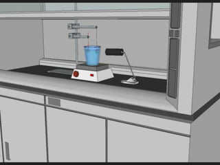
- 49. A sample being tested with incoming light source in our laboratory 49
- 50. 50
- 52. -1 -0.9 -0.8 -0.7 -0.6 -0.5 -0.4 -0.3 -0.2 -0.1 0 0 20 40 60 80 100 120 Voltage(V) Time (sec) TiO2-025 Photovoltage 52
- 53. -0.05 0 0.05 0.1 0.15 0.2 0.25 0.3 0.35 0.4 0.45 0.5 0 20 40 60 80 100 120 Current(mA) Time (sec) TiO2-025 Photocurrent Zero Bias 0 0.1 0.2 0.3 0.4 0.5 0.6 0.7 0.8 0 20 40 60 80 100 120 Current(mA) Time (sec) TiO2-025 Photocurrent 1V Bias 53
- 54. -0.59 -0.589 -0.588 -0.587 -0.586 -0.585 -0.584 0 20 40 60 80 100 120 Voltage(V) Time (sec) WO3-007 Photovoltage An SEM image of sample WO3-007 54 * Note: each time the sample was blocked, the plot moves closer to zero
- 55. -0.02 0 0.02 0.04 0.06 0.08 0.1 0 20 40 60 80 100 120 Current(mA) Time (sec) WO3-007 Photocurrent Zero Bias -0.2 0 0.2 0.4 0.6 0.8 1 0 20 40 60 80 100 120 Current(mA) Time (sec) WO3-007 Photocurrent 1V Bias 55
- 56. We succeeded for the first time at JMU in producing a variety of nanostructures in TiO2 and WO3 (nanopores, nanotubes, nanoplatelets) Hydrogen and oxygen were produced The TiO2 nanotubes produced a small current without any voltage applied For TiO2, nanotubes proved to be the best of the three nanostructures The WO3 samples produced similar results 56
- 57. The amount of hydrogen produced can be predicted from the measured current flow If a current of 1 mA flows for 1 hour, we expect to generate 0.42 mL of hydrogen 57
- 58. Design test fixture/rig that would allow capture of generated hydrogen and oxygen Quantify amounts of hydrogen and oxygen produced Develop materials that will produce larger photocurrents with smaller or no applied voltage Develop P-type materials for photocathodes 58
- 59. Propose practical photoanode architectures Efficiency gains will hopefully allow for commercialization 59 Proposed Integrated PV cell and Photoanode setup
- 60. We would like to thank: Our Advisor, Dr. David J. Lawrence JMU Machinist Mark Starnes Drs. Gopal Mor & Craig Grimes from Penn State CISAT Mini-Grant Family Friends Without whom this project would not have been possible 60
- 62. Mor, G., Varghese, O., Paulose, M., Mukherjee, N., & Grimes, C. (2003). Fabrication of tapered, conical-shaped titania nanotubes. Journal of Materials Research, 18(11), 2588-2593. doi: 10.1557/JMR.2003.0362. Currao, A. (2007). Photoelectrochemical Water Splitting. CHIMIA International Journal for Chemistry, 61(12), 815-819. doi: 10.2533/chimia.2007.815. 62
- 63. Type Sample # Peak Current Density (mA/cm2) No Bias 0.5V 1V 1.5V 2V 2.5V TiO2 021 0.42 0.50 0.54 0.62 0.69 0.82 022* 0.79 0.93 0.97 1.05 1.10 1.13 023 0.10 - - - - - 024 0.08 0.11 0.14 0.23 0.37 0.53 025 0.72 0.98 1.14 1.44 2.8 4 WO3 013 0.01 0.72 0.59 2.12 6.01 6.14 015 0.04 1.15 0.78 2.00 4.71 4.61 017 0.05 0.69 1.83 2.85 5.59 5.69 007 0.09 1.36 3.26 4.86 6.57 7.43 63
- 64. 64
- 65. 65
- 66. 66
- 67. 67
- 68. 68
- 69. 69
- 70. 70
- 71. 71
- 72. 72
- 73. Electrolysis: Bipolar Design Alternating layers of electrodes and separation diaphragms clamped together The cells are connected in a series circuit and result in higher stack voltages The bipolar design has higher current densities and produces higher-pressure gas compared to that of the unipolar, however if it needs repair, the entire stack must be replaced 73
- 74. 74
Hinweis der Redaktion
- Even though Electrolysis is well known for producing hydrogen, the United States produces 95% of its hydrogen from a technique known as Steam Methane Reforming. Using this technique, steam at an extremely high temperature (usually around 700 degrees Celsius or 1000 degrees Celsius) is used to produce hydrogen from a methane source (like natural gas). The SMR consists of two steps. In the first step the methane reacts with the high-temperature steam to produce a synthesis gas primarily made up of hydrogen and carbon monoxide. The second step is also known as the water gas shift reaction. Here the carbon monoxide reacts with the steam over a catalyst to form hydrogen and carbon dioxide. This step is broken down to stages; one stage is a high temperature shift around 350 degrees Celsius, and the other a low temperature shift around 200 degrees Celsius Because hydrogen production with SMR has small amounts of carbon monoxide, carbon dioxide and hydrogen sulfide as byproducts of the process, some processes require further purification. The two major purification steps to obtain a pure hydrogen product are feedstock purification and product purification. Feedstock purification removes sulfur and chloride in order to sustain the downstream steam reforming and other catalysts. Product purification uses a light absorption system to remove carbon dioxide, while the product gas also passes through a methanation step to remove traces of carbon oxides. It is important to eliminate the impurities from the hydrogen product because they are thought to cause problems in the fuel cell designs that we have today. That being said, most standards for hydrogen needs require further purification because the systems that are in place to harness the energy can’t handle the impurities. This disadvantage to SMR brings up a good reason to search for alternative hydrogen production techniques.
- Electrolysis uses direct current to separate hydrogen atoms from the oxygen atoms in water. (Kroposki 5) Positive and negative electrodes are used to pass an electric current through water (or an electrolyte). In an electrolysis setup, the anode is positively charged while the cathode is negatively charged. Electrolysis of pure water is extremely slow, so to quicken the reactions, an electrolyte that is a strong acid (such as sulfuric acid) or a strong base (such as potassium hydroxide), is added to the water. When the current is passed through the water the molecules are split, causing the oxygen molecule to rush to the anode and the hydrogen molecule to rush the cathode. The hydrogen molecules are isolated from the oxygen molecules and the hydrogen gas is extracted for fuel. There are different techniques to electrolysis that deal with where to put the electrodes in the water, as well as how many electrodes are needed to gain the maximum amount of hydrogen. Electrolyzers can be configured as unipolar (tank) or bipolar (filter press) as shown in Figures 1 and 2, respectively. The unipolar design has anodes, and cathodes alternatively spaced in a tank filled with 20-30% of an electrolyte. The electrodes are connected in a parallel series. (Ivy 4) The advantage to this design is that it is easy to repair and easy to manufacture. The bipolar design has alternating layers of electrodes and separation diaphragms clamped together. The cells are connected in a series circuit and result in higher stack voltages. The bipolar design has higher current densities and produces higher-pressure gas compared to that of the unipolar, however if it needs repair, the entire stack must be replaced. (Kroposki 6) Figure 3: PEM Design Another electrolysis technology is known as a solid polymer electrolyte membrane (PEM). The electrolyte in this unit is a “solid ion conducting membrane,” compared to the liquid solution such as alkaline electrolyzers. The membrane allows hydrogen ions (H+) to go from the anode side to the cathode side, where the hydrogen forms. The membrane also plays a part in separating hydrogen and oxygen gasses. In order to perform Electrolysis effectively there are many other factors to consider when implementing a process design. A system depends first on what kind of electrolysis technology it is using. If a system is using the PEM design, it is not going to need a tank for its electrolytic solution because the electrolyte, as stated earlier, is solid. Electrolysis also requires purified water in order to work correctly and efficiently. Some systems require an “external deionizer or reverse osmosis unit” before the water enters the stacks, while some systems have a water purification unit inside their hydrogen generating unit. Systems also need a source of water to run electrolysis continuously which requires a water storage tank. On the other hand there are some processes that take advantage of hydrodynamics to power electrolysis and also take in some water eliminating the need for a storage tank. Overall each system has a hydrogen generation unit that incorporates the electrolysis stack (Unipolar, Bipolar, or PEM), gas purification and dryer, and heat removal unit. Electrolysis has different techniques all that have their advantages and disadvantages, but what makes electrolysis attractive for future hydrogen production is the fact that it can get its electrical power from other renewable energy sources, as previously mentioned.
- Most common electrolyte, KOH
- Semiconductor 1 = N Type Semiconductor 2 = P Type
- two pieces of polypropylene sandwiching the sample between two O-rings another piece of backup metal soldiered to a wire snaked up through the neck of the fixture The two pieces of the fixture were bolted together with chemically inert nuts and bolts made of a polymer called PEEK (polyether ether ketone
- NH4F = Ammonium Fluoride H2SO4 = Sulfuric Acid HNO3 = Nitric Acid NaF = Sodium Fluoride
- Circular tube, “honeycomb” arrangment Human hair is 100 micrometers in diameter, NTs are 100 nm. Thus 1,000 would fit in diameter. Half a million to a million of these would fit on the end of a human hair.
- Vertical platelets
- Horizontal platelets
- Tungsten oxide film was delicate. Surface profiler needle possibly cut through oxide film.
- After the samples were annealed, they needed to be prepared to be placed in the electrolysis experimental setup. To do this, a wire needed to be attached to allow a current to run through it. This was accomplished by scraping away a small area of oxide to expose the bare metal on the front face of the sample, near the edge oriented upwards. The wire was then attached to the sample using two types of expoxy: electrically-conductive silver epoxy. Additionally, the sample was completely covered (both sides, and edges) in electrically-insulating epoxy except for a control area that would be exposed to the electrolyte and the incoming electromagnetic radiation. After the samples were covered in epoxy, they were placed in a Isotemp Vacuum Oven for 1 hour at 78F-80F to cure.
- Immediately after anodization the NT’s are not crystalline