
Empfohlen
Empfohlen
Weitere ähnliche Inhalte
Andere mochten auch
Andere mochten auch (8)
Ähnlich wie HPHR_Quantum_Design_Example_112012
Ähnlich wie HPHR_Quantum_Design_Example_112012 (20)
HPHR_Quantum_Design_Example_112012
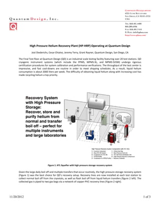
- 1. 11/20/2012 1 of 3 High Pressure Helium Recovery Plant (HP-HRP) Operating at Quantum Design Jost Diederichs, Cesar Chialvo, Jeremy Terry, Grant Rayner, Quantum Design, San Diego, CA The Final Test floor at Quantum Design (QD) is an industrial scale testing facility featuring over 20 test stations. QD cryogenic instrument systems (which include the PPMS, MPMS-XL, and MPMS-SVSM) undergo rigorous certification procedures for system calibration and performance verifications. The throughput of the test center is impressive, and fast cool-downs are routine in order to meet shipping schedules. As a result, liquid helium consumption is about 2000 liters per week. The difficulty of obtaining liquid helium along with increasing cost has made recycling helium a top priority. Figure 1: ATL liquefier with high pressure storage recovery system Given the large daily boil off and multiple transfers that occur routinely, the high pressure storage recovery system (Figure 1) was the best choice for QD's recovery setup. Recovery lines are now installed at each test station to collect normal boil off from the cryostats, as well as flash boil off from liquid helium transfers (figure 2 left). The collected gas is piped to two gas bags via a network of copper-PVC recovery lines (Figure 2 right).
- 2. 11/20/2012 2 of 3 Figure 2 (left) Recovery line at individual test station (right) Gas bags A fully automatic controller continuously monitors the pressure in the gas bags, and engages the HP compressor whenever the pressure in the gas bag exceeds a preset threshold. In this way, helium gas is emptied out of the gas bag and compressed into gas bottles for short term storage (Figure 3, left and right). The controller reports the status of bag pressure and HP compressor (Figure 4 left), and retains a log record for bag pressure and compressor duty cycles for a period of five years (figure 4 right). The current HP compressor is able to process a 5 liquid liter equivalent of gas per hour, but it will be soon expanded to a 20 L per hour capacity. Figure 3 (left) High pressure compressor (right) "Dirty" helium storage in cylinders
- 3. 11/20/2012 3 of 3 Figure 4 (left) Gas bag and compressor controller (right) GUI of the controller showing log graph The "dirty" gas (0.5% air) from the gas cylinders is then sent through the Advanced Technology Purifier (ATP30) for purification (Figure 5 left). The ATP can handle a helium flow of 30 L/min to output high purity gas (99.9995% purity) to a fleet of ATL160 liquefiers with liquefaction rates of over 20 liters per day per system (Figure 5 center). The collected liquid helium is transferred back into systems on the test floor using standard transfer lines (Figure 5 right). The mobile design of the ATL160 makes these transfers routine and easy. Figure 5. (left) ATP30 (center) ATL160 fleet (right) Transfer from ATL to PPMS Dewar In order to meet the 2000 liter per week usage on Quantum Design's Final Test Floor, the QD liquefier fleet will soon expand to include 10 ATL160s and 5 ATP30s. This is a great example showcasing ATL160 HP-HRP technology, which can be scaled up to serve any sizable Industrial testing center, or large departments on university campuses.