Back-analysis of the collapse of a metal truss structure

This paper is organized in two parts. The first one describes a case history of few collapses of metal truss structures designed to be used as entertainment structures for which the structural safety gains therefore much more importance due to the people that can be involved in the collapse. In the second part, a specific case of the collapse of an entertainment structure made by aluminum is taken under study. A back analysis of the collapse of this metal truss structure is developed and produces a flowchart that points out the possible causes that led the structure to the collapse. By means of non linear analyses by Finite Element Model (FEM) the failure sequence of this particular structure is shown and forensic investigation concerning the whole phase of the construction phase is performed, starting from the design one, through the assembling and ending with the rigging phase.

Empfohlen
Empfohlen
Weitere ähnliche Inhalte
Was ist angesagt?
Was ist angesagt? (20)
Andere mochten auch
Andere mochten auch (20)
Ähnlich wie Back-analysis of the collapse of a metal truss structure
Ähnlich wie Back-analysis of the collapse of a metal truss structure (20)
Mehr von Franco Bontempi
Mehr von Franco Bontempi (20)
Kürzlich hochgeladen
Kürzlich hochgeladen (20)
Back-analysis of the collapse of a metal truss structure
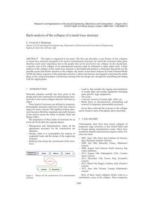
- 1. Research and Applications in Structural Engineering, Mechanics and Computation – Zingoni (Ed.) © 2013 Taylor & Francis Group, London, ISBN 978-1-138-00061-2 Back-analysis of the collapse of a metal truss structure C. Crosti & F. Bontempi School of Civil and Industrial Engineering, Department of Structural and Geotechnical Engineering, Sapienza University of Rome, Italy ABSTRACT: This paper is organized in two parts. The first one describes a case history of few collapses of metal truss structures designed to be used as entertainment structures for which the structural safety gains therefore much more importance due to the people that can be involved in the collapse. In the second part, a specific case of the collapse of an entertainment structure made by aluminum is taken under study. A back analysis of the collapse of this metal truss structure is developed and produces a flowchart that points out the possible causes that led the structure to the collapse. By means of non linear analyses by Finite Element Model (FEM) the failure sequence of this particular structure is shown and forensic investigation concerning the whole phase of the construction phase is performed, starting from the design one, through the assembling and ending with the rigging phase. 1 INTRODUCTION Particular attention recently has been given to the design and to the construction of entertainment struc- tures due to the recent collapses that have had them as object. Those kinds of structures are defined as temporary demountable structures and most of the time used as stages for music concerts. The stability of these struc- tures becomes therefore important especially because of the need to assure the safety of people (Andi and Minato 2003). The preparation of these kinds of structures for an event can be divided into separate phases: – Management and Administration, where all the agreements necessary for the construction are obtained; – Design, where it is contemplates the analysis of suspended loads and the design of the supporting structure; – Build-up, that means the construction of the struc- tures; Figure 1. Phases for the construction of an entertainment structure. – Load in, that includes the rigging and installation of sound, light, and similar equipment (including artist specific stage equipment); – The event; – Load out, removal of sound, light, video, etc; – Break down or deconstruction, dismantling and removal of temporary demountable structures. Errors that could lead the structure to the collapse can be found in each of the phases above described. 2 CASE HISTORY Unfortunately, there have been recent collapses of temporary stage structures in the United States and in Europe during entertainment events. These have resulted in fatalities and numerous injuries, below few cases are listed: – 2007, June 15th, Parco San Giuliano di Venezia, Italy, Heineken Jammin’ Festival; – 2009, July 20th, Marseille, France, Madonna’s concert; – 2009, August 1nd, Camrose North America, Big valley Jamboree; – 2011, August 14th, Indianapolis, USA, Country music concert; – 2011, December 12th, Trieste, Italy, Jovanotti’s concert; – 2012, March 5th, Reggio Calabria, Italy, Pausini’s concert; – 2012, June 16th, Toronto, Canada, Radiohead’s concert. Most of these listed collapses define wind as a contributory cause of the collapse. These temporary 2401
- 2. Figure 2. Collapses of entertainment structures. Figure 3. Most frequent errors in the phases before the event. structures are exposed to vertical imposed loadings from attached lighting and sound equipment and also, when outdoor, to lateral loadings resulting from wind. The risk is that when the structure is subjected to combined vertical equipment loads, to the horizon- tal wind loads and to the eccentric vertical loads, the resulting forces can cause catastrophic failures which may result in collapse if the structure is not compe- tently designed, constructed, and managed in use. Learning from the past it is possible to point out some frequent errors which could lead structures to collapse, (Sebastiani, 2012), (Sgambi, 2012). Where error is defined as “something that has been done, which was: not intended by the author; not desired by a set of rules or an external observer; or that lead the task or system outside its acceptable limits” (Senders, 1991). Focusing on the phases previous the event Figure 1 shows some of the most frequent errors that could be seen as principal factors for structural failure. Most of them can be classified as human errors due to the poor knowledge, to the carelessness and negligence (Love, 2008). Inadequate site investigation, inappropriate ground condition, inadequate structural design, failure to adopt standard procedures or failure in realizing what prescribed in the design and in the regulations, are all factors that can contribute to a catastrophic event, (Suraji, 2001). Figure 4. Structure under study. 3 CASE STUDY: NUMERICAL MODELING The structure under study is an entertainment structure that collapsed skidding on the stage left before the event had started. The structure was made by precast aluminum ele- ments which composed a space roof, six vertical towers and a small truss necessary for suspending scenographic lighting, speakers and videos, Arangio (2011). The structure was built with EN AW-6082 T6, with modulus of elasticity (E) equal to 7×10¹⁰ Pa, density (ρ) of 2700 Kg/m3 , elastic limit for the strength (σy) of 2.5×10⁸ Pa and ultimate strength (σu) of 2.9 × 10⁸ Pa, (Mazzolani, 2012), EN1993 1-1 (2005). Using Strand7/Straus7, a Finite Element Model is defined as shown in Figure 4, with 2148 nodes and 5275 beams. In order to take account of the weight of the con- nection between the elements, made in cast iron, an additional uniform pressure of 115 Pa is considered on the roof. The suspending loads present at the moment of the collapse are applied as shown in Figure 4. In this way, the weight of the whole structure is about 28.5 tons. 4 INVESTIGATION ON TECHINAL CAUSES OF THE COLLAPSE Three are the main aspects investigated to individu- ate the cause of the collapse of the structure: failure to adopt standard procedures, inadequate structural design, improper construction procedure, see Figure 2. 4.1 Failure to adopt standard procedures A failure to adopt standard procedures could have been for example to design the structure not including in the global analyses the nonlinearities, in particular the 2402
- 3. Figure 5. Deformed shape of the first mode of buckling. geometric ones. The EN 1993-1-1: 2005 at point 5.2.1 says that: “The effects of the deformed geometry (second- order effects) should be considered if they increase the action effects significantly or modify significantly the structural behavior” This consideration can be neglected only when: Where αcr is the factor by which the design loading have to be increased to cause elastic instability in a globalmodel,FED isthedesignloadingonthestructure and Fcr is the elastic critical buckling load for global instability mode based on initial elastic stiffnesses. Running linear buckling analysis on this specific structure, the buckling factor αcr is 6.44, Figure 5. Since it is smaller than 10 the second order effects have to be taken into account in the global analyses. In the next paragraph it will shown how much difference gives to neglect them. 4.2 Inadequate structural design Another important aspect investigated is that the struc- ture is designed to be indoor; therefore the structural elements were designed to carry vertical loads but may not have been designed for lateral loads. That could be an important consideration in the design phase, in fact, following what prescribed in the UNI ENV 1999- 1-1:2007, in order to run global analyses, it is neces- sary to take account of horizontal forces due to the imperfectionsoftheelementscomposingthestructure. At point C4.1 of the UNI ENV 1999-1-1:2007 it is explained how to take into account of the imper- fection in the global analyses. Therefore, rather than applying to each element a lateral imperfection, three horizontal forces, in correspondence of lower elements composing the space roof have been applied to the structure. 4.3 Improper construction procedure The latest consideration will be conducted on the possibility of improper construction procedures. The attention is focused on the realization of restraints between the paving and the columns in order Table 1. Horizontal forces applied to simulate the imperfections. φ 0.005 kc 1.225 > 1 nc 1.000 ks 1.225 > 1 ns 1.000 φ0 0.005 Ndead load 2.25E+05 N φN 1.13E+03 N Figure 6. Unilateral restraint on the bottom of each column. Figure 7. Cases with hinged restraints, on the left with outriggers and on the right with no outriggers. to assess how and how much an error in defining or in realizing them could compromise the whole structural behavior, (Crosti, 2012). Three different models are considered in order of taking account of some aspects: – the possibility that, due to horizontal displacements caused by the structural imperfections, the outrig- gers could lose the contact with the paving. To simulate this case, eight point-contact elements are set to simulate the contact between those elements and the paving, Figure 6.The point contact element in the Finite Element Code Strand7/Straus7 is used to model a gap between two surfaces or edges, stiff- ness is provided in compression but zero stiffness is given in tension; – it could happen that during the phase of the con- struction for example, what it is designed to be a rigid connection, could be realized for a while as able to rotate. To simulate this aspect hinged restraints are considered on the bottom of each column, Figure 7; and 2403
- 4. Table 2. Definition of the studied models. Model GNL MNL Imperfection Restraint Outriggers ULf 0 X Fixed X 6.942 1 X X Fixed X 4.000 2 X X X Fixed X 3.946 3 X X X Unilateral X 4.019 4 X X X Hinged X 1.122 5 X X X Hinged 0.853 Figure8. LoadFactor-HorizontalDisplacementofthenode. – the case where hinged restraints are on the bottom of each column but no outriggers are set, Figure 7. 5 NUMERICAL RESULTS Five different models were run in order to assess the influence that the above mentioned errors give to the global response of the structure under study. Table 2 summarizes the different models consid- ered, where MLN means Nonlinear Material, GNL stays for Nonlinear Geometry, Imperfection means that horizontal forces simulating the structural imper- fection defined by Eurocodes are applied, Unilateral means that the bottom column is modeled with uni- lateral restraint, see Figure 6, Hinged considers as restraint the ones in Figure 7 and U.L.F. stays for Ultimate Load Factor. Looking at Figure 8 it is possible to recognize that Model 1 has the classical bifurcation trend, while Model 2, thanks to the introduced imperfections, shows an asymptotic one. Reaching the peak load at both ends of the columns, the elements are in an inter- mediate condition, being neither elastic nor having a fully developed plastic hinge mechanism, therefore laborious step-by-step elastic-plastic analyses were necessary to obtain the failure load (ULF) of 3.95. Moreover, interesting is to point out that there is no difference in terms of Ultimate Load Factor as well as of horizontal displacement trend between Model 2 and Model 3. Modeling the contact between the outriggers and the paving does not seem to be a relevant issue in terms of global response of the structure. In fact, Figure 9. Comparison of the Bending Moment trend for element 5211 of the outrigger and element 3001 of the column. looking at Figure 10, it is possible to assess that as soon as the horizontal loads are applied to simulate the structural imperfections, the external points of the outriggers lose the contact with the paving not giving any contribution to the stability of the structure. Model 1, 2 and 3 have more or less the same Ulti- mate Load Factor at that peak load they reach the same cause of collapse: elastic-plastic failure of the out- riggers and of the column elements where the roof is connected, this allows the structure to rotate much more and to buckle. Figure 9 shows the reaching of the elastic-plastic failure for the two elements mainly stressed with the increasing of the Load Factor. Figure 10 shows instead a comparison in terms of deformed shape and of maximum vertical displace- ments reached in the outriggers behind column C2 at the moment of the collapse. 2404
- 5. Figure 10. Deformed shape (20%) of the outrigger elements of column C2. Figure 11. Bending moment 1 trend of element 3001 (column C2). A different case is the one of Model 4 that, hav- ing different restraints on the bottom of the columns, reaches an Ultimate Load Factor of 1.122 which means the structural collapse is due just to the nominal loads applied. In this particular configuration once the columns reach the yielding stress the structure loses its stability and the analyses cannot find the solution. The difference shown in Figure 8 between Model 4 and Model 5 is given by the presence of the outrig- gers. Their presence does not give much contribution in terms of structural stability: in fact the Ultimate Load Factor for Model 5 is 23% smaller than the one ofModel4;howeverlookingattheinitialdisplacement their presence decreases them of about 50%. From Figure 11 it is possible to evaluate that for Model 4 and 5, due to the different restraints, as soon as the element reaches the yielding load, the analyses stop, while Model 3 shows a better redistribution of the stresses when they reach the failure load. This large difference in terms of ultimate load shown going from Model 0 to Model 5 shows the Figure12. DeformedshapeofcolumnC2atthecorrespond- ing Ultimate Load Factor. sensitivity of the structure to the modeling of the restraints which involve the columns. 6 CONCLUSION Following the whole construction process of enter- tainment structures, some of the most frequent errors that can be present in it, have been taken under consideration and applied to a specific metal structure. By means of Finite Element Analyses it has been possible to point out that: – Linear analysis can be used just for evaluation of structure critical buckling load, but then, espe- cially for these kinds of structures, proper nonlinear analyses should have been run. – Not accounting of the initial imperfection, leads the results to be different from the real structural behav- ior that they have especially when the restraints are subjected to improper construction procedures. 2405
- 6. – The importance of taking into account, even in the design phase, of what can happen during the built up phase. Particular importance has to be done to the restraints on the bottom of the columns, which represent the key elements for this structure. Dur- ing the phase of construction for example, what it is designed to be a rigid connection (Model 1 ad 2), could be realized for a while as able to rotate (Model 4 and 5). That shows the need of con- sidering the design in all the cases which could make a modification in the static scheme of the structure. Introducing bracing member for exam- ple, the designers could defend the structure from such possible changes in the structure and avoid failure, (Arangio, 2012). This solution could be especially effective in cases where the structures are not designed for horizontal forces that are the indoor ones. A further development could be to take into account of the stiffness of the paving which can be an issue that compromises the structural stability. ACKNOWLEDGEMENTS The authors would like to acknowledge our research team, www.francobontempi.org, the research spin-off StroNGER S.r.l. for the support and Eng. Piergiorgio Perin for providing the use of the Finite Element Code Strand7/Straus7. REFERENCES Andi & Minato, T., (2003). “Representing causal mech- anism of defective designs: a system approach con- sidering human errors.” Construction Management and Economics, 23, 297–305. Arangio,S.,(2012).“Reliabilitybasedapproachforstructural design and assessment: performance criteria and indica- tors in current European codes and guidelines.” Inter- national Journal of Lifecycle Performance Engineering, 1(1), 64–91. Arangio S., Bontempi F., and Ciampoli M. (2011). “Structural integrity monitoring for dependability.” Struct. Infras- truct. E., 7(1), 75–86. Arangio S., Crosti C., Zampetti M., (2011). “Design of aluminum structures for the entertainment industry and analysis of the behavior in fire conditions.” Proc. of the 7th Greek National Conference on Metal Structures, Greece, Volos, September 29–October 1 2011. Bontempi, F., Arangio, S., Gkoumas, K., (2008). “Sys- temic approach for the maintenance of complex structural systems.” Struct. Infrastruct. E., 4(2), 77–94. Crosti, C., Duthinh, D. (2012). “Simplified gusset plate model for failure prediction of truss bridges.” Proc. of the 6th IABMAS Conf., Italy, Stresa, 8–12 July. Crosti, C., Duthinh, D., Simiu, E., (2012). “Risk Consistency and Synergy in Multihazard Design.” J Struct Eng-ASCE, 137(8), 844–849. Giuliani, L., (2012). “Structural safety in case of extreme actions.” Int. J. Lifecycle Performance Engineering, 1(1), 22–40. EN1993-1-1 (2005) Design of steel structures – Part 1-1: General rules and rules for buildings. Comité Européen de Normalisation (CEN) Kim,T.,Kim,J.,Park,J.,(2009).“InvestigationofProgressive Collapse-Resisting Capability of Steel Moment Frames Using Push-Down Analysis.” J. Perform. Constr. Facil., 23, 327–335. Horne M.R., Merchant W., “The stability of frames”. Perga- mon Press. (1965). Love, P. (2008). “Forensic Project Management: An Exploratory Examination of the Causal Behavior of Design-Induced Rework.” IEEE T. Eng. Manage., 55(2), 234–247. Mazzolani F.M., (2012). “La progettazione strutturale delle leghe in alluminio”. Officine grafiche. Novoselac, S. (2012). “Linear and nonlinear buckling and post buckling analysis of a bar with the influence of imperfections.” Technical Gazette, 19(3), 695–701. Petrini F., Bontempi F. (2011), “Estimation of fatigue life for long span suspension bridge hangers under wind action and train transit.” Struct Infrastruct E, 7(7–8), 491–507. Sebastiani, P.E., Petrini, F., Franchin, P., Bontempi, F., (2012). “BackAnalysis for Earthquake Damaged Bridges. Part I: a general procedure” Proc. of the 6th IABMAS Conf., Italy, Stresa, 8–12 July. Senders, J.W. (1991). “Human Error: Cause, Prediction, and Reduction.” Lawrence Erlbaum Associates, Inc., Hills- dale, New Jersey. Sgambi, L., Gkoumas, K., and Bontempi, F. (2012). “Genetic Algorithms for the DependabilityAssurance in the Design of a Long-Span Suspension Bridge”. Comput-Aided Civ. Inf., 27(9), 655–675. Suraji, A. (2001). “Development of causal model of con- struction accident causation.” J.Constr. Eng. Manage, 127, 337–344. Strand7/Straus7, Sydney, NSW,Australia (2010) http://www. hsh.info/ UNI ENV 1999-1-1:2007. “Eurocode 9: Design of aluminum structures – Part 1-1: General structural rules.” 2406