Conspectus data warehousing appliances – fad or future
120901 PMS data handling example
1. Practice Note: on the handling records in a bespoke marine service contract
Dated: 24th August 2012
Page: 1 of 6 (plus 5 figure sheets)
File: 120901 handling of field records.docx
AntonioAssociates Ltd geotechnical project engineering
The systematic record handling in a bespoke marine
geotechnical investigation contract
Routine and technical records must be kept in good order for safety, security and to obtain the
maximum value for the client for the work investment. With new equipment, new techniques, or to
accommodate new client demands, bespoke systems must be developed for the new methodologies
and the associated data handling must accommodate the new site, plant or novel operational
procedure.
Part 1 of this note presents broad, generic ideas of data management and Part 2 describes the
project where examples have come from. Part 3 presents a rapid summary. The note describes just
the immediate data handling (essentially the subsea operations and basic drilling) to what was also a
major geotechnical study in its own right, with huge but separate data handling requirements of its
own. However, there are no doubts in the author’s mind that the underpinning drilling data
described here is linked to the specific technical packages and strongly aided final reporting and
technical analysis and as well as contractual matters. The experiences will therefore have influence
and use in relation to other subsea works.
Ideas and a pinch of experience may be helpful for technically experienced managers (but non-
specialist in IT) to set-up these systems and careful planning is necessary. They must be bespoke,
ergonomic, commensurate with time investment, easy to implement, robust, long-lived (through the
entire project) and readily provide for final reporting, or, a systematic review or audit—on technical
and contractual themes. In this document, the ideas may not appear obvious, and to some even
verbose, but by implementing the simple ideas it will stop the reworking of huge volumes of data at
some later stage or when the inevitable glitch arises. They are based upon experience, are practical
and can be most effectively deployed if all teams can ‘buy-in’ to the approach; but can be singularly
installed for one group, if not.
2. Practice Note: on the handling records in a bespoke marine service contract
Dated: 24th August 2012
Page: 2 of 6 (plus 5 figure sheets)
File: 120901 handling of field records.docx
AntonioAssociates Ltd geotechnical project engineering
Part 1: General comments on data handling
Introduction
To keep the ideas presented here general and universally applicable, the explicit geotechnical
analysis works are omitted from the general discussion but, once basic data handling and control
systems are operational, it is self-evident that a well designed system is the best way of
underpinning all the on-going and future technical analysis that may be subsequently applied in
interpretative reporting or design. The efforts applied in the field at data gathering stage pays huge
dividends to the later phases of reporting, analysis, design and of project control and of contract
audit and claims. In the example given later, the client demands were challenging, multiple layered
and complex, and such complexity extended from field to final reporting phases.
Guiding principles: implicit and explicit project requirements
The obvious preferred principles apply here, as with any data handling task. Any and all the data
gathered, is maintained safely and securely in both raw and post-processed states as much as
possible. It is identified, date-stamped and the source is acknowledged before anything else is done.
The package is always saved, as-is, in a secure place (back-up) before any opening or processing is
commenced. This simple task is key and very necessary. Any reliance upon data copies which sit with
delivery e-mails is not recommended.
As will be discussed later even this very first stage requires careful thought and planning if a later
phase of frantic searching for a lost or replacement original is to be avoided. It is important that a
systematic process is followed which makes sensible use of directory hierarchies and file-naming
conventions. These may be bespoke for the project but (hopefully) will also follow company
standards as well. If there are explicit client demands these can be applied after receiving the raw
data set—it is necessary to secure your data before it is transferred to the client. Of course, there will
be many specialists and/or subcontracts delivering data into a central reporting/analysis system e.g.
surveyors, specialist operators who will likely have their own prescribed systems of security and
back-up. Yet, whilst this is expected practice, it does not preclude the central system from making
additional secure back-ups upon receipt. Mistakes are made and the extra copy is valuable and more
importantly residing in your own system.
First handling is critical. ‘Postmaster utilities’ based upon simple batch files or macros to speed up
the routine copying and storage of in-coming data sets into pre-defined locations whilst following a
systematic file-name convention. The ever-growing packages of data can give rise to capacity
problems, not of volume, but of recall efficiency and computer speed, depending upon the
computers available and the specific office management process. Delivery copies and back-up
systems should be physically separated in a convenient way and it is useful that company standard
‘postmaster utilities’ are implemented which work to simplify and speed through this task whilst
guaranteeing consistency. It is also useful to add here that secondary or replacement files
(secondary submissions) can be handled in the same way and will automatically update the accepted
record whilst superseding earlier submissions and keeping the working data system up-to-date and
accurate.
3. Practice Note: on the handling records in a bespoke marine service contract
Dated: 24th August 2012
Page: 3 of 6 (plus 5 figure sheets)
File: 120901 handling of field records.docx
AntonioAssociates Ltd geotechnical project engineering
It must be remembered that, often in investigation programs, physical objects are also delivered.
These may be samples, or data-disks or videos and hand-signed records of their transmittal will have
to be maintained. The transmittal objects need verification throughout the system and will point to
physical locations and movements. And a final comment is offered here. In the situation where the
systems are being developed during the works, it is imperative that the process starts by securing
the data in some meaningful way. Remember that as the production systems become more attuned,
more sophisticated, the early data can be re-run and updated to the improved presentation
standards. This is only a practical possibility when the data can be analysed again from scratch and
then reproduced in its newer, better, format.
Sources and types of data
Several sources of data will be needed in any typical project and their type, transfer method and
interface, need to be considered. Not just the big test results or measurements are important, but all
the ancillary data is vital too: survey data, dive control, support teams and general site conditions
will come from technical engineers and maritime management. Inevitably they will emerge as
specific records that are rarely used or useful on their own but are compiled to form reports which
are issued periodically, by time, location or task. Continuity and consistency is essential and yet
simple problems still which bring consequential delays and confusion until they were understood. A
flexible system can be adapted to avoid such problems without changing or confusing other teams.
Physical objects do require a parallel physical audit trail too and a separate physical system will be
required. New or larger systems may wish to consider modern electronic tagging (see:
AAL/…/TagSystem briefing note).
Project deliverables
Either as raw or post-processed data and reports based upon the data will be delivered at a time and
place and in a given format which all need to be confirmed. In some cases there will be a report
required very rapidly after data acquisition; in other cases the data will undergo considerable post-
processing and analysis before delivery, in others, the data will form the basis of later work which for
now must wait as it requires still more information to come, before delivery. In all cases the system
must remain viable and considerate file naming will aid all sorts of tracking issues, daily and at some
later time when key personnel are not available.
Clearly, the project deliverables will influence the file structures and naming conventions that are
used but general guidelines exist for virtually all data sets and records. The filenames and directory
hierarchy will commonly have collections of: date, data type, of study location (site or hole), and
often, of source. Adopting a strict file-naming convention permits simple searching which can be
achieved by all operating systems at the highest level, on any computer, in any office. Irrespective of
any other requirements or software in use, a well structured filename is clearly an advantage to
maintain security and flexibility for long-term archiving purposes and in post-project QA. The system
can then be maintained readily via macro tools in spreadsheets and other software utilities. In the
case of physical objects, a transfer or remittal sheet will be maintained as a sequential physical file
and a digitised copy.
4. Practice Note: on the handling records in a bespoke marine service contract
Dated: 24th August 2012
Page: 4 of 6 (plus 5 figure sheets)
File: 120901 handling of field records.docx
AntonioAssociates Ltd geotechnical project engineering
Part 2: An example of a geotechnical investigation for a deep water seabed
mining prospect
A project overview
Briefly, the (unnamed) project was to investigate geotechnical conditions, in rock and soil, at a
rugged and volcanically active seabed site up to 60m BSB, at a water depth of 1500m to 2500m
whilst also to provide more mineral resource data in the same process. Geotechnical works were
undertaken with a remote seabed drilling unit with two support ROVs, including wireline rock coring
(and detailed core logging) and undisturbed soil sampling, CPT testing and on-site laboratory testing
including compressive and tensile strength and other laboratory based tests upon selected samples.
None of the actual data files and data tables are presented here, for obvious reasons.
This example has been chosen because it compiles several complex areas of work on a daily basis.
Furthermore the work was commercially sensitive with considerable controls set around all activities.
Data security was paramount due to the direct influence which these daily results might have upon
the client’s share-price and the work was monitored closely because any result had to be justified and
verified later through statutory reports which were required to be issued to public mining authorities.
It was a complex and unusually secretive project with a commensurate impact on data handling
management and system requirements. The project also has physical and digital objects and full
security extended even to the photographs of samples. Therefore, there was a real demand for a
robust and ergonomic system to be in-place if it was to efficiently satisfy all the requirements of
content, security and delivery time. It is also worthy to note that borehole logging schemes,
laboratory works etc., are all separate issues with technical demands to apply their design. None of
those issues lessen the need for substantial data management to underpin their specific aims.
Ironically, for all the preparations and planning of the physical works, there was none or little of a
prescribed system in-place for data control (other than first ideas on sign-off points) and the works
commenced in a flurry of paper and signatures. Only after a few days of full actual working it was
possible to truly appreciate the scale of problem facing project engineers and only then could a start
could be made to rationalise the work load and the data handling task needed to satisfy the contract.
It took some days to bring the process into a smooth working system. Keeping to the rules of naming
and storage, early versions were rigorous yet flexible enough to provide immediate reporting in a
relatively smooth and thoughtful manner and although more development was wanted this could
now be done progressively. No manual re-editing of data was ever required yet every report from
day one could be re-generated for a report to be issued in a consistent format and full content. The
system developed rapidly in the early weeks and continued to grow during the works to
accommodate in the end some final reporting tools and some issues relevant to final payments and
even contract claims.
For each drilling-dive there were some 16 individual signatures of authority, transfer or receipt to be
obtained; physical samples were to be confirmed, assessed and handled, first measurements and
technical data taken, photographs and videos assessed. Data was being gathered from 6 separate
sources at different times; planning meetings and in-dive changes had to be accommodated during
dives. Finally, as holes were completed and samples examined, data was compiled, assessed on-
5. ROV Q5 ROV Q6 Vessel Survey To/From NMI To/From others dive cycle
25 next dive plan presented*
26 dive plan logged* DIP
27
28 next drillers log
29 typing / updated drillers log
30 sediment samples taken
31 sediment samples logged
32 sediment samples video
33 update SED records core video taken Q6
34
35
36
37 copy hand-written log final drillers log written
38 type final drillers log DRL
39 create core log sheets for table
40 create IT listings for riggers
41 CSV downloaded from ROVdrill
42 CSV packaged CSV
43 create CSV plots SCVP
44
45 latest position survey report
46 log in survey report DRS
47
48 sign off report from bridge
49 SED delivered to NMI store
50
51
52
53 handover data package by time of RD to deck # data: DIP, DRS, DRL, CSV, CSVP
54 + DRL hand-written copies
55 prepare logging table
56 prepare water supply; pressure washer; lighting
57 prepare and tag IT rack
58 extract ITs from tray
59 ensure IT ends are bagged
60 check rack ITs in order acceptance of IT order
61
62
63
64 remove IT swivel head for all tubes
65
66 load IT onto logging table
67
68 break-out and remove core catcher box (place into tray)
69 attach pressure hose and extract split tube
70 lift split tube to NMI side
71 remove top tube
72 prepare photo board and tape scale
73 inspect, sketch and photograph*** by TSM
74 cores passed over to NMI
75 NMI photo, measure and jointly approve measurement of recovery CMS update
76 remove sample from catcher box and remove empty splits to wash table handover samples for hole
77 NMI handling of core into core boxes
78 wash down tables
79 update position Video records VIP recieve position Video records
80 update Core Video records VIC recieve Core Video records
81 update SED Video records VIS recieve SED Video records
82
83
84
85
1
2 update core measurement sheets CMS hand over copy CMS
3 further signatures gathered for final sign-off report SIG
4 measure SED samples SED SED update RD pass checks
5 open sign-off report on bridge
6
7
8
9
10
11 vessel safety meetings
12 toolbox talks & work permits docked OK
13 shift meetings
14 vessel drills
15 update SIG report position approved NMI
16
17 borehole collared if stable
18 handover TSM core photos*** handover TSM core photos***
19
20 type drillers log first drillers log
21 sign off MZ recovery report RCF receive MZ recovery reports**
22 close final sign-off report SIG ->all updated records as available
23
24
Q5 work as available * 24hrs prior ** 48-96hrs+ later ***special agreement for core photos by TSM
C:UsersEdward AntonioDesktop[ReportFiguresDescription.xlsx]Timelline
maintenancedescent
guidevessel;targetandmonitorposition/depth
update all core measurement records
continuing borehole operations
standbyservice
sedimentsampling
siteinspectionvideo
landoutvideo
continuing borehole operations
powerandcommsROVdrill;
coreinspectionvideo
powerandcommsROVdrill;
coreinspectionvideo
ascentmaintenance
docked
holdingvesselposition
participate drilling plan meeting for next dive
sign off from dive
holdingvesselpositiontransitand/orlift-lowermarineequipment;steamingforvesselmaintenance
core logging table activities
commence drilling at
borehole
level and stable
accept location
dock Q6
descent
descent
ascent towards surface
OR
transit to next borehole
location
detach Q6
ROVdrillonDeck
feetremoval(asnecessary,makesecure);ITtrayremoval;mudsystemclearingandloading;
ITtrayloading;generalmaintenance;installfeet(asnecessary,makesecure);pre-divechecks
enter water
power-up ROVdrill
attempt landout at
position
dive descent
clean off seabed spoil
dock Q6 @50m
checks
Activities Timeline in a Typical Drilling Cycle
Geo Activities, Form Filling & Signing
monitoringboreholeposition
monitoringborehole
position
processingpastandnextboreholepositions
ascentpost-drillingvideo
continue drilling
until EOH ordered by
Client
remove casings;
lift off seabed
update all core measurement records
prepare digital package of data for handover
sign off borehole
sign off core run
standbyservice;sediment
sampling*and
opportunisticinspections
observelift-offand
feetcleaning
FIGURE 1
6. Practice Note: on the handling records in a bespoke marine service contract
Dated: 24th August 2012
Page: 5 of 6 (plus 5 figure sheets)
File: 120901 handling of field records.docx
AntonioAssociates Ltd geotechnical project engineering
board (some sent for assessment on-land too), the whole then recompiled and issued as final—a
process that typically took some 3-7 days after completion of a hole which are held-over during the
activities of the subsequent holes being drilled. Therefore, at any one time, new live data was being
collected whilst previous data was being assessed and finally signed off. So, several streams of
rigorously controlled data were to be handled simultaneously.
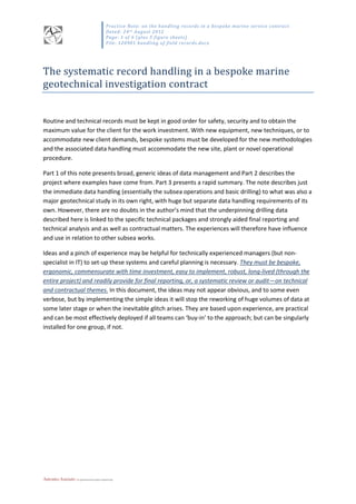
The drilling operation may be seen in Figure 1: Activities timeline in a typical drilling cycle
(excluding geotechnical and logging works). Each dive comprised three descending units: the
RovDrill3 drilling unit and two work-class ROVs for power, communications and drill-control via the
fixed Q6 and site inspection, support, additional sampling and video in Q5.
Data (file name convention) and directory structure models
As noted earlier the filenames and directory hierarchy will commonly have collections of: date, data
type, study location (site or hole), and often, source.
In this case Positions reflected the desired areas of interest which may or may not be investigated by
drilling or sampling but all were inspected by video and drilling sites were indexed only after drilling
was commenced. Therefore two positional data streams were often active during the works, P and
SD sites. The streams of data emerged in various formats and either requiring presentation or post-
processing. This gives rise to dive and survey data; drillers’ logs; various data plotted and in
specifically required database formats; core data; sediment sample data, videos and photographs.
Attendant indexes of receipt/approval/permission signatures were also collected. The scheme is
shown in Figure 2: Description of file naming convention and files were stored as collections on a
per site/borehole basis and a data-type basis as shown in Figure 3: Digital Data Filing System.
Once collected, each of the delivered data files is easily merged (automatically) into large data tables
which can then be interrogated. Several daily, weekly and summary reports are produced
systematically from various sets, but the main borehole summary report is shown in Figure 4:
Borehole cover sheet report. Multiple data packages are presented, tabulated and/or produced
graphically to create this report. This is an automatic process run entirely through macro controls in
Excel and can be generated and renewed for all data packages as required or as modifications or
new calculations are included.
The system is routinely controlled by a single page operated at print or production time (although
special routines exist on given sheets for auditing, testing and other administrative controls) as
shown in Figure 5: Borehole print report generator. Here, summary data can be checked and
reviewed and single and multiple reports can be printed or as digital copies (pdf).
7. SD#### - P#### - #### - YYMMDD - SITE . pdf
BOREHOLE
NUMBER(S)
(sequentialas
Nautilus)
LOCATION
NUMBER(P)
(providedby
NautilusinDive
Plan)
DATATYPEID
(ascodesbelow)
FILE
COMPILATION
DATE
isdateofdeliveryor
creationdate
STATUS
onvesselthisis
always:SITE
FINALREPORT
COMPILATIONIS
PDF
P#### - SD#### - #### - YYMMDD - SITE . pdf
SD####; SD000; or, SDX
applicable data type code Receive from Group Post-Processing needed? SCAN / CONVERT to PDF
1 DIP NMI Y N
2 DRL RovDrill typing Y
3a CSV RovDrill Y *.csv
3b CSVP TSM-RovDrill create plots Y
4 CMS NMI N Y
5 DRS UTEC N N
6 SIG TSM-NMI N Y
7 SED NMI ? N Y
8 RCF NMI N Y
9 VIC / VIP / VIS ROV ? N Y
"sequential.jpg"
filename from camera
TSM Y N
use SD filenames only TSM Y N
videos
use SD filenames on VIC
use P or PS filenames on
VIP & VIS
TSM Y N
C:UsersEdward AntonioDesktop[ReportFiguresDescription.xlsx]FileNaming
Deliverables File - Boreholes & Core Recovery
DESCRIPTION OF FILE NAMING CONVENTION
Sign Off Sheet
Core Measure Sheet
in Hole & Type & Image Folder
CSV Drill Plots
Survey Position Summary
Image FolderCore ImagesSD####
sub sections of file name are not limited in length but must be separated by "-" and in correct order.
A typical example being:
SD123-P456-RCF-110103-SITE.PDF
Also note that some work (e.g. video files) may refer only or primarily to a P (location) number.
In this case enter P first as:
P456-SD123-VIC-101101-SITE.PDF
Also, PS locations e.g. sediment sample sites which are remote from drilling sites, enter as:
PS123-SD000-VIS-101101-SITE.PDF
If multiple sites SD sites are referenced at the P location then leave SD reference as SDX
P123-SDX-VIS-101101-SITE.PDF
Recovery Final (post-analysis)
Video Handovers
[core, position, or, sediment videos]
... Core DeliverablesImage FolderContact PrintsSD123 Contact (9).pdf
... Core DeliverablesVideo FolderVICSD123-P456-VIC-110311-SITE.pdf
... Core DeliverablesType9 Video HandoversSD123-P456-VIP-110311-SITE.pdf
more examples
... Core DeliverablesHoleSD123SD123-P456-SIG-110311-SITE.pdf
... Core DeliverablesType2 DRL Drillers Log SheetsSD123-P456-DRL-110311-SITE.pdf
... Core DeliverablesImage FolderCore ImagesSD123image9999.jpg
... Core DeliverablesImage FolderWallet PrintsSD123 Wallet (35).pdf
... Core DeliverablesVideo FolderVIPP456-SD123-VIP-110311-SITE.pdf
... Core DeliverablesVideo FolderVISPS789-SDX-VIS-110311-SITE.pdf
S:Projects00004 Nautilus Seabed MiningVessel DocsAs built information and recordsCore Deliverables
root path to filing system
Video FolderVIC
Video FolderVIP
Video FolderVIS
Image FolderWallet Prints
Image FolderContact Prints
images
CSV Drilling Data
in Video Folder & TypeSED Recovery
S:Projects00004 Nautilus Seabed MiningVessel DocsAs built information and recordsCore Deliverables
Drillers Logs
Applicable Records to Collate
Dive Information Plan
SED Recovery
Images and Video files themselves are stored in:
FIGURE 2
8. folder description
… Core Deliverables
│ issued or
initiated by
valid file name
code
stored as file
type
├ Hole Folder Data on BOREHOLE basis
│ ├ SD165 each hole has a collection of sheets (one of each type) TSM
DIP DRL CSV CSVP
CMS DRS SIG SED
RCF
pdf, csv
│ ├ … each hole has a collection of sheets (one of each type) TSM
DIP DRL CSV CSVP
CMS DRS SIG SED
RCF
pdf, csv
│ └ … each hole has a collection of sheets (one of each type) TSM
DIP DRL CSV CSVP
CMS DRS SIG SED
RCF
pdf, csv
│├ Type Folder Data on TYPE basis
│ ├ DIP Dive Information Plan NMI DIP pdf
│ ├ DRL Typed Drillers Log (*3)
TSM DRL pdf
│ ├ CSV CSV Drill Data RovDrill CSV csv
│ ├ CSVP Plots of CSV Drill Data TSM CSVP pdf
│ ├ CMS Core Measurement Sheet (*1)
NMI CMS pdf
│ ├ DRS Survey Report UTEC DRS pdf
│ ├ SIG Signature Sign-off Sheet TSM SIG pdf
│ ├ SED Sediment Sample Measurement Sheet [SED### & tracking] TSM-Q5 SED### pdf
│ ├ RCF NMI MZ recovery sheet NMI RCF pdf
│ ├ Video Handover Video Handovers
│ │ ├ VIC IT core video handover sheet TSM VIC pdf
│ │ ├ VIP
pre-survey, landout and post videos handover per position or site (n.b.
some sites abandoned after pre-survey)
TSM VIP pdf
│ │ └ VIS
core video handover per sediment sample site (n.b. some sites are not
drilled or are specific to sampling)
TSM VIS pdf
│ ││ └ Image Handover Image Handover for core run sheet TSM per SD### pdf
│├ Image Folder Image Data on BOREHOLE basis
│ ├ Core Images Core Images
│ ├ ├ SD165 each core run of each borehole has one or more images TSM
as camera
filename
jpg
│ ├ ├ … each core run of each borehole has one or more images TSM
as camera
filename
jpg
│ ├ └ … each core run of each borehole has one or more images TSM
as camera
filename
jpg
│ ││ ├ Contact Prints contact prints of core images (35 per sheet) (*2)
TSM per SD### pdf
│ └ Wallet Prints Wallet prints of core images (9 per sheet) (*2)
TSM per SD### pdf
│└ Video Folder Video Data on BOREHOLE / POSITION basis
├ Core Video Core Video
│ ├ SD165 IT core video per borehole TSM-Q6
Video_TS
Video_RM
BUP,VOB, IFO
│ ├ … IT core video per borehole TSM-Q6
Video_TS
Video_RM
BUP,VOB, IFO
│ └ … IT core video per borehole TSM-Q6
Video_TS
Video_RM
BUP,VOB, IFO
│├ Position Video Position Video
│ ├ P123
pre survey, landout and post videos per position or site (n.b. not always of
sites of drilling as some sites abandoned)
TSM-Q5
Video_TS
Video_RM
BUP,VOB, IFO
│ ├ …
pre survey, landout and post videos per position or site (n.b. not always of
sites of drilling as some sites abandoned)
TSM-Q5
Video_TS
Video_RM
BUP,VOB, IFO
│ └ …
pre survey, landout and post videos per position or site (n.b. not always of
sites of drilling as some sites abandoned)
TSM-Q5
Video_TS
Video_RM
BUP,VOB, IFO
│└ Sample Video Sediment Sample at Position Video
├ P123
core video per sediment sample site (n.b. not always of sites of drilling as
some sites are not drilled or are specific to sampling)
TSM-Q5
Video_TS
Video_RM
BUP,VOB, IFO
├ …
core video per sediment sample site (n.b. not always of sites of drilling as
some sites are not drilled or are specific to sampling)
TSM-Q5
Video_TS
Video_RM
BUP,VOB, IFO
└ …
core video per sediment sample site (n.b. not always of sites of drilling as
some sites are not drilled or are specific to sampling)
TSM-Q5
Video_TS
Video_RM
BUP,VOB, IFO
*1 TSM make and keep own core record sheet also
*2 not required for handover - TSM use only
*3 hand written copies are maintained and provided at handover
C:UsersEdward AntonioDesktop[ReportFiguresDescription.xlsx]FolderStructure
root & path
Digital Data Filing System
FIGURE 3
11. Practice Note: on the handling records in a bespoke marine service contract
Dated: 24th August 2012
Page: 6 of 6 (plus 5 figure sheets)
File: 120901 handling of field records.docx
AntonioAssociates Ltd geotechnical project engineering
Part 3: Summary and review of benefits
Actual outcomes and further field processing and reporting
A system was finally developed and adopted which worked well and enabled all field data to be
collected and stored and then retrieved, at any stage and in any form, to provide analysis for daily
and final reporting. The system was systematic and streamlined by the use of macro-tools and local
batch coding to ensure the integrity of the data and to ease its routine manipulation for analysis.
This both speeded the daily process and provided quality assurance by avoiding inevitable human
errors during handling and made routine working practices much easier.
Implicit outcomes: audit trails, final reporting and post-processing benefits
Further benefits arose at a later stage when review and even claims issues arose in final reporting
and final accounts. Data was able to be reviewed in new ways, so as to demonstrate the impact of
different methods of measurement. Alternative assessments could then be compared with relative
ease and various scenarios were examined.
Further understanding also emerged. By maintaining the links between unprocessed data and final
reports it could be shown that given tooling produced different results to other, identical tools. This
then pointed the way to look, in some detail, at manufacturing and deployment issues which
otherwise would not have been evident.