Weitere ähnliche Inhalte
Ähnlich wie מאמר סופי (20)
מאמר סופי
- 1. Progress in low voltage reversible electrowetting
with lubricated polymer honeycomb substrates
Edward Bormashenko,*ab
Roman Pogreb,a
Yelena Bormashenko,a
Hadas Aharoni,b
Evgeny Shulzinger,*a
Roman Grinev,a
Daniel Rozenmanb
and Ziva Rozenmanb
Low-voltage electrowetting on liquid infused films realized with lubricated honeycomb polymer surfaces is
reported. Introduction of ethylene carbonate into the polymer (polycarbonate) matrix allowed an increase
in the sensitivity of the scheme. A theoretical analysis of the thermodynamics of the electrowetting on a
liquid infused film is reported. Fitting of experimental data to theoretical curves allowed an estimation of
the specific capacity of the double layer. An analysis of the viscous dissipation taking place under the
proposed electrowetting scheme is presented.
Introduction
An interest in the phenomenon of electrowetting was boosted in
the 1980s in the context of various applications of the effect,
including lab-on-chip systems1–4
and adaptive optical lenses.1–7
Electrowetting is already coming to fruition for many applica-
tions, such as display technologies, droplet transport, smart
optics, exible systems, remote switching, electronic paper,
miniaturized chemistry and energy harvesting.8
Numerous
applications of electrowetting were summarized in recent
reviews.8–10
However, the applications of electrowetting face a
serious problem: the voltages necessary for manifestations of this
effect are relatively high, on the order of magnitude of several
hundred volts.9,10
The important factor which adversely affects
electrowetting is the effect of the pinning of the triple line, leading
to high voltages necessary for electrical actuation of droplets.11
One of the most popular modern congurations of electrowetting
experiments is the so-called electrowetting-on-dielectric scheme
(EWOD), in which liquid is placed on an insulating layer on top of
bare electrodes.12–14
A detailed theoretical analysis of the EWOD
scheme was undertaken recently in ref. 14 and 15. A number of
groups reported low-voltage EWOD schemes,16–23
exploiting a
diversity of supporting dielectrics, including amorphous uo-
ropolymers,16
solid-like ionic liquids,17
parylene,21
etc.
However, the EWOD scheme also suffers from the effect of
the pinning of the triple line.11
It was demonstrated recently
that the impact of pinning may be essentially decreased when
liquids are used as the dielectric layer.24,25
Wang et al. coined for
this scenario of electrowetting the abbreviation EWOLF, which
means electrowetting on liquid-infused lm.25
Our paper is
devoted to the further development of a low-voltage EWOLF
scheme, enabling an essential decrease in the voltage necessary
for the onset of electrical actuation of droplets.
Experimental
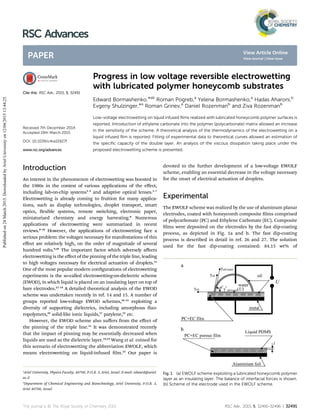
The EWOLF scheme was realized by the use of aluminum planar
electrodes, coated with honeycomb composite lms comprised
of polycarbonate (PC) and Ethylene Carbonate (EC). Composite
lms were deposited on the electrodes by the fast dip-coating
process, as depicted in Fig. 1a and b. The fast dip-coating
process is described in detail in ref. 26 and 27. The solution
used for the fast dip-coating contained: 84.15 wt% of
Fig. 1 (a) EWOLF scheme exploiting a lubricated honeycomb polymer
layer as an insulating layer. The balance of interfacial forces is shown.
(b) Scheme of the electrode used in the EWOLF scheme.
a
Ariel University, Physics Faculty, 40700, P.O.B. 3, Ariel, Israel. E-mail: edward@ariel.
ac.il
b
Department of Chemical Engineering and Biotechnology, Ariel University, P.O.B. 3,
Ariel 40700, Israel
Cite this: RSC Adv., 2015, 5, 32491
Received 7th December 2014
Accepted 19th March 2015
DOI: 10.1039/c4ra15927f
www.rsc.org/advances
This journal is © The Royal Society of Chemistry 2015 RSC Adv., 2015, 5, 32491–32496 | 32491
RSC Advances
PAPER
Publishedon24March2015.DownloadedbyArielUniversityon12/04/201513:44:25.
View Article Online
View Journal | View Issue
- 2. dichloromethane (CH2Cl2), 10.11 wt% of chloroform (CHCl3),
3.9 wt% of PC and 1.83 wt% of EC. The higher concentrations of
EC led to formation of defective micro-porous structures. The
fast dip-coating carried out under the relative humidity (RH) of
40–50% gave rise to the “breath-gures” self-assembly, reviewed
recently in ref. 28–30. PC is distinguished by its high dielectric
constant (3 ¼ 2.9) and dielectric strength (150 kV cmÀ1
).
A typical self-assembly pattern resulting from the breath-
gures self-assembly, formed on aluminum plates, is depicted
in Fig. 2. The average radius of pores was about 1.5 mm. The
average depth of pores as established by AFM was about 1 mm.
PC porous coatings were impregnated by the polydimethylsi-
loxane (PDMS) oil for MP&BP apparatus, for brevity called
hereaer “silicone oil” (supplied by Sigma-Aldrich). This kind of
oil was chosen due to its high dielectric strength (120 kV cmÀ1
)
and low viscosity (hoil y 5 Â 10À2
Pa s). For the purpose of
uniform spreading of the oil, the lubricated substrates were
heated to 60
C, and aerwards cooled to ambient temperature.
The thickness of the oil layer was established by weighing as l y
20 Æ 2 mm (see Fig. 1b), which is much larger than the depth of
the pores. The physical properties of the silicone oil relevant to
our study are summarized in Table 1. Experiments were carried
out with 8 ml bi-distilled water droplets. Droplets were visualized
with a Ram´e-Hart Advanced Goniometer, Model 500-F.
The surface tension of the silicone oil was established by the
pendant drop method with a Ram´e-Hart Advanced Goniometer,
Model 500-F.
Theoretical analysis of the EWOLF electrowetting scheme
In the EWOLF scheme, a water droplet is deposited on the oil
layer.24,25
The wetting regime is governed by the spreading
parameter S, given by:
S ¼ g À (goil + goil/water), (1)
where g ¼ 71
mJ
m2
; goil ¼ 21
mJ
m2
and goil=water ¼ 23 À 24
mJ
m2
are
interfacial tensions at the water/vapor, oil/vapor and oil/water
interfaces respectively (goil was established experimentally as
described in the Experimental section; goil/water was extracted
from the literature data31
). Substituting the aforementioned
values in exp. (1), we obtain S 0; in this case, the silicone oil is
expected to coat the water droplet.24,32–34
Indeed, the formation
of the silicone oil layer coating the droplet was observed
experimentally.
Thus, the actual wetting regime displayed schematically in
Fig. 1a, illustrated in Fig. 3, and discussed recently in detail in
ref. 33–35, is rather intricate. The situation is complicated by
the “wetting ridges” formed in the vicinity of the contact line,
discussed in ref. 33 and 34 and shown schematically in Fig. 3.
The complicated shape of the water/vapor interface, exhibiting
a ex point, is noteworthy, making an accurate measurement
and interpretation of the contact angle quite challenging. For
the analysis of the wetting situation, we implemented the
following experimental procedure. We experimentally estab-
lished the contact diameter 2a changing with a voltage U by
means of a traditional goniometric procedure, and we inter-
preted the dependence a(U), as will be discussed below.
Consider the free energy G of a water droplet deposited on
the silicone layer and exposed to the voltage U, as described in
Fig. 1a and b and 3 (the energy of the “wetting ridge” is
neglected):
G
Â
hðx; yÞ
Ã
¼
ðð
S
À
goil þ goil=water þ PðeÞ
Á ffiffiffiffiffiffiffiffiffiffiffiffiffiffiffiffiffiffiffiffiffiffiffiffi
ð1 þ ðVhÞÞ2
q
þ
g*
oil=waterðUÞ À goil
!
dxdy; (2)
where g*
oil/water(U) is the surface energy of the oil/water interface
exposed to voltage U, e is the thickness of the PDMS liquid layer
coating a water droplet (see Fig. 3), h(x, y) is the local height of
the liquid surface above the point (x, y) of the substrate (it is
supposed latently that there is no difference between surface
tensions and surface energies for goil, goil/water), and the integral
is extended over the wetted substrate area. The rst term of the
integrand presents the capillary energy of the liquid
“composite” cap. It should be stressed that this energy is not
modied by voltage. The second term describes the change in
the energy of the oil/water interface modied by voltage, and it
is usually related to the formation of the Helmholtz double
layer.10,36–38
P(e) is the term resulting from the disjoining pres-
sure P(e) (see ref. 36–39).
PðeÞ ¼ À
dP
de
: (3)
Fig. 2 Composite honeycomb coating built from polycarbonate and
ethylene carbonate, deposited on Al plain electrodes obtained with
“breath-figures” self-assembly, carried out in a humid atmosphere.
Scale bar is 1 mm.
Table 1 Physical properties of the silicone oil used in the investigation
Oil
Viscosity,
h, Pa s
Surface tension, goil,
mJ mÀ2
Interface tension,
goil/water mJ mÀ2
Density, r,
103
kg mÀ3
Dielectric
constant, 3
Silicone oil 0.05 21 23–24 0.963 2.5
32492 | RSC Adv., 2015, 5, 32491–32496 This journal is © The Royal Society of Chemistry 2015
RSC Advances Paper
Publishedon24March2015.DownloadedbyArielUniversityon12/04/201513:44:25.
View Article Online
- 3. Gravity is neglected, because it has no inuence on the
apparent contact angle (abbreviated APCA).39
If we restrict
ourselves to an axially symmetric “coated” droplet (shown in
Fig. 3), the free energy G is given by the following expression:
G
À
h; h0
Á
¼
ða
0
h
2p
À
goil þ goil=water þ PðeÞ
Á
x
ffiffiffiffiffiffiffiffiffiffiffiffiffiffi
1 þ h02
p
þ 2px
g*
oil=waterðUÞ À goil
i
dx; (4)
where a is the contact radius of the droplet (see Fig. 3). We also
suppose that the PDMS coated water droplet does not evaporate
(this assumption is well-justied, because PDMS actually does
not evaporate); thus, the condition of the constant volume V
should be considered as:
V ¼
ða
0
2pxhðxÞdx ¼ const: (5)
It should be stressed that in the discussed experimental
situation, where a water droplet is coated with oil, the volume of
the droplet is constant.
Thus, the problem is reduced to the minimization of the
functional:
G
À
h; h0
Á
¼
ða
0
~G
À
h; h0
; x
Á
dx; (6a)
~G
À
h; h0
; x
Á
¼ 2p
À
goil þ goil=water þ PðeÞ
Á
x
ffiffiffiffiffiffiffiffiffiffiffiffiffiffi
1 þ h02
p
þ 2px
g*
oil=waterðUÞ À goil
þ 2plxh; (6b)
where l is the Lagrange multiplier to be deduced from exp. (5).
If the endpoints of the contact line are free to move, the
transversality condition at the endpoint a yields:40
~G À h0 ~G
0
h0
x¼a
¼ 0; (7)
where ~G
0
h0 denotes the h0
derivative of ~G. The procedure,
described in detail in ref. 39, yields for the apparent contact
angle:
cos q* ¼
goil À g*
oil=waterðUÞ
goil þ goil=water þ PðeÞ
: (8)
It is plausible to suggest that the change in the oil/water
interfacial tension due to the voltage U is (as it occurs for
solid dielectrics10,36,38
) is described by:
g*
oil=waterðUÞ ¼ goil=water À
CU2
2
; (9)
where C is the specic capacity of the double layer, which is
inherent to the EWOLF scheme.8–10
The thermodynamic justi-
cation of eqn (9) is presented in ref. 41. Substituting exp. (9)
into exp. (8), and considering cos q ¼
goil À goil=water
goil þ goil=water þ PðeÞ
(where q is the equilibrium contact angle of the system corre-
sponding to the zero voltage situation35
) results in the following
expressions:
cos q* ¼ cos q þ
CU2
2
À
goil þ goil=water þ PðeÞ
Á ¼ cos q þ aU2
; (10a)
a ¼
C
2
À
goil þ goil=water þ PðeÞ
Á ; (10b)
resembling the well-known Lippmann equation of electro-
wetting.10,32,42,43
Exp. (10) leads to the expectable conclusion: the
high sensitivity of the EWOLF scheme calls for high specic
capacities C. Thus, a low-voltage EWOLF scheme should fulll
two main demands: low contact angle hysteresis,11,44,45
and the
highest possible specic capacitances of the double layer C.
The rst demand is fullled due to the fact that polymer
substrates impregnated by oils demonstrate very low contact
angle hysteresis.24,25,33,34,46–52
Further progress in the develop-
ment of low-voltage schemes may be obtained by increasing the
specic capacitance C. For this purpose, ethylene carbonate
(EC) was introduced into the PC matrix. The molecule of EC is
characterized by an abnormally high molecular dipole moment
of 4.9 D, leading to a dielectric constant as high as 90.53,54
Thus,
an essential increase in the specic capacity C results in a
decrease of the voltage necessary for electrowetting actuation of
droplets. It should be stressed that in our experiments, water
soluble EC is isolated from water by the layer of PDMS, as
depicted in Fig. 1.
Experimental results
We established that PC + EC silicone oil-impregnated honey-
comb surfaces demonstrated low-voltage DC electrowetting,
illustrated by Fig. 4–6. Fig. 4 depicts the distortion of the water
droplet under applied voltage. Wetting ridges formed in the
vicinity of the triple line are clearly seen.33,34
The presence of
wetting ridges makes accurate measurement of the apparent
contact angles predicted by exp. (10) problematic, due to the
complicated shape of the water/vapor interface, exhibiting a ex
point.
At the same time, the relative maximal displacement of the
triple line Da/a0 may be accurately established experimentally
with a goniometer. Fig. 5 depicts the dependence of the relative
maximal displacement of the triple line as a function of the
applied voltage U.
It is recognized from the data, displayed in Fig. 5, that the
onset of the displacement of the triple line starts at the voltage
of U0 ¼ 5 V. This voltage is markedly lower than the voltages
reported in ref. 24 and 25, and it is reasonable to relate the
progress in the decrease of the voltage necessary for
Fig. 3 Parameters of the wetting regime for water droplets deposited
on the silicone oil layer. q* is the apparent contact angle.
This journal is © The Royal Society of Chemistry 2015 RSC Adv., 2015, 5, 32491–32496 | 32493
Paper RSC Advances
Publishedon24March2015.DownloadedbyArielUniversityon12/04/201513:44:25.
View Article Online
- 4. electrowetting actuation of droplets to the essential increase in
the specic capacity of the scheme, achieved by introducing EC
into the polymer matrix. The EWOLF scheme remained
reversible up to threshold voltages of 50 V.
It is reasonable to quantify the sensitivity of the EWOLF
scheme by the parameter x ¼ Da/a0U, as proposed in ref. 24. It is
recognized from the experimental data that x y 3.6 Â 10À3
VÀ1
for the EWOLF scheme exploiting PC + EC silicone
oil-impregnated honeycomb surfaces, which is markedly larger
than that reported in ref. 24 for pure PC substrates (x y 1.3 Â
10À3
VÀ1
). This means that the presented scheme is more
sensitive to the voltage than that reported in our previous paper.
The essential improvement of the sensitivity of the electro-
wetting scheme is reasonably related to the increase of the
dielectric constant of the double layer stipulated by the intro-
duction of EC, resulting in an increase in the specic capacity
appearing in ref. 10. However, the quantitative analysis of the
experimental data is far from trivial. Indeed, exp. (10a and b)
predict the apparent contact angle, whereas the experimental
procedure allows accurate establishment of the relative
maximal displacement of the triple line Da/a0. Assuming that
the droplet exposed to voltage keeps the shape of a spherical
cap, accepting the constancy of the droplet's volume V and
applying the well-known geometrical relations, supplied by exp.
(11a and b):
V ¼
p
3
R3
ð1 À cos qÞ2
ð2 þ cos qÞ (11a)
a ¼ R sin q, (11b)
(where R is the radius of a droplet), yields the following
expression for the relative maximal displacement of the triple
line, yields the following:
Da=a0 ¼
1 À cos q
1 À cos q*
2
3
2 þ cos q
2 þ cos q*
1
3 sin q*
sin q
À 1: (12)
Fitting of the experimental data by the cumbersome function
supplied by exp. (10) and (12) is presented in Fig. 5. The value of
a (see exp. (10b)) was considered a tting parameter. The best
possible tting (carried out with Origin 8.1 soware) was
obtained for a y 6 Â 10À5
VÀ2
. This makes possible a rough
estimation of the specic capacitance of the double layer
C. Indeed, if the effects due to the disjoining pressure are
negligible, we have:
C y 2a(goil + goil/water). (13)
Substituting the abovementioned values of a, goil and goil/water
into exp. (3) yields: Cy5
mF
m2
: This value is smaller than the
specic capacitances reported for EWOD schemes55,56
and typical
specic capacities inherent for double layers,37
and this
discrepancy calls for future investigations.
It should be emphasized that tting of experimental data by
exp. (12) is possible only at the initial section of the experi-
mental curve, i.e. at relatively low voltages. At higher voltages of
100 V, the effect of saturation of the contact angle was observed,
which is still not understood to its full extent.57
The dynamics of the EWOLF scheme
When the triple line is displaced, viscous dissipation occurs in
the water droplet and also within the oil layer. Both of the
viscous dissipations (accurately speaking, the velocities of the
viscous dissipations) are given by exp. (14) (see ref. 58):
dEvisc
dt
¼ h
ð
Vd
V~u
2
dV: (14)
Here Vd is the volume over which viscous dissipation occurs,
h is the viscosity of the liquid, and ~u is the velocity eld in the
liquid.58
Assuming ðV~uÞ2
y
vu
vy
2
(y is the vertical axis), we have
for the viscous dissipation in the droplet
dEwater
dt
(recall that the
volume of the spherical segment is given by:
V ¼ pH2
a À
1
3
H
; a is the contact radius, and H is the height
of a spherical segment, shown in Fig. 3):
Fig. 5 Relative maximal displacement of the triple line Da/a0 vs.
applied DC voltage U for the EWOLF scheme studied in the investi-
gation. Solid line represents the fitting of the experimental data by the
function, given by exp. (10) and (12).
Fig. 4 Electrowetting of silicone oil-lubricated PC + EC substrates.
Volume of the water droplet is 8 ml. (a) U ¼ 0 V; (b) U ¼ 55 V.
32494 | RSC Adv., 2015, 5, 32491–32496 This journal is © The Royal Society of Chemistry 2015
RSC Advances Paper
Publishedon24March2015.DownloadedbyArielUniversityon12/04/201513:44:25.
View Article Online
- 5. dEwater
dt
¼ hwater
ð
Vd
vu
vy
2
dVyhwater
u2
H2
pH2
a À
1
3
H
¼ phwateru2
a À
1
3
H
: (15)
For the viscous dissipation
dEoil
dt
taking place within the oil
layer, we have:
dEoil
dt
¼ hoil
ð
Vd
vu
vy
2
dVyhoil
u2
l2
pa2
l ¼ phoilu2a2
l
; (16)
where l is the thickness of the silicone oil layer, shown in
Fig. 1b. Combining exp. (15) and (16) yields:
Ewater
Eoil
y
hwater
hoil
a À
1
3
H
l
a2
: (17)
In our experiments a y H takes place; this assumption gives
rise to the following simple estimation:
Ewater
Eoil
y
hwater
hoil
l
a
: (18)
In our experiments: hoil y 5 Â 10À2
Pa s; hwater y 10À3
Pa s;
l y 20 Â 10À6
m; a y 10À3
m. Thus, we obtain:
Ewater
Eoil
y
10À3
5 Â 10À2
20 Â 10À6
10À3
¼ 4 Â 10À4
: This means, that in
our experiments, the viscous dissipation is totally governed
by the dissipation occurring in the silicone oil layer. In our
estimation, we assumed that the thickness of the silicone oil
layer is close to its initial value. However, the thickness of the
oil layer essentially changes aer loading a water droplet on
its surface; it may be as low as 20 nm.59
Considering this
observation strengthens the conclusion that the viscous
dissipation is controlled by the processes taking place in the
oil layer.
The balance of interfacial and viscous forces acting within
the silicone oil layer yields (see ref. 18):
v y
2lDgðUÞ
hoila
; (19)
where v is the velocity of the triple line, and Dg(U) is the
non-equilibrium, specic interfacial force depending on
the applied voltage U. Combining exp. (19) and (9) results in
the following “naive” scaling law: v $ U2
. The experimental
dependence of the velocity of the triple line v on the
applied voltage U is depicted in Fig. 6. The double
logarithmic plot, ln v vs. ln U (presented in Fig. 6) is reason-
ably tted with a straight line with a slope in the range of
1.8–2.2, supporting the square scaling law resulting from
exp. (19) and (9).
The further progress in the improvement of the sensitivity of
the EWOLF scheme may be related to the increasing of the
specic capacity C, exploiting of extremely low viscosity oils (see
eqn (19)) and improvement of the polymer layer, preventing the
charge leakage, as discussed in ref. 60.
Conclusions
We conclude that impregnated porous polymer substrates
demonstrate a potential for low-voltage electrowetting. Elec-
trowetting on liquid-infused lms allows low-voltage actuation
of droplets, due to the low contact angle hysteresis inherent for
liquid/liquid interfaces. We reported that introducing ethylene
carbonate, (characterized by a very high dielectric constant) into
the porous polymer lm enabled an increase of the sensitivity of
the electrowetting scheme to the applied voltage. Voltages as
low as 5 V gave rise to the onset of displacement of the contact
line. It is reasonable to relate the high sensitivity of the reported
electrowetting scheme to the high specic capacity of the
Helmholtz double layer. A theoretical analysis of the electro-
wetting on a liquid-infused polymer lm was reported. An
explicit equation predicting the apparent contact angle was
derived. The specic capacity of the double layer C was calcu-
lated. The dynamics of the EWOLF scheme was analyzed. The
viscous dissipation occurring under EWOLF is controlled by the
processes taking place in the oil layer.
Acknowledgements
The Authors are grateful to Professor Gene Whyman for
extremely fruitful discussions. The Authors are thankful to Mrs
Albina Musin for her inestimable help in preparing this
manuscript, and to Mrs Natalya Litvak for her kind help in SEM
imaging.
References
1 S. K. Cho, H. J. Moon and C. J. Kim, J. Microelectromech. Syst.,
2003, 12, 70–80.
2 M. G. Pollack, R. B. Fair and A. D. Shenderov, Appl. Phys.
Lett., 2000, 77, 1725.
Fig. 6 Average velocity of the triple line v (m sÀ1
) vs. applied voltage U
(V) for the EWOLF scheme. The best fitting is presented by the straight
line with a slope of 1.8, represented by the solid line.
This journal is © The Royal Society of Chemistry 2015 RSC Adv., 2015, 5, 32491–32496 | 32495
Paper RSC Advances
Publishedon24March2015.DownloadedbyArielUniversityon12/04/201513:44:25.
View Article Online
- 6. 3 V. Srinivasan, V. K. Pamula and R. B. Fair, Lab Chip, 2004, 4,
310–315.
4 R. B. Fair, Microuid. Nanouid., 2007, 3, 245–281.
5 B. Berge and J. Peseux, Eur. Phys. J. E: So Matter Biol. Phys.,
2000, 3, 159–163.
6 S. Kuiper and B. H. W. Hendriks, Appl. Phys. Lett., 2004, 85,
1128–1130.
7 B. H. W. Hendriks, S. Kuiper, M. A. J. van As, C. A. Renders
and T. W. Tukker, Opt. Rev., 2005, 12, 255–259.
8 S. Arscott, RSC Adv., 2014, 4, 29223–29238.
9 W. C. Nelson and C. J. Kim, J. Adhes. Sci. Technol., 2012, 26,
1747–1771.
10 L. Chen and E. Bonaccurso, Adv. Colloid Interface Sci., 2013,
210, 2–12.
11 R. Gupta, D. M. Sheth, T. K. Boone, A. B. Sevilla and
J. Frechette, Langmuir, 2011, 27, 14923–14929.
12 B. Berge, C. R. Acad. Sci., Ser. II: Mec., Phys., Chim., Sci. Terre
Univers, 1993, 317, 157–163.
13 I. Moon and J. Kim, Sens. Actuators, A, 2006, 130–131, 537–
544.
14 W. Da and Y.-P. Zhao, Int. J. Nonlinear Sci. Numer. Simul.,
2007, 8, 519–526.
15 F. Yang and Y.-P. Zhao, J. Phys. Chem. C, 2014, 118, 26859–
26865.
16 E. Seyrat and R. A. Hayes, J. Appl. Phys., 2001, 90, 1383.
17 X. Zhang and Y. Cai, Angew. Chem., 2013, 125, 2345–2348.
18 F. He and S. R. Nugen, Microuid. Nanouid., 2014, 16, 879–
886.
19 N. Yang, X. Liu, X. Zhang, B. Lin, H. Yin, Z. Kou, Y. Ding and
J. Zhu, Sens. Actuators, A, 2014, 219, 6–12.
20 I. F. Guha, J. Kedzierski and B. Abedian, Appl. Phys. Lett.,
2011, 99, 024105.
21 M. Dhindsa, S. Kuiper and J. Heikenfeld, Reliable and low-
voltage electrowetting on thin parylene lm, Thin Solid
Films, 2011, 519, 3346–3351.
22 Y.-Y. Lin, R. D. Evans, E. Welch, B.-N. Hsu, A. C. Madison and
R. B. Fair, Sens. Actuators, B, 2010, 150, 465–470.
23 P. T. C. Lee, C.-W. Chiu, T.-M. Le, T.-Y. Chang, M.-T. Wu,
W.-Y. Cheng, S.-W. Kuo and J.-J. Lin, ACS Appl. Mater.
Interfaces, 2013, 5, 5914–5920.
24 E. Bormashenko, R. Pogreb, Ye. Bormashenko, R. Grynyov
and O. Gendelman, Appl. Phys. Lett., 2014, 104, 171601.
25 C. Hao, Y. Liu, X. Chen, Y. He, Q. Li, K. Y. Li and Z. Wang, Sci.
Rep., 2014, 4, 6846.
26 E. Bormashenko, R. Pogreb, O. Stanevsky, Y. Bormashenko,
Y. Socol and O. Gendelman, Polym. Adv. Technol., 2005, 16,
299–304.
27 E. Bormashenko, A. Malkin, A. Musin, Y. Bormashenko,
G. Whyman, N. Litvak, Z. Barkay and V. Machavariani,
Macromol. Chem. Phys., 2008, 209, 567–576.
28 L. Xue, J. Zhang and Y. Han, Prog. Polym. Sci., 2012, 37, 564.
29 M. Hern´andez-Guerrero and M. H. Stenzel, Polym. Chem.,
2012, 3, 563.
30 Ed. Bormashenko, S. Balter and D. Aurbach, Macromol.
Chem. Phys., 2012, 213, 1742–1747.
31 P. Than, L. Prezosi, D. D. Joseph and M. Arney, J. Colloid
Interface Sci., 1988, 124, 552–559.
32 E. Bormashenko, A. Musin, Y. Bormashenko, G. Whyman,
R. Pogreb and O. Gendelman, Macromol. Chem. Phys.,
2007, 208, 702–709.
33 D. Smith, R. Dhiman, S. Anand, E. Reza-Garduno,
R. E. Cohen, G. H. McKinley and K. K. Varanasi, So
Matter, 2013, 9, 1772–1780.
34 S. Anand, A. T. Paxson, R. Dhiman, J. D. Smith and
K. K. Varanasi, ACS Nano, 2012, 6, 10122–10129.
35 V. Multanen, G. Chaniel, R. Grynyov, R. Y. Loew, N. K. Siany
and Ed. Bormashenko, Colloids Surf., A, 2014, 461, 225–230.
36 H. Y. Erbil, Surface Chemistry of Solid and Liquid Interfaces,
Blackwell, Oxford, 2006.
37 J. N. Israelachvili, Intermolecular and Surface Forces, Elsevier,
Amsterdam, 3rd edn, 2011.
38 P. G. de Gennes, F. Brochard-Wyart and D. Qu´er´e, Capillarity
and Wetting Phenomena, Springer, Berlin, 2003.
39 E. Bormashenko, Wetting of Real Surfaces, de Gruyter, Berlin,
2013.
40 I. M. Gelfand and S. V. Fomin, Calculus of Variations, Dover,
2000.
41 F. Mugele and J.-C. Baret, J. Phys.: Condens. Matter, 2005, 17,
R705.
42 E. Bormashenko, Math. Modell. Nat. Phenom., 2012, 7, 1–5.
43 E. Bormashenko, Chem. Phys. Lett., 2014, 599, 139–141.
44 F. Li and F. Mugele, Appl. Phys. Lett., 2008, 92, 244108.
45 H. J. J. Verheijen and M. W. J. Prins, Langmuir, 1999, 15,
6616–6620.
46 P. Kim, M. J. Kreder, J. Alvarenga and J. Aizenberg, Nano
Lett., 2013, 13, 1793–1799.
47 C. Shillingford, N. MacCallum, T.-S. Wong, P. Kim and
J. Aizenberg, Nanotechnology, 2014, 25, 014019.
48 T.-S. Wong, S. H. Kang, S. K. Y. Tang, E. J. Smythe,
B. D. Hatton, A. Grinthal and J. Aizenberg, Nature, 2011,
477, 443–447.
49 M. Nosonovsky, Nature, 2011, 477, 412–413.
50 S. Sunny, N. Vogel, C. Howell, T. L. Vu and J. Aizenberg, Adv.
Funct. Mater., 2014, 24, 6658–6667.
51 R. Tadmor, Langmuir, 2004, 20, 7659–7664.
52 M. Nosonovsky, J. Chem. Phys., 2007, 126, 224701.
53 Y. Chernyak, J. Chem. Eng. Data, 2006, 51, 416–418.
54 R. Payne and I. E. Theodorou, J. Phys. Chem., 1972, 76, 2892–
2900.
55 S. Arscott, Sci. Rep., 2011, 1, 184.
56 H. Shintaku, Y. Tatara and S. Kawano, J. Fluid Sci. Tech.,
2009, 4, 636–647.
57 V. Peykov, A. Quinn and J. Ralston, Colloid Polym. Sci., 2000,
278, 789–793.
58 L. D. Landau and E. M. Lifshitz, Fluid Mechanics, Volume 6 of
A Course of Theoretical Physics, Butterworth-Heinemann,
Oxford, 1987.
59 A. Staicu and F. Mugele, Phys. Rev. Lett., 2006, 97, 167801.
60 M. Khodayari, J. Carballo and N. B. Crane, Mater. Lett., 2012,
69, 96–99.
32496 | RSC Adv., 2015, 5, 32491–32496 This journal is © The Royal Society of Chemistry 2015
RSC Advances Paper
Publishedon24March2015.DownloadedbyArielUniversityon12/04/201513:44:25.
View Article Online