Application of sensors : Thermistors and potentiometer

Application of sensors Applications of potentiometer: 1. Audio Control The potentiometer is used in radio and television (TV) receiver for volume control, tone control and linearity control. 2. Continuous Balance DVM – The basic block diagram of a servo balancing potentiometer type DVM The input voltage is applied to one side of a mechanical chopper comparator, the other side being connected to the variable arm of a precision potentiometer. 3. Lighting We can use a potentiometer to control the lighting level of a television, or the brightness of a computer screen. RTD 1.Air and Gas Temperature Measurement with RTD Sensors 2.liquids Temperature Measurement with Flexible RTDs The RTD temperature sensors are more accurate and precise then normally used temperature sensors and uses resistance concept to detect the temperature and convert to the digital value. THERMISTOR 1.NTC Thermistors For Cooling Applications ((PCB) 2. Thermistors Temperature Detection in Fire Alarms. The most cost effective fire alarm is one utilizing the thermistor method.

Empfohlen
Weitere ähnliche Inhalte
Was ist angesagt?
Was ist angesagt? (20)
Ähnlich wie Application of sensors : Thermistors and potentiometer
Ähnlich wie Application of sensors : Thermistors and potentiometer (20)
Mehr von Anaseem Hanini
Mehr von Anaseem Hanini (12)
Kürzlich hochgeladen
Kürzlich hochgeladen (20)
Application of sensors : Thermistors and potentiometer
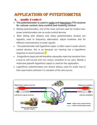
- 1. Applications of potentiometer 1. Audio Control The potentiometer is used in radio and television (TV) receiver for volume control, tone control and linearity control. Sliding potentiometers, one of the most common uses for modern low- power potentiometers are as audio control devices. Both sliding pots (faders) and rotary potentiometers (knobs) are regularly used to frequency attenuation, adjust loudness and for different characteristics of audio signals. The potentiometer with logarithmic taper, is often used in audio volume control devices, this is so because our hearing has a logarithmic response to sound pressure.1* A logarithmic taper pot will therefore natuarally make the transition from a loud to soft sound( and vice versa), smoother to our ears. Mostly a motorized pot(with logarithmic taper) is used for this application. Logarithmic potentiometers are almost always used for audio due to their asymmetric behavior if a variation of the axis occurs.
- 2. 2. Continuous Balance DVM – The basic block diagram of a servo balancing potentiometer type DVM The input voltage is applied to one side of a mechanical chopper comparator, the other side being connected to the variable arm of a precision potentiometer. The output of the chopper comparator, which is driven by the line voltage at the line frequency rate, is a square wave signal whose amplitude is a function of the difference in voltages connected to the opposite side of the chopper. The square wave signal is amplified and fed to a power amplifier, and the amplified square wave difference signal drives the arm of the potentiometer in the direction needed to make the difference voltage zero. The servo-motor also drives a mechanical readout, which is an indication of the magnitude of the input voltage. This DVM uses the principle of balancing, instead of sampling, because of mechanical movement. The average reading time is 2 s.
- 3. 3. Lighting We can use a potentiometer to control the lighting level of a television, or the brightness of a computer screen. Controlling the light level of an LED (light emitting diode) By using a variable resistor, the current can be controlled at will to either dim or brighten an LED or lamp in a circuit. The variable resistor in an electronic circuit is called a potentiometer. Attach the free end of the positive battery lead to either the right or left potentiometer lead. Use the right side lead if you want to increase resistance by turning the knob clockwise. Use the left side lead if you want to increase resistance by turning the knob counterclockwise. The circuit is now complete. Slowly turn the variable resistor knob clockwise and counterclockwise and observe how the LED brightens and dims. You are now controlling the light level of an LED.2*
- 4. RTD 1.Air and Gas Temperature Measurement with RTD Sensors Air and gas stream measurements are a challenge because the rate of transfer of temperature from the fluid to the sensor is slower than for liquids. Therefore, sensors specifically designed for use in air or gas place the sensing element as close to the media as possible. These Air Temperature RTD Sensors allow the sensing element to be nearly in direct contact with the air stream. With a housing design containing lots that allow the air to flow past the element, this construction is very popular in measuring air temperature in laboratories, clean rooms, and other locations. When the situation requires a little more protection for the sensor, an option is to use a design similar to the RTD-860. This design has a small diameter probe with a flange for mounting. The configuration will be a little slower to respond to changes in the air stream, but it will provide improved protection for the sensor.
- 5. 2.liquids Temperature Measurement with Flexible RTDs The RTD temperature sensors are more accurate and precise then normally used temperature sensors and uses resistance concept to detect the temperature and convert to the digital value. flexible RTD inserted beneath the insulating blanket. Two leadwires form the only route for heat loss. As long as the pipe has sufficient insulation, its outside surface temperature agrees with the fluid inside. exposing a flexible RTD to outside air will reduce its accuracy. A flexible RTD reacts to temperature changes more quickly than a probe inside a brass thermowell. An even larger difference would be expected in comparison to a stainless steel thermowell. flexible RTDs work well to measure liquid temperature in pipes because they include flexible sensors that conform tightly to the surface. There are no air gaps to block heat transfer.
- 6. Thin electrical insulation reduces the thermal gradient between the sensing element and sensed surface. the element winding senses temperature over a sensed surface area. If you must retrofit a temperature sensor for your process piping, consider a flexible RTD. THERMISTOR 1.NTC Thermistors For Cooling Applications ((PCB) EVGA introduced Negative Temperature Coefficient (NTC) thermistors to its Printed Circuit Board (PCB).
- 7. These NTC thermistors express large decreases in resistance in response to small increases in detected temperature. The NTC thermistors are used to limit current at lower temperatures in order to control the VRM fan RPM. The fan would be slow or even idling at power on. As temperature increases, the thermistors allow more current to flow through the circuit, thus speeding up the fans and allowing for increased cooling.4* 2. Thermistors Temperature Detection in Fire Alarms. The most cost effective fire alarm is one utilizing the thermistor method. NTC Thermistors are ideal for detecting small changes in temperature,Because of their high sensitivity. Thermistors are temperature-sensing elements made of semiconductor material that displays large changes in
- 8. resistance in proportion to small changes in temperature. thermistors only require heat to activate. a Wheatstone bridge is used in out of balance where the out-of-balance voltage, ΔV, can be measured and related to the resistance of the thermistor. When the potential (voltage) P1 is the same as potential P2, the bridge is said to be balanced. Thermistor temperature detection doesn’t require smoke to activate and has fewer false alarms. The thermistor uses the ambient temperature of a building and will only activate when that temperature increases exponentially. there would be fewer false alarms and a quicker alert rate. An alternate circuit to measure temperature with a thermistor is by using a Wheatstone Bridge. Thermistor fire alarms can be placed in: 1. areas with high steam, such as used in dairy factories.
- 9. 2. Incineration and oven rooms where smoke usually gathers. 3. rooms with high temperatures like welding workshops. 4. industrial workplaces with a lot of dust and smoke. Strain gauges Strain gauges are used to keep rails in good condition. These strain gauges are put on the rails in a vertical, longitudinal,and lateral positions to measure different forces. The gauges go on the top, bottom, and sides of the rail. Just like the smart bridges,these sensors are used to maintain good conditions to the rails.
- 10. The train goes over the rails and trigger the sensors. The data is measured and appropriate action is taken to fix the rails if needed. This information would be useful to railroad maintenance workers. Strain gauges will be installed on the rail and the rail-seatto measure the vertical wheel load. A total of sixteen (16) straingauges will be installed per instrumented track transition. this Figure shows the picture of a rail section instrumented with “weld-able” strain gauges for measuring vertical wheel loads.
- 11. * the web bending method both measure the vertical forces in by means of attaching the vertical gauges to the web of the rail. * the web bending method measures lateral forces by means of attaching the lateral gauges in a vertical orientation on the web of the rail.
- 12. 2. dyno ‘
- 14. LVDT depicts force sensor consisting of spring and LVDT displacement sensor . LVDT sensor produces voltage proportional to applied force. sensor is using spring and pressure sensor. The pressure sensor is combined with a fluid filled bellows which is subjected to force. The fluid filled bellows functions as a force to pressure converter by distributing a localized force at its input over the sensing membrane of a pressure sensor. 2. . An LVDT is incorporated into a pressure measurement device by connecting the core of the LVDT to the centre of a pressure sensing diaphragm, so that any flexing of the diaphragm due to changes in pressure will be detected as a position change by the LVDT. 5*sensorone.com ++LVDT Pressure Transducers for the Nuclear Industry In the nuclear sector, LVDT pressure transducers are utilised in reactor research and development work; leak detection on nuclear transport flasks; detection of leakage from Magnox storage ponds; monitoring material storage pond levels; storage room pressure monitoring; level
- 15. measurement in effluent treatment works; and glove box gas handling systems. Hall effect the Hall effect can be used to measure the proximity of the magnet to the conductor. The Hall effect is a phenomenon whereby a magnetic field and electrical current applied to an electrical conductor perpendicular to one another, interact to form a voltage difference perpendicular to both the electrical current and magnetic field. The voltage difference is known as the Hall voltage and its polarity depends on whether the magnetic pole facing the electrical conductor is a north or south pole. A Hall effect sensor is a semiconductor device that creates a voltage output in proportion to an applied magnetic field.
- 16. A Hall effect wheel speed sensor uses this technology to produce a square wave output in response to the magnetic field disturbances caused by a rotating pulse wheel mounted around a hub or driveshaft. A Hall effect wheel speed sensor are 3 wire sensor with a reference voltage aground and a signal terminal the reference voltage which could be (5,8,7,12)v ,comes from ABS computer . It has an internal transistor ,it is excited by the reluctor or teeth tuile during rotation. The moving magnetism from the metal teeth generat a voltage and activities the base of the WWS transistor. it is important to understand that all Hall effect wheel speed sensor produces a square wave Hall effect WWS are different than magnetic sensor in the fact . that the signal amplitude always stays the same regardless of rotational speed …… Hall Effect WSS employ its own reference voltage and ground to create a square wave signal. It is active sensors ,hence it have a positive supply voltage, usually 5 V. The output signal from a hall effect sensor is effected by the rate of change of the magnatic field .the produced output voltage typically is in the range of (mv) and is additionally amplified by integrated electronics, fitted inside of the sensor housing . The amplitude of the out put signal remain constant. The frequency increase Proportionally with rpm. 2.Flow rate sensor *illustrates a concept that uses a digital output Bipolar sensor and magnets mounted to an impeller measure flow rate for a water softener. In this design, the softener can be made to automatically recharge on demand,instead of on a timed basis. Demand is determined by measuring the amount of water that has passed through the softener.
- 17. *When a certain level is reached, the recharge cycle begins. *There are various methods for designing Hall effect flow meters, but the general principle is the same: each actuation of the sensor, by a magnet or by shunting the magnetic field,corresponds to a measured quantity of water. *the magnetic field is produced by magnets mounted on the impeller blade. *The impeller blade is turned by the water flow. *The sensor produces two outputs per revolution. Besides the immediate savings derived by the proper usage of the salt, this approach provides more reliability, and longer life and the assurance of a continuing supply of softened water.