SlideShare ist ein Scribd-Unternehmen logo
1 von 5
Downloaden Sie, um offline zu lesen
Pulse Width Modulated Inverter Techniques
Saurabh kumar, M.Tech (Electric Drives & Power Electronics, IIT ROORKEE)
Abstract-This paper presents review of different
modulation techniques for voltage source inverter. A
variety of techniques, different in concept as naturally
sampled PWM, regular sampled PWM, delta modulation
techniques, delta sigma modulation techniques state
vector modulation and Hysteresis PWM are described
with corresponding waveform.
I. Introduction
One of the most widely utilized strategy for controlling the
A.C. output of power electronics converters is the pulse width
modulation (PWM), which varies the duty cycle (or mark
space ratio) of converter switches at a high switching
frequency to achieve target average low frequency output
voltage or current. Modulation theory has been a major
research area in power electronics for over three decades and
continues to attract considerable attention and interest. This is
not surprising since modulation is at the heart of nearly every
modern power electronic converter. There have been clear
trend in the development of PWM concept and strategies since
1970s, addressing the main objective of reduced harmonic
distortion and increased output magnitude for a given
switching frequency and development of modulation strategies
to suit different converter topology. While there have been
wealth of research investigating the modulation of DC/DC
converters the actual PWM process for these converters is
usually a simple comparison between reference waveform and
a sawtooth or triangular carrier waveform.
II. Scope of the Paper
The work presented in this paper primarily relates to medium
and high power level hard switched inverters (i.e. above 1 kW
power level). This paper considers only modulation strategies
which are appropriate for voltage source converter (VSI).
Topics covered in this paper are
1. Naturally Sampled Pulse Width Modulation
2 Regular Sampled Pulse Width Modulation
3 Delta modulation techniques
4. Delta Sigma modulation techniques
5. Space vector modulation
6. Hysteresis Pulse Width Modulation
1. Naturally Sampled Pulse Width Modulation
A. Sine-Sawtooth Modulation
The earliest and most straightforward modulation strategies is
termed as naturally sampled PWM, which compares a low
frequency target reference waveform (normally sinusoid)
against high frequency carrier waveform. In this process the
phase leg switched to upper DC rail when the reference
waveform is greater than the sawtooth carrier wave. To obtain
a sinusoidal output using this modulation strategy, the
reference waveform has the form
Where
M= modulation index with range 0<M<1
= target output frequency
= arbitrary output phase
With this type of sawtooth carrier, only the trailing edge of the
pulse varies as M varies, and hence this type of modulation is
termed trailing edge naturally sampled PWM For natural
charge of capacitors in FCMIs, this method is specially
used. A typical waveform for five level fling capacitor
inverter is shown For using PSCPWM in a flying
capacitor N -level inverter, N -1 carrier waveform is
needed which phase shifted by 2 / (N -I).
B. Sine triangle Modulation
This is more common form of naturally sampled PWM uses a
triangular carrier instead of sawtooth carrier to compare
against refrence waveform. With this type of carrier, both side
of the switched output pulse from the phase leg are modulated,
which considerably improves the harmonic performance of the
pulse train. This type of modulation is termed double-edge
naturally sampled modulation.
2. Regular Sampled Pulse Width Modulation
Regular sampled PWM control technique significantly
reduces the number of calculations required to generate
PWM control in real-time. It also greatly simplifies the
microprocessor software implementation, thereby
considerably reducing the on-line computing
requirements, and thus allows significantly higher
switching frequency PWM to be generated using
microprocessor techniques. In these strategies the low
frequency reference waveforms are sampled and then
held constant during each carrier interval. These sampled
values are compared against the triangular carrier
waveform to control the switching process of each phase
leg. The sampled reference waveform must change
values at either the positive or positive/negative peaks of
carrier waveform, depending on the sampling strategies.
A typical practical implementation of regular sampled
PWM is illustrated in Fig. 2. As shown in the Figure, the
sinusoidal modulating wave a is sampled at regular
intervals tl, r2 etc., and stored by a sample-and hold
circuit to produce an amplitude modulated wave b.
Comparison of b with the triangular carrier wave c
produces the points of intersection TI, T2 defining the
switching edges of the PWM pulses d. The
implementation of Fig. 2 is representative of a typical
analogue or discrete digital hardware implementation, as
shown in the diagram in Fig. 3. An important feature of
Fig. 3 is that the modulating frequency , carrier
frequency , and sampling frequency , are in general,
as shown, independent, and therefore any desired
relationship between them can be defined. The simplest
relationship is to set , and therefore to sample the
modulating wave at the carrier frequency, as shown in
Fig. 3. This result in only one sample being taken every
carrier cycle and therefore the sampled modulating wave
is kept constant throughout the carrier period resulting in
each edge of the PWM pulse being modulated equally;
commonly referred to as symmetric modulation, as
illustrated in Figs. 2 and 4. Alternatively, fs = 2fc can be
used such that two samples of the modulating wave are
taken each carrier cycle. The first sample taken at the
start of the carrier cycle is used to modulate the leading
edge of the pulse and the second sample, taken at the
middle of the carrier cycle, used to modulate the trailing
edge, resulting in asymmetric modulation, as shown in
Fig. 4. Since more samples of the modulating wave are
used to produce asymmetric PWM, the harmonic
spectrum is superior to that of symmetric PWM.
2. Delta Modulation (DM) Technique
The delta modulation (DM) technique requires a very
simple circuit implementation, provides a smooth
transition between the PWM and single pulse modes of
operation and offers constant volts per Hertz operation
without the need of additional circuit complexity. Some
of the key voltage waveforms associated with the delta
modulation technique is illustrated in Fig. 5(a), (b). Fig.
5(c) shows their respective circuit implementation. In
particular, Fig. 5(a) illustrates the method by which the
DM switching function (Fig. 5(b)), applicable to the
PWM inverter, is obtained. This method utilizes a sine
reference waveform and a delta-shaped carrier
waveform is allowed to "oscillate" within a
defined "window" extending equally above and below
the reference wave . The minimum "window" width
and the maximum carrier slope determine the maximum
switching frequency of the inverter switchers ,
Therefore, when setting values for these two parameters,
care should be taken so that sufficient time is provided
for the proper turn-on and turn-off of and . Fig.
5(b) shows the DM switching function which
describes the operation of switching elements and
. The subscript of the element that is gated at any
instance is indicated by the sequence of ones and twos
shown in Fig. 5(b). The temporal relation between the
gating sequence of elements and the waveform of
the DM switching function VI yields that the inverter
phase voltage , and have the same waveforms.
Fig. 5(c) depicts a circuit that is capable of producing the
waveforms shown in Figs. 5(a) and 5(b). This circuit
operates in the following manner. Sine reference wave
is supplied to the input of the comparator while
carrier wave VF is generated by the integrator as
follows: whenever the output of exceed the upper or
lower “window” boundaries (which are preset by the
ratio), comparator A 1 reverses the polarity of at
the input of . This action reverses the slope of VF at
the output of , thus forcing to "oscillate" around
the reference waveform at ripple frequency r. This
forced oscillation ensures that the fundamental
component of (i.e. ) and reference wave have
the same amplitudes and that the dominant harmonics of
and waveforms oscillate at frequencies close to
the ripple frequency r.
3. Delta Sigma modulation techniques
The delta-sigma modulator is effectively applied to a
voltage source inverter system with PWM pattern
generating scheme. The major feature of delta-sigma
modulator is the inherent nature of spread spectrum
characteristic in addition to simple configuration
scheme. Besides, delta-sigma modulator can be
considered as a sort of error amplifier. If the inverter
circuit is taken into feedback loop as a quantizer,
external DC voltage disturbances can be reduced in the
output side of inverter.
4. Space vector modulation
Multiphase motor drives are a very promising
technology, especially for medium and high power
ranges. As known, a multiphase motor drive cannot be
analyzed using the space vector representation in a
single d-q plane, but it is necessary to introduce multiple
d-q planes. So far a general space vector modulation for
multiphase inverters is not available due to the inherent
difficulty of synthesizing more than one independent
space vector simultaneously in different d-q planes The
basic scheme of a three-phase inverter is shown in Fig.
6. The signals are switch commands of the
three inverter branches, and can assume only the values
0 or 1. The inverter output pole voltages are
Where is the dc-link voltage.
The main problem is to control the load phase voltages
and according to the requirements
imposed by the application, e.g. vector control of ac
machines. An elegant solution to this problem is the
space vector representation of the load voltages, which
describes the inverter pole voltages introducing a space
vector and a zero sequence component as
follows:
(2)
(3)
Where the coefficients k=1,2,3) are defined as follows:
(4)
The space vector and the zero sequence components can
be expressed as functions of s1, s2 and s3 by substituting
(1) in (2) and (3).
(5)
(6)
It is well-known that the load voltages depend only on
the space vector of the pole voltages, whereas the
inverter zero sequence component affects only the
potential of the load neutral point. In other words, to
control the load, it is sufficient to control the
vector .
SVM for Three-Phase Inverters
The modulation problem consists in controlling the
switch states such that the mean values of the inverter
output voltages are equal to the desired values in any
switching period Tp. There are eight (namely )
possible configurations for a three-phase inverter,
depending on the states of the three switch commands
s1, s2 and s3. Six configurations correspond to voltage
vectors with non-null magnitudes. These vectors, usually
referred to as active vectors, are represented in Fig. 2,
where the configurations of each vector are also
expressed in the form ( . Two configurations,
i.e. and
lead to voltage vectors with null magnitudes, usually
referred to as zero vectors. The space vector modulation
selects two activevectors and applies each of them to the
load for a certain fraction of the switching period.
Finally, the switching period is completed by applying
the zero vectors. The active vectors and their duty-cycles
are determined so that the mean value of the output
voltage vector in the switching period is equal to the
desired voltage vector. The best choice is given by the
two vectors delimiting the sector in which the reference
voltage vector lies. Since two consecutive vectors differ
only for the state of one switch, this choice allows
ordering the active and the zero vectors so as to
minimize the number of switch commutations in a
switching period. For example, if the desired voltage
vector lies in sector 1, as shown in Fig. 7, the two
adjacent voltage vectors are and , whose
configurations (0,0,1) and (0,1,1) differ for only one bit.
After the active vectors have been chosen, the requested
voltage can be expressed as a combination of them as
follows:
(7)
where and are the duty-cycles of and in the
switching period.
The explicit expressions of and can be easily calculated
evaluating the following dot products:
(8)
(9)
(10)
(11)
Once and have been calculated, the designer can
still choose in which proportion the two zero vectors are
used to fill the switching period. Fig. 8 shows the vector
sequence corresponding to the example of Fig. 7. In the
sequence of Fig. 3, the zero vectors are equally
distributed in the switching period.
6. Hysteresis Pulse Width Modulation
Hysteresis PWM refers to the technique where the
output is allowed to oscillate within a predefined error
band, called "hysteresis band". The switching instants in
this case are generated from the vertices of the triangular
wave shown in Fig. 9. Hysteresis PWM techniques does
not require any information about the inverter load
characteristics. As long as the reference signal is known
and the inverter output voltage is not saturated, the
inverter output will always follow the reference.
However, the switching frequency of power devices is
not fixed for this technique and will vary depending on
the magnitude and frequency of the reference,. Therefore,
switching losses for this techniques can be higher
compared to other techniques.
IV CONCLUSION
In this term paper pulse width modulation inverter
techniques has been presented. Through various
modulation techniques a general hierarchical consensus
appears to have emerged from this work which ranks
space vector modulation techniques, regular sampled
modulation and sine-triangle modulation strategies in
decreasing order of merit based on harmonics
performance
V. REFRENCES
[1] Lega, A.; Mengoni, M.; Serra, G.; Tani, A.; Zarri, L.,
"General theory of space vector modulation for five-phase
inverters," Industrial Electronics, 2008. ISIE 2008. IEEE
International Symposium on , vol., no., pp.237,244, June 30
2008-July 2 2008
[2] Holtz, J., "Pulsewidth modulation-a survey," Power
Electronics Specialists Conference, 1992. PESC '92 Record.,
23rd Annual IEEE , vol., no., pp.11,18 vol.1, 29 Jun-3 Jul
1992
[3] Bowes, S.R.; Lai, Y.S., "Investigation into optimising high
switching frequency regular sampled PWM control for drives
and static power converters," Electric Power Applications,
IEE Proceedings - , vol.143, no.4, pp.281,293, Jul 1996
[4] Sanakhan, S.; Babaei, E.; Akbari, M.E., "Dynamic
investigation of capacitors voltage of flying capacitor
multilevel inverter based on sine-sawtooth PSCPWM," Power
Electronics, Drive Systems and Technologies Conference
(PEDSTC), 2013 4th , vol., no., pp.182,187, 13-14 Feb. 2013
[5] Zhenyu Yu; Mohammed, A.; Panahi, I., "A review of three
PWM techniques," American Control Conference, 1997.
Proceedings of the 1997 , vol.1, no., pp.257,261 vol.1, 4-6 Jun
1997
[6] Hirota, A.; Nagai, S.; Nakaoka, M., "A novel delta-sigma
modulated DC-DC power converter operating under DC ripple
voltage," Industrial Electronics Society, 1999. IECON '99
Proceedings. The 25th Annual Conference of the IEEE , vol.1,
no., pp.180,184 vol.1, 1999
[7]Holmes,D.G. and Lipo , T.A.
"Pulse Width Modulation for Power Converters:Principles and
Practice "

Weitere ähnliche Inhalte

Was ist angesagt?

Braking methods of induction motor
Braking methods of induction motorBraking methods of induction motor
Braking methods of induction motorraviarmugam
 
Direct torque control of induction motor using space vector modulation
Direct torque control of induction motor using space vector modulationDirect torque control of induction motor using space vector modulation
Direct torque control of induction motor using space vector modulationIAEME Publication
 
Resonant Converter
Resonant ConverterResonant Converter
Resonant Converterpilurout
 
synchronous generators
synchronous generatorssynchronous generators
synchronous generatorsSouvik Dutta
 
Speed control of dc motor using chopper
Speed control of dc motor using chopperSpeed control of dc motor using chopper
Speed control of dc motor using chopperAjeeta Srivastava
 
Power System Analysis!
Power System Analysis!Power System Analysis!
Power System Analysis!PRABHAHARAN429
 
Synchronous condensers
Synchronous condensersSynchronous condensers
Synchronous condensersujvnl
 
Grid integration issues and solutions
Grid integration issues and solutionsGrid integration issues and solutions
Grid integration issues and solutionsSwathi Venugopal
 
Power Electronic Converter
Power Electronic ConverterPower Electronic Converter
Power Electronic ConverterAli
 
MY PROJECT-automatic load sharing of transformer by using GSM tecnique.
MY PROJECT-automatic load sharing of transformer by using GSM tecnique.MY PROJECT-automatic load sharing of transformer by using GSM tecnique.
MY PROJECT-automatic load sharing of transformer by using GSM tecnique.nikhilhiware
 
Objectives of shunt compensation
Objectives of shunt compensationObjectives of shunt compensation
Objectives of shunt compensationAyyarao T S L V
 
Lag lead compensator design in frequency domain 7th lecture
Lag lead compensator design in frequency domain  7th lectureLag lead compensator design in frequency domain  7th lecture
Lag lead compensator design in frequency domain 7th lectureKhalaf Gaeid Alshammery
 
Unit 1 Power System Stability
Unit 1 Power System Stability Unit 1 Power System Stability
Unit 1 Power System Stability SANTOSH GADEKAR
 
SIMULATION AND STUDY OF MULTILEVEL INVERTER (ppt)
SIMULATION AND STUDY OF MULTILEVEL INVERTER (ppt)SIMULATION AND STUDY OF MULTILEVEL INVERTER (ppt)
SIMULATION AND STUDY OF MULTILEVEL INVERTER (ppt)Arpit Kurel
 

Was ist angesagt? (20)

Swing equation
Swing equationSwing equation
Swing equation
 
Speed control of dc motor
Speed control of dc motorSpeed control of dc motor
Speed control of dc motor
 
Braking methods of induction motor
Braking methods of induction motorBraking methods of induction motor
Braking methods of induction motor
 
Direct torque control of induction motor using space vector modulation
Direct torque control of induction motor using space vector modulationDirect torque control of induction motor using space vector modulation
Direct torque control of induction motor using space vector modulation
 
Testing of transformer
Testing of transformerTesting of transformer
Testing of transformer
 
Resonant Converter
Resonant ConverterResonant Converter
Resonant Converter
 
Power Electronics
Power ElectronicsPower Electronics
Power Electronics
 
synchronous generators
synchronous generatorssynchronous generators
synchronous generators
 
Speed control of dc motor using chopper
Speed control of dc motor using chopperSpeed control of dc motor using chopper
Speed control of dc motor using chopper
 
Power System Analysis!
Power System Analysis!Power System Analysis!
Power System Analysis!
 
Mppt
MpptMppt
Mppt
 
Synchronous condensers
Synchronous condensersSynchronous condensers
Synchronous condensers
 
Grid integration issues and solutions
Grid integration issues and solutionsGrid integration issues and solutions
Grid integration issues and solutions
 
Power Electronic Converter
Power Electronic ConverterPower Electronic Converter
Power Electronic Converter
 
MY PROJECT-automatic load sharing of transformer by using GSM tecnique.
MY PROJECT-automatic load sharing of transformer by using GSM tecnique.MY PROJECT-automatic load sharing of transformer by using GSM tecnique.
MY PROJECT-automatic load sharing of transformer by using GSM tecnique.
 
Induction machines
Induction machinesInduction machines
Induction machines
 
Objectives of shunt compensation
Objectives of shunt compensationObjectives of shunt compensation
Objectives of shunt compensation
 
Lag lead compensator design in frequency domain 7th lecture
Lag lead compensator design in frequency domain  7th lectureLag lead compensator design in frequency domain  7th lecture
Lag lead compensator design in frequency domain 7th lecture
 
Unit 1 Power System Stability
Unit 1 Power System Stability Unit 1 Power System Stability
Unit 1 Power System Stability
 
SIMULATION AND STUDY OF MULTILEVEL INVERTER (ppt)
SIMULATION AND STUDY OF MULTILEVEL INVERTER (ppt)SIMULATION AND STUDY OF MULTILEVEL INVERTER (ppt)
SIMULATION AND STUDY OF MULTILEVEL INVERTER (ppt)
 

Andere mochten auch

Andere mochten auch (20)

pwm inverter
pwm inverterpwm inverter
pwm inverter
 
PULSE WIDTH MODULATION &DEMODULATION
PULSE WIDTH MODULATION &DEMODULATIONPULSE WIDTH MODULATION &DEMODULATION
PULSE WIDTH MODULATION &DEMODULATION
 
1ф PWM Sine wave Inverter
1ф PWM Sine wave Inverter1ф PWM Sine wave Inverter
1ф PWM Sine wave Inverter
 
Sine Pulse Width Modulation Inverter
Sine Pulse Width Modulation InverterSine Pulse Width Modulation Inverter
Sine Pulse Width Modulation Inverter
 
About Sine Pulse Width Modulation
About Sine Pulse Width Modulation About Sine Pulse Width Modulation
About Sine Pulse Width Modulation
 
PWM
PWMPWM
PWM
 
Advanced techniques of PULSE WIDTH MODULATION.
Advanced techniques of PULSE WIDTH MODULATION.Advanced techniques of PULSE WIDTH MODULATION.
Advanced techniques of PULSE WIDTH MODULATION.
 
PULSE WIDTH MODULATION
PULSE WIDTH MODULATIONPULSE WIDTH MODULATION
PULSE WIDTH MODULATION
 
Pulse modulation
Pulse modulationPulse modulation
Pulse modulation
 
Pulse modulation
Pulse modulationPulse modulation
Pulse modulation
 
DEVELOPMENT OF DC SOURCE BASED SYSTEM GENERATOR USING SPWM FOR HIGH SWITCHING...
DEVELOPMENT OF DC SOURCE BASED SYSTEM GENERATOR USING SPWM FOR HIGH SWITCHING...DEVELOPMENT OF DC SOURCE BASED SYSTEM GENERATOR USING SPWM FOR HIGH SWITCHING...
DEVELOPMENT OF DC SOURCE BASED SYSTEM GENERATOR USING SPWM FOR HIGH SWITCHING...
 
Pulse width-modulation
Pulse width-modulationPulse width-modulation
Pulse width-modulation
 
Thesis Report Review and Analysis
Thesis Report Review and AnalysisThesis Report Review and Analysis
Thesis Report Review and Analysis
 
pulse width modulation pwm | Communication Systems
pulse width modulation pwm | Communication Systemspulse width modulation pwm | Communication Systems
pulse width modulation pwm | Communication Systems
 
Timers and pwm
Timers and pwmTimers and pwm
Timers and pwm
 
Document org
Document orgDocument org
Document org
 
Dsp Sine Wave Static UPS
Dsp Sine Wave Static UPSDsp Sine Wave Static UPS
Dsp Sine Wave Static UPS
 
Van de graff ppt
Van de graff pptVan de graff ppt
Van de graff ppt
 
07 electrostatic generators
07 electrostatic generators07 electrostatic generators
07 electrostatic generators
 
ppt on inveters
ppt on invetersppt on inveters
ppt on inveters
 

Ähnlich wie pulse width modulated inverter techniques

Efitra1006
Efitra1006Efitra1006
Efitra1006matavulj
 
Analysis and Implementation of Unipolar PWM Strategies for Three Phase Cascad...
Analysis and Implementation of Unipolar PWM Strategies for Three Phase Cascad...Analysis and Implementation of Unipolar PWM Strategies for Three Phase Cascad...
Analysis and Implementation of Unipolar PWM Strategies for Three Phase Cascad...IJAAS Team
 
Simulation and study of multilevel inverter (report)
Simulation and study of multilevel inverter (report)Simulation and study of multilevel inverter (report)
Simulation and study of multilevel inverter (report)Arpit Kurel
 
PWM control techniques for three phase three level inverter drives
PWM control techniques for three phase three level inverter drivesPWM control techniques for three phase three level inverter drives
PWM control techniques for three phase three level inverter drivesTELKOMNIKA JOURNAL
 
HARMONIC ANALYSIS OF THREE LEVEL DIODE CLAMPED INVERTER
HARMONIC ANALYSIS OF THREE LEVEL DIODE CLAMPED INVERTERHARMONIC ANALYSIS OF THREE LEVEL DIODE CLAMPED INVERTER
HARMONIC ANALYSIS OF THREE LEVEL DIODE CLAMPED INVERTERJournal For Research
 
11 12 sep17 18aug 8416 9975-1-ed (edit)
11 12 sep17 18aug 8416 9975-1-ed (edit)11 12 sep17 18aug 8416 9975-1-ed (edit)
11 12 sep17 18aug 8416 9975-1-ed (edit)IAESIJEECS
 
Investigation of THD for Cascaded Multi-Level Inverter Using Multicarrier Mod...
Investigation of THD for Cascaded Multi-Level Inverter Using Multicarrier Mod...Investigation of THD for Cascaded Multi-Level Inverter Using Multicarrier Mod...
Investigation of THD for Cascaded Multi-Level Inverter Using Multicarrier Mod...IJERA Editor
 
Fuzzy Control of Multicell Converter
Fuzzy Control of Multicell ConverterFuzzy Control of Multicell Converter
Fuzzy Control of Multicell ConverterIOSR Journals
 
International Journal of Computational Engineering Research(IJCER)
International Journal of Computational Engineering Research(IJCER)International Journal of Computational Engineering Research(IJCER)
International Journal of Computational Engineering Research(IJCER)ijceronline
 
Matlab Simulink Model of Sinusoidal PWM For Three-Phase Voltage Source Inverter
Matlab Simulink Model of Sinusoidal PWM For Three-Phase Voltage Source InverterMatlab Simulink Model of Sinusoidal PWM For Three-Phase Voltage Source Inverter
Matlab Simulink Model of Sinusoidal PWM For Three-Phase Voltage Source Inverterijtsrd
 
Harmonic comparisons of various pwm techniques... A report
Harmonic comparisons of various pwm techniques... A reportHarmonic comparisons of various pwm techniques... A report
Harmonic comparisons of various pwm techniques... A reportSaquib Maqsood
 
IRJET- Analysis of Sine Pulse Width Modulation (SPWM) and Third Harmonic Puls...
IRJET- Analysis of Sine Pulse Width Modulation (SPWM) and Third Harmonic Puls...IRJET- Analysis of Sine Pulse Width Modulation (SPWM) and Third Harmonic Puls...
IRJET- Analysis of Sine Pulse Width Modulation (SPWM) and Third Harmonic Puls...IRJET Journal
 
Optimized Hybrid Phase Disposition PWM Control Method for Multilevel Inverter
Optimized Hybrid Phase Disposition PWM Control Method for Multilevel InverterOptimized Hybrid Phase Disposition PWM Control Method for Multilevel Inverter
Optimized Hybrid Phase Disposition PWM Control Method for Multilevel InverterIDES Editor
 
Simulation of 3-phase matrix converter using space vector modulation
Simulation of 3-phase matrix converter using space vector modulationSimulation of 3-phase matrix converter using space vector modulation
Simulation of 3-phase matrix converter using space vector modulationIJECEIAES
 
Simulation Investigation of SPWM, THIPWM and SVPWM Techniques for Three Phase...
Simulation Investigation of SPWM, THIPWM and SVPWM Techniques for Three Phase...Simulation Investigation of SPWM, THIPWM and SVPWM Techniques for Three Phase...
Simulation Investigation of SPWM, THIPWM and SVPWM Techniques for Three Phase...IJPEDS-IAES
 

Ähnlich wie pulse width modulated inverter techniques (20)

Efitra1006
Efitra1006Efitra1006
Efitra1006
 
Analysis and Implementation of Unipolar PWM Strategies for Three Phase Cascad...
Analysis and Implementation of Unipolar PWM Strategies for Three Phase Cascad...Analysis and Implementation of Unipolar PWM Strategies for Three Phase Cascad...
Analysis and Implementation of Unipolar PWM Strategies for Three Phase Cascad...
 
Simulation and study of multilevel inverter (report)
Simulation and study of multilevel inverter (report)Simulation and study of multilevel inverter (report)
Simulation and study of multilevel inverter (report)
 
PWM control techniques for three phase three level inverter drives
PWM control techniques for three phase three level inverter drivesPWM control techniques for three phase three level inverter drives
PWM control techniques for three phase three level inverter drives
 
HARMONIC ANALYSIS OF THREE LEVEL DIODE CLAMPED INVERTER
HARMONIC ANALYSIS OF THREE LEVEL DIODE CLAMPED INVERTERHARMONIC ANALYSIS OF THREE LEVEL DIODE CLAMPED INVERTER
HARMONIC ANALYSIS OF THREE LEVEL DIODE CLAMPED INVERTER
 
11 12 sep17 18aug 8416 9975-1-ed (edit)
11 12 sep17 18aug 8416 9975-1-ed (edit)11 12 sep17 18aug 8416 9975-1-ed (edit)
11 12 sep17 18aug 8416 9975-1-ed (edit)
 
[IJET-V1I6P3] Authors:Bachwad M.R. , Maske Ashadeep M
[IJET-V1I6P3] Authors:Bachwad M.R. , Maske Ashadeep M[IJET-V1I6P3] Authors:Bachwad M.R. , Maske Ashadeep M
[IJET-V1I6P3] Authors:Bachwad M.R. , Maske Ashadeep M
 
Investigation of THD for Cascaded Multi-Level Inverter Using Multicarrier Mod...
Investigation of THD for Cascaded Multi-Level Inverter Using Multicarrier Mod...Investigation of THD for Cascaded Multi-Level Inverter Using Multicarrier Mod...
Investigation of THD for Cascaded Multi-Level Inverter Using Multicarrier Mod...
 
X04506129133
X04506129133X04506129133
X04506129133
 
Fuzzy Control of Multicell Converter
Fuzzy Control of Multicell ConverterFuzzy Control of Multicell Converter
Fuzzy Control of Multicell Converter
 
International Journal of Computational Engineering Research(IJCER)
International Journal of Computational Engineering Research(IJCER)International Journal of Computational Engineering Research(IJCER)
International Journal of Computational Engineering Research(IJCER)
 
Matlab Simulink Model of Sinusoidal PWM For Three-Phase Voltage Source Inverter
Matlab Simulink Model of Sinusoidal PWM For Three-Phase Voltage Source InverterMatlab Simulink Model of Sinusoidal PWM For Three-Phase Voltage Source Inverter
Matlab Simulink Model of Sinusoidal PWM For Three-Phase Voltage Source Inverter
 
Harmonic comparisons of various pwm techniques... A report
Harmonic comparisons of various pwm techniques... A reportHarmonic comparisons of various pwm techniques... A report
Harmonic comparisons of various pwm techniques... A report
 
IRJET- Analysis of Sine Pulse Width Modulation (SPWM) and Third Harmonic Puls...
IRJET- Analysis of Sine Pulse Width Modulation (SPWM) and Third Harmonic Puls...IRJET- Analysis of Sine Pulse Width Modulation (SPWM) and Third Harmonic Puls...
IRJET- Analysis of Sine Pulse Width Modulation (SPWM) and Third Harmonic Puls...
 
Pwm ppm no1
Pwm ppm no1Pwm ppm no1
Pwm ppm no1
 
Optimized Hybrid Phase Disposition PWM Control Method for Multilevel Inverter
Optimized Hybrid Phase Disposition PWM Control Method for Multilevel InverterOptimized Hybrid Phase Disposition PWM Control Method for Multilevel Inverter
Optimized Hybrid Phase Disposition PWM Control Method for Multilevel Inverter
 
S35102109
S35102109S35102109
S35102109
 
Simulation of 3-phase matrix converter using space vector modulation
Simulation of 3-phase matrix converter using space vector modulationSimulation of 3-phase matrix converter using space vector modulation
Simulation of 3-phase matrix converter using space vector modulation
 
Simulation Investigation of SPWM, THIPWM and SVPWM Techniques for Three Phase...
Simulation Investigation of SPWM, THIPWM and SVPWM Techniques for Three Phase...Simulation Investigation of SPWM, THIPWM and SVPWM Techniques for Three Phase...
Simulation Investigation of SPWM, THIPWM and SVPWM Techniques for Three Phase...
 
Project review
Project reviewProject review
Project review
 

Kürzlich hochgeladen

Introduction to Multiple Access Protocol.pptx
Introduction to Multiple Access Protocol.pptxIntroduction to Multiple Access Protocol.pptx
Introduction to Multiple Access Protocol.pptxupamatechverse
 
Sheet Pile Wall Design and Construction: A Practical Guide for Civil Engineer...
Sheet Pile Wall Design and Construction: A Practical Guide for Civil Engineer...Sheet Pile Wall Design and Construction: A Practical Guide for Civil Engineer...
Sheet Pile Wall Design and Construction: A Practical Guide for Civil Engineer...Dr.Costas Sachpazis
 
MANUFACTURING PROCESS-II UNIT-2 LATHE MACHINE
MANUFACTURING PROCESS-II UNIT-2 LATHE MACHINEMANUFACTURING PROCESS-II UNIT-2 LATHE MACHINE
MANUFACTURING PROCESS-II UNIT-2 LATHE MACHINESIVASHANKAR N
 
Introduction to IEEE STANDARDS and its different types.pptx
Introduction to IEEE STANDARDS and its different types.pptxIntroduction to IEEE STANDARDS and its different types.pptx
Introduction to IEEE STANDARDS and its different types.pptxupamatechverse
 
Porous Ceramics seminar and technical writing
Porous Ceramics seminar and technical writingPorous Ceramics seminar and technical writing
Porous Ceramics seminar and technical writingrakeshbaidya232001
 
MANUFACTURING PROCESS-II UNIT-5 NC MACHINE TOOLS
MANUFACTURING PROCESS-II UNIT-5 NC MACHINE TOOLSMANUFACTURING PROCESS-II UNIT-5 NC MACHINE TOOLS
MANUFACTURING PROCESS-II UNIT-5 NC MACHINE TOOLSSIVASHANKAR N
 
ONLINE FOOD ORDER SYSTEM PROJECT REPORT.pdf
ONLINE FOOD ORDER SYSTEM PROJECT REPORT.pdfONLINE FOOD ORDER SYSTEM PROJECT REPORT.pdf
ONLINE FOOD ORDER SYSTEM PROJECT REPORT.pdfKamal Acharya
 
MANUFACTURING PROCESS-II UNIT-1 THEORY OF METAL CUTTING
MANUFACTURING PROCESS-II UNIT-1 THEORY OF METAL CUTTINGMANUFACTURING PROCESS-II UNIT-1 THEORY OF METAL CUTTING
MANUFACTURING PROCESS-II UNIT-1 THEORY OF METAL CUTTINGSIVASHANKAR N
 
AKTU Computer Networks notes --- Unit 3.pdf
AKTU Computer Networks notes ---  Unit 3.pdfAKTU Computer Networks notes ---  Unit 3.pdf
AKTU Computer Networks notes --- Unit 3.pdfankushspencer015
 
Java Programming :Event Handling(Types of Events)
Java Programming :Event Handling(Types of Events)Java Programming :Event Handling(Types of Events)
Java Programming :Event Handling(Types of Events)simmis5
 
Call Girls Pimpri Chinchwad Call Me 7737669865 Budget Friendly No Advance Boo...
Call Girls Pimpri Chinchwad Call Me 7737669865 Budget Friendly No Advance Boo...Call Girls Pimpri Chinchwad Call Me 7737669865 Budget Friendly No Advance Boo...
Call Girls Pimpri Chinchwad Call Me 7737669865 Budget Friendly No Advance Boo...roncy bisnoi
 
Glass Ceramics: Processing and Properties
Glass Ceramics: Processing and PropertiesGlass Ceramics: Processing and Properties
Glass Ceramics: Processing and PropertiesPrabhanshu Chaturvedi
 
BSides Seattle 2024 - Stopping Ethan Hunt From Taking Your Data.pptx
BSides Seattle 2024 - Stopping Ethan Hunt From Taking Your Data.pptxBSides Seattle 2024 - Stopping Ethan Hunt From Taking Your Data.pptx
BSides Seattle 2024 - Stopping Ethan Hunt From Taking Your Data.pptxfenichawla
 
The Most Attractive Pune Call Girls Manchar 8250192130 Will You Miss This Cha...
The Most Attractive Pune Call Girls Manchar 8250192130 Will You Miss This Cha...The Most Attractive Pune Call Girls Manchar 8250192130 Will You Miss This Cha...
The Most Attractive Pune Call Girls Manchar 8250192130 Will You Miss This Cha...ranjana rawat
 
UNIT-V FMM.HYDRAULIC TURBINE - Construction and working
UNIT-V FMM.HYDRAULIC TURBINE - Construction and workingUNIT-V FMM.HYDRAULIC TURBINE - Construction and working
UNIT-V FMM.HYDRAULIC TURBINE - Construction and workingrknatarajan
 
College Call Girls Nashik Nehal 7001305949 Independent Escort Service Nashik
College Call Girls Nashik Nehal 7001305949 Independent Escort Service NashikCollege Call Girls Nashik Nehal 7001305949 Independent Escort Service Nashik
College Call Girls Nashik Nehal 7001305949 Independent Escort Service NashikCall Girls in Nagpur High Profile
 
Processing & Properties of Floor and Wall Tiles.pptx
Processing & Properties of Floor and Wall Tiles.pptxProcessing & Properties of Floor and Wall Tiles.pptx
Processing & Properties of Floor and Wall Tiles.pptxpranjaldaimarysona
 

Kürzlich hochgeladen (20)

Introduction to Multiple Access Protocol.pptx
Introduction to Multiple Access Protocol.pptxIntroduction to Multiple Access Protocol.pptx
Introduction to Multiple Access Protocol.pptx
 
DJARUM4D - SLOT GACOR ONLINE | SLOT DEMO ONLINE
DJARUM4D - SLOT GACOR ONLINE | SLOT DEMO ONLINEDJARUM4D - SLOT GACOR ONLINE | SLOT DEMO ONLINE
DJARUM4D - SLOT GACOR ONLINE | SLOT DEMO ONLINE
 
Sheet Pile Wall Design and Construction: A Practical Guide for Civil Engineer...
Sheet Pile Wall Design and Construction: A Practical Guide for Civil Engineer...Sheet Pile Wall Design and Construction: A Practical Guide for Civil Engineer...
Sheet Pile Wall Design and Construction: A Practical Guide for Civil Engineer...
 
MANUFACTURING PROCESS-II UNIT-2 LATHE MACHINE
MANUFACTURING PROCESS-II UNIT-2 LATHE MACHINEMANUFACTURING PROCESS-II UNIT-2 LATHE MACHINE
MANUFACTURING PROCESS-II UNIT-2 LATHE MACHINE
 
Water Industry Process Automation & Control Monthly - April 2024
Water Industry Process Automation & Control Monthly - April 2024Water Industry Process Automation & Control Monthly - April 2024
Water Industry Process Automation & Control Monthly - April 2024
 
Introduction to IEEE STANDARDS and its different types.pptx
Introduction to IEEE STANDARDS and its different types.pptxIntroduction to IEEE STANDARDS and its different types.pptx
Introduction to IEEE STANDARDS and its different types.pptx
 
Porous Ceramics seminar and technical writing
Porous Ceramics seminar and technical writingPorous Ceramics seminar and technical writing
Porous Ceramics seminar and technical writing
 
MANUFACTURING PROCESS-II UNIT-5 NC MACHINE TOOLS
MANUFACTURING PROCESS-II UNIT-5 NC MACHINE TOOLSMANUFACTURING PROCESS-II UNIT-5 NC MACHINE TOOLS
MANUFACTURING PROCESS-II UNIT-5 NC MACHINE TOOLS
 
ONLINE FOOD ORDER SYSTEM PROJECT REPORT.pdf
ONLINE FOOD ORDER SYSTEM PROJECT REPORT.pdfONLINE FOOD ORDER SYSTEM PROJECT REPORT.pdf
ONLINE FOOD ORDER SYSTEM PROJECT REPORT.pdf
 
MANUFACTURING PROCESS-II UNIT-1 THEORY OF METAL CUTTING
MANUFACTURING PROCESS-II UNIT-1 THEORY OF METAL CUTTINGMANUFACTURING PROCESS-II UNIT-1 THEORY OF METAL CUTTING
MANUFACTURING PROCESS-II UNIT-1 THEORY OF METAL CUTTING
 
AKTU Computer Networks notes --- Unit 3.pdf
AKTU Computer Networks notes ---  Unit 3.pdfAKTU Computer Networks notes ---  Unit 3.pdf
AKTU Computer Networks notes --- Unit 3.pdf
 
Java Programming :Event Handling(Types of Events)
Java Programming :Event Handling(Types of Events)Java Programming :Event Handling(Types of Events)
Java Programming :Event Handling(Types of Events)
 
Call Girls Pimpri Chinchwad Call Me 7737669865 Budget Friendly No Advance Boo...
Call Girls Pimpri Chinchwad Call Me 7737669865 Budget Friendly No Advance Boo...Call Girls Pimpri Chinchwad Call Me 7737669865 Budget Friendly No Advance Boo...
Call Girls Pimpri Chinchwad Call Me 7737669865 Budget Friendly No Advance Boo...
 
Glass Ceramics: Processing and Properties
Glass Ceramics: Processing and PropertiesGlass Ceramics: Processing and Properties
Glass Ceramics: Processing and Properties
 
BSides Seattle 2024 - Stopping Ethan Hunt From Taking Your Data.pptx
BSides Seattle 2024 - Stopping Ethan Hunt From Taking Your Data.pptxBSides Seattle 2024 - Stopping Ethan Hunt From Taking Your Data.pptx
BSides Seattle 2024 - Stopping Ethan Hunt From Taking Your Data.pptx
 
The Most Attractive Pune Call Girls Manchar 8250192130 Will You Miss This Cha...
The Most Attractive Pune Call Girls Manchar 8250192130 Will You Miss This Cha...The Most Attractive Pune Call Girls Manchar 8250192130 Will You Miss This Cha...
The Most Attractive Pune Call Girls Manchar 8250192130 Will You Miss This Cha...
 
UNIT-V FMM.HYDRAULIC TURBINE - Construction and working
UNIT-V FMM.HYDRAULIC TURBINE - Construction and workingUNIT-V FMM.HYDRAULIC TURBINE - Construction and working
UNIT-V FMM.HYDRAULIC TURBINE - Construction and working
 
College Call Girls Nashik Nehal 7001305949 Independent Escort Service Nashik
College Call Girls Nashik Nehal 7001305949 Independent Escort Service NashikCollege Call Girls Nashik Nehal 7001305949 Independent Escort Service Nashik
College Call Girls Nashik Nehal 7001305949 Independent Escort Service Nashik
 
(INDIRA) Call Girl Aurangabad Call Now 8617697112 Aurangabad Escorts 24x7
(INDIRA) Call Girl Aurangabad Call Now 8617697112 Aurangabad Escorts 24x7(INDIRA) Call Girl Aurangabad Call Now 8617697112 Aurangabad Escorts 24x7
(INDIRA) Call Girl Aurangabad Call Now 8617697112 Aurangabad Escorts 24x7
 
Processing & Properties of Floor and Wall Tiles.pptx
Processing & Properties of Floor and Wall Tiles.pptxProcessing & Properties of Floor and Wall Tiles.pptx
Processing & Properties of Floor and Wall Tiles.pptx
 

pulse width modulated inverter techniques

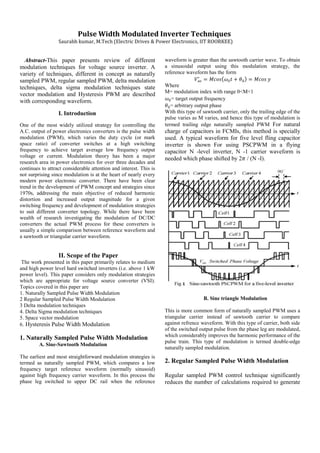
  • 1. Pulse Width Modulated Inverter Techniques Saurabh kumar, M.Tech (Electric Drives & Power Electronics, IIT ROORKEE) Abstract-This paper presents review of different modulation techniques for voltage source inverter. A variety of techniques, different in concept as naturally sampled PWM, regular sampled PWM, delta modulation techniques, delta sigma modulation techniques state vector modulation and Hysteresis PWM are described with corresponding waveform. I. Introduction One of the most widely utilized strategy for controlling the A.C. output of power electronics converters is the pulse width modulation (PWM), which varies the duty cycle (or mark space ratio) of converter switches at a high switching frequency to achieve target average low frequency output voltage or current. Modulation theory has been a major research area in power electronics for over three decades and continues to attract considerable attention and interest. This is not surprising since modulation is at the heart of nearly every modern power electronic converter. There have been clear trend in the development of PWM concept and strategies since 1970s, addressing the main objective of reduced harmonic distortion and increased output magnitude for a given switching frequency and development of modulation strategies to suit different converter topology. While there have been wealth of research investigating the modulation of DC/DC converters the actual PWM process for these converters is usually a simple comparison between reference waveform and a sawtooth or triangular carrier waveform. II. Scope of the Paper The work presented in this paper primarily relates to medium and high power level hard switched inverters (i.e. above 1 kW power level). This paper considers only modulation strategies which are appropriate for voltage source converter (VSI). Topics covered in this paper are 1. Naturally Sampled Pulse Width Modulation 2 Regular Sampled Pulse Width Modulation 3 Delta modulation techniques 4. Delta Sigma modulation techniques 5. Space vector modulation 6. Hysteresis Pulse Width Modulation 1. Naturally Sampled Pulse Width Modulation A. Sine-Sawtooth Modulation The earliest and most straightforward modulation strategies is termed as naturally sampled PWM, which compares a low frequency target reference waveform (normally sinusoid) against high frequency carrier waveform. In this process the phase leg switched to upper DC rail when the reference waveform is greater than the sawtooth carrier wave. To obtain a sinusoidal output using this modulation strategy, the reference waveform has the form Where M= modulation index with range 0<M<1 = target output frequency = arbitrary output phase With this type of sawtooth carrier, only the trailing edge of the pulse varies as M varies, and hence this type of modulation is termed trailing edge naturally sampled PWM For natural charge of capacitors in FCMIs, this method is specially used. A typical waveform for five level fling capacitor inverter is shown For using PSCPWM in a flying capacitor N -level inverter, N -1 carrier waveform is needed which phase shifted by 2 / (N -I). B. Sine triangle Modulation This is more common form of naturally sampled PWM uses a triangular carrier instead of sawtooth carrier to compare against refrence waveform. With this type of carrier, both side of the switched output pulse from the phase leg are modulated, which considerably improves the harmonic performance of the pulse train. This type of modulation is termed double-edge naturally sampled modulation. 2. Regular Sampled Pulse Width Modulation Regular sampled PWM control technique significantly reduces the number of calculations required to generate
  • 2. PWM control in real-time. It also greatly simplifies the microprocessor software implementation, thereby considerably reducing the on-line computing requirements, and thus allows significantly higher switching frequency PWM to be generated using microprocessor techniques. In these strategies the low frequency reference waveforms are sampled and then held constant during each carrier interval. These sampled values are compared against the triangular carrier waveform to control the switching process of each phase leg. The sampled reference waveform must change values at either the positive or positive/negative peaks of carrier waveform, depending on the sampling strategies. A typical practical implementation of regular sampled PWM is illustrated in Fig. 2. As shown in the Figure, the sinusoidal modulating wave a is sampled at regular intervals tl, r2 etc., and stored by a sample-and hold circuit to produce an amplitude modulated wave b. Comparison of b with the triangular carrier wave c produces the points of intersection TI, T2 defining the switching edges of the PWM pulses d. The implementation of Fig. 2 is representative of a typical analogue or discrete digital hardware implementation, as shown in the diagram in Fig. 3. An important feature of Fig. 3 is that the modulating frequency , carrier frequency , and sampling frequency , are in general, as shown, independent, and therefore any desired relationship between them can be defined. The simplest relationship is to set , and therefore to sample the modulating wave at the carrier frequency, as shown in Fig. 3. This result in only one sample being taken every carrier cycle and therefore the sampled modulating wave is kept constant throughout the carrier period resulting in each edge of the PWM pulse being modulated equally; commonly referred to as symmetric modulation, as illustrated in Figs. 2 and 4. Alternatively, fs = 2fc can be used such that two samples of the modulating wave are taken each carrier cycle. The first sample taken at the start of the carrier cycle is used to modulate the leading edge of the pulse and the second sample, taken at the middle of the carrier cycle, used to modulate the trailing edge, resulting in asymmetric modulation, as shown in Fig. 4. Since more samples of the modulating wave are used to produce asymmetric PWM, the harmonic spectrum is superior to that of symmetric PWM.
  • 3. 2. Delta Modulation (DM) Technique The delta modulation (DM) technique requires a very simple circuit implementation, provides a smooth transition between the PWM and single pulse modes of operation and offers constant volts per Hertz operation without the need of additional circuit complexity. Some of the key voltage waveforms associated with the delta modulation technique is illustrated in Fig. 5(a), (b). Fig. 5(c) shows their respective circuit implementation. In particular, Fig. 5(a) illustrates the method by which the DM switching function (Fig. 5(b)), applicable to the PWM inverter, is obtained. This method utilizes a sine reference waveform and a delta-shaped carrier waveform is allowed to "oscillate" within a defined "window" extending equally above and below the reference wave . The minimum "window" width and the maximum carrier slope determine the maximum switching frequency of the inverter switchers , Therefore, when setting values for these two parameters, care should be taken so that sufficient time is provided for the proper turn-on and turn-off of and . Fig. 5(b) shows the DM switching function which describes the operation of switching elements and . The subscript of the element that is gated at any instance is indicated by the sequence of ones and twos shown in Fig. 5(b). The temporal relation between the gating sequence of elements and the waveform of the DM switching function VI yields that the inverter phase voltage , and have the same waveforms. Fig. 5(c) depicts a circuit that is capable of producing the waveforms shown in Figs. 5(a) and 5(b). This circuit operates in the following manner. Sine reference wave is supplied to the input of the comparator while carrier wave VF is generated by the integrator as follows: whenever the output of exceed the upper or lower “window” boundaries (which are preset by the ratio), comparator A 1 reverses the polarity of at the input of . This action reverses the slope of VF at the output of , thus forcing to "oscillate" around the reference waveform at ripple frequency r. This forced oscillation ensures that the fundamental component of (i.e. ) and reference wave have the same amplitudes and that the dominant harmonics of and waveforms oscillate at frequencies close to the ripple frequency r. 3. Delta Sigma modulation techniques The delta-sigma modulator is effectively applied to a voltage source inverter system with PWM pattern generating scheme. The major feature of delta-sigma modulator is the inherent nature of spread spectrum characteristic in addition to simple configuration scheme. Besides, delta-sigma modulator can be considered as a sort of error amplifier. If the inverter circuit is taken into feedback loop as a quantizer, external DC voltage disturbances can be reduced in the output side of inverter. 4. Space vector modulation Multiphase motor drives are a very promising technology, especially for medium and high power ranges. As known, a multiphase motor drive cannot be analyzed using the space vector representation in a single d-q plane, but it is necessary to introduce multiple d-q planes. So far a general space vector modulation for multiphase inverters is not available due to the inherent
  • 4. difficulty of synthesizing more than one independent space vector simultaneously in different d-q planes The basic scheme of a three-phase inverter is shown in Fig. 6. The signals are switch commands of the three inverter branches, and can assume only the values 0 or 1. The inverter output pole voltages are Where is the dc-link voltage. The main problem is to control the load phase voltages and according to the requirements imposed by the application, e.g. vector control of ac machines. An elegant solution to this problem is the space vector representation of the load voltages, which describes the inverter pole voltages introducing a space vector and a zero sequence component as follows: (2) (3) Where the coefficients k=1,2,3) are defined as follows: (4) The space vector and the zero sequence components can be expressed as functions of s1, s2 and s3 by substituting (1) in (2) and (3). (5) (6) It is well-known that the load voltages depend only on the space vector of the pole voltages, whereas the inverter zero sequence component affects only the potential of the load neutral point. In other words, to control the load, it is sufficient to control the vector . SVM for Three-Phase Inverters The modulation problem consists in controlling the switch states such that the mean values of the inverter output voltages are equal to the desired values in any switching period Tp. There are eight (namely ) possible configurations for a three-phase inverter, depending on the states of the three switch commands s1, s2 and s3. Six configurations correspond to voltage vectors with non-null magnitudes. These vectors, usually referred to as active vectors, are represented in Fig. 2, where the configurations of each vector are also expressed in the form ( . Two configurations, i.e. and lead to voltage vectors with null magnitudes, usually referred to as zero vectors. The space vector modulation selects two activevectors and applies each of them to the load for a certain fraction of the switching period. Finally, the switching period is completed by applying the zero vectors. The active vectors and their duty-cycles are determined so that the mean value of the output voltage vector in the switching period is equal to the desired voltage vector. The best choice is given by the two vectors delimiting the sector in which the reference voltage vector lies. Since two consecutive vectors differ only for the state of one switch, this choice allows ordering the active and the zero vectors so as to minimize the number of switch commutations in a switching period. For example, if the desired voltage vector lies in sector 1, as shown in Fig. 7, the two adjacent voltage vectors are and , whose configurations (0,0,1) and (0,1,1) differ for only one bit. After the active vectors have been chosen, the requested voltage can be expressed as a combination of them as follows: (7) where and are the duty-cycles of and in the switching period.
  • 5. The explicit expressions of and can be easily calculated evaluating the following dot products: (8) (9) (10) (11) Once and have been calculated, the designer can still choose in which proportion the two zero vectors are used to fill the switching period. Fig. 8 shows the vector sequence corresponding to the example of Fig. 7. In the sequence of Fig. 3, the zero vectors are equally distributed in the switching period. 6. Hysteresis Pulse Width Modulation Hysteresis PWM refers to the technique where the output is allowed to oscillate within a predefined error band, called "hysteresis band". The switching instants in this case are generated from the vertices of the triangular wave shown in Fig. 9. Hysteresis PWM techniques does not require any information about the inverter load characteristics. As long as the reference signal is known and the inverter output voltage is not saturated, the inverter output will always follow the reference. However, the switching frequency of power devices is not fixed for this technique and will vary depending on the magnitude and frequency of the reference,. Therefore, switching losses for this techniques can be higher compared to other techniques. IV CONCLUSION In this term paper pulse width modulation inverter techniques has been presented. Through various modulation techniques a general hierarchical consensus appears to have emerged from this work which ranks space vector modulation techniques, regular sampled modulation and sine-triangle modulation strategies in decreasing order of merit based on harmonics performance V. REFRENCES [1] Lega, A.; Mengoni, M.; Serra, G.; Tani, A.; Zarri, L., "General theory of space vector modulation for five-phase inverters," Industrial Electronics, 2008. ISIE 2008. IEEE International Symposium on , vol., no., pp.237,244, June 30 2008-July 2 2008 [2] Holtz, J., "Pulsewidth modulation-a survey," Power Electronics Specialists Conference, 1992. PESC '92 Record., 23rd Annual IEEE , vol., no., pp.11,18 vol.1, 29 Jun-3 Jul 1992 [3] Bowes, S.R.; Lai, Y.S., "Investigation into optimising high switching frequency regular sampled PWM control for drives and static power converters," Electric Power Applications, IEE Proceedings - , vol.143, no.4, pp.281,293, Jul 1996 [4] Sanakhan, S.; Babaei, E.; Akbari, M.E., "Dynamic investigation of capacitors voltage of flying capacitor multilevel inverter based on sine-sawtooth PSCPWM," Power Electronics, Drive Systems and Technologies Conference (PEDSTC), 2013 4th , vol., no., pp.182,187, 13-14 Feb. 2013 [5] Zhenyu Yu; Mohammed, A.; Panahi, I., "A review of three PWM techniques," American Control Conference, 1997. Proceedings of the 1997 , vol.1, no., pp.257,261 vol.1, 4-6 Jun 1997 [6] Hirota, A.; Nagai, S.; Nakaoka, M., "A novel delta-sigma modulated DC-DC power converter operating under DC ripple voltage," Industrial Electronics Society, 1999. IECON '99 Proceedings. The 25th Annual Conference of the IEEE , vol.1, no., pp.180,184 vol.1, 1999 [7]Holmes,D.G. and Lipo , T.A. "Pulse Width Modulation for Power Converters:Principles and Practice "