Armature Reaction
•Als PPTX, PDF herunterladen•
39 gefällt mir•21,478 views

Armature Reaction in dc machines...........

Empfohlen
Weitere ähnliche Inhalte
Was ist angesagt?
Was ist angesagt? (20)
Andere mochten auch
Andere mochten auch (20)
Ähnlich wie Armature Reaction
Ähnlich wie Armature Reaction (20)
Mehr von Vishal Thakur
Kürzlich hochgeladen
Kürzlich hochgeladen (20)
Armature Reaction
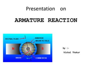
- 1. Presentation on ARMATURE REACTION by :- Vishal Thakur
- 2. What is Armature Reaction ? Armature Reaction in a d.c. machine is basically the effect of armature produced flux on the main flux or field flux .
- 3. Effects… • The armature reaction produces the following two undesirable effects: 1. It demagnetizes or weakens the main flux. 2. It cross-magnetizes or distorts the main flux.
- 4. Reduction in main flux per voltage reduces the generated voltage and torque whereas distortion of the main-field flux influences the limits of successful commutation in d.c. machines.
- 5. Explanation… • To understand this process let us first assume a 2- pole d.c. machine at no load . At that instant there is no armature current . So the flux due to mmf produced by field current in the machine at north pole of the magnet will flow towards the south pole of the magnet.
- 6. • The net / resultant flux of the system can be taken as a straight horizontal line OA and can be shown in phasor as :- • Also at that instant the Magnetic Neutral Axis (M.N.A) of the machine will concide with the Geometrical Neutral Axis (G.N.A) of the machine as the M.N.A is always perpendicular to the net flux.
- 7. • Now when the dc machine is loaded , current flows in armature windings . This armature current set up armature flux . With field windings unexcited , the flux can be shown as vertical lines across armature conductors . • The conductors on the left side of the M.N.A will have current flowing in inside direction whereas on right side of MNA , the current will flow in outside direction. The direction of the flux thus produced can be determined by using Maxwell‘s Right hand Screw rule.
- 8. • The resultant flux of the system is a straight vertical line OB and can be shown in phasor as :- • Note that the magnitude of OB will always be less than OA since the cause of armature flux is field flux and it is known to us that effect is always less than cause. Here armature flux is the effect and field flux is its cause.
- 9. • An examination to the above two phasors reveals that the path of armature flux is perpendicular to the main field flux. • In other words, the path of the armature flux crosses the path of the main field flux. This can be shown in phasor as :- • Thus the effect of armature flux on the main field flux is entirely ‘cross-magnetizing’ and it is for this reason that the flux produced by armature mmf is also called as cross-flux.
- 10. • When the current flows in both the armature and field windings, the resultant flux distribution is obtained by superimposing theses two fluxes. i.e.
- 11. • It is observed that the armature flux aids the main field flux at the lower end of the N-pole and at the upper end of the S-pole, therefore at these two poles, the armature flux strengthens the main field flux. • Likewise, the armature flux weakens the main field flux at Upper end of the N-pole and at lower end of the S-pole.
- 13. • Now, if there is no magnetic saturation, then the amount of strengthening and weakening of the main field flux are equal and the resultant flux per pole remains unaltered from its no load value. • Actually, the magnetic saturation does occurs and as a consequence, the strengthening effect is less as compared to the weakening effect and the resultant flux is decreased from its no-load value. This is called ‘Demagnetizing effect of armature reaction’
- 14. • So when the machine is run loaded , M.N.A will shift from G.N.A of the machine . • The resultant shift is completely dependent on the magnitude of armature current. • Thus, greater the value of armature current , greater is the shift of MNA from GNA .
- 15. • It may therefore be stated from the above that net effect of armature flux on the main field flux is:- 1. To distort the main field flux thereby causing non-uniform distribution of flux under the main poles. 2. To shift the MNA in the direction of the rotation for a generator and against the direction of rotation for a motor. 3. To reduce the main field flux from its no-load value due to magnetic saturation.
- 16. Methods to reduce Armature Reaction • There are various methods of reducing the armature reaction, some of them are:- 1. Compensate Windings 2. Interpoles or copoles
- 17. Compensating Windings • The compensating windings consist of a series of coils embedded in slots in the pole faces. • These coils are connected in series with the armature in such a way that the current in them flows in opposite direction to that flowing in armature conductors directly below the pole shoes.
- 18. • The series-connected compensating windings produce a magnetic field, which varies directly with armature current. • As the compensating windings are wound to produce a field that opposes the magnetic field of the armature, they tend to cancel the effects of the armature magnetic field.
- 20. Interpoles • Another way to reduce the effects of armature reaction is to place small auxiliary poles called "interpoles" between the main field poles. • Interpoles have a few turns of large wire and are connected in series with the armature.
- 21. • Interpoles are wound and placed so that each interpole has the same magnetic polarity as the main pole ahead of it, in the direction of rotation. • The field generated by the interpoles produces the same effect as the compensating winding. This field, in effect, cancels the armature reaction for all values of load current.