Role of CAN BUS in automotives
•Als PPT, PDF herunterladen•
0 gefällt mir•859 views

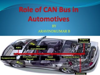
It gives the good explanation about the role of CAN BUS in modern day automotives

Empfohlen
Weitere ähnliche Inhalte
Was ist angesagt?
Was ist angesagt? (20)
Ähnlich wie Role of CAN BUS in automotives
Ähnlich wie Role of CAN BUS in automotives (20)
Mehr von Yuga Aravind Kumar
Mehr von Yuga Aravind Kumar (20)
Kürzlich hochgeladen
Kürzlich hochgeladen (20)
Role of CAN BUS in automotives
- 2. Distributed Systems in Vehicles CAN LIN MOST Byteflight D2B K-line FlexRay
- 3. Introduction to CANBUS CANBUS or CAN bus – Controller Area Network bus An automotive serial bus system developed to satisfy the following requirements: Network multiple microcontrollers with 1 pair of wires. Allow microcontrollers communicate with each other. High speed, real-time communication. Provide noise immunity in an electrically noisy environment. Low cost
- 4. Who uses CANBUS? Designed specifically for automotive applications Today - industrial automation / medical equipment 0% 10% 20% 30% 40% 50% 60% 70% 80% 90% 100% Automotive Medical / Industrial Markets CANBUS Market Distribution
- 5. CANBUS History First idea - The idea of CAN was first conceived by engineers at Robert Bosch Gmbh in Germany in the early 1980s. Early focus - develop a communication system between a number of ECUs (electronic control units). New standard - none of the communication protocols at that time met the specific requirements for speed and reliability so the engineers developed their own standard.
- 6. CANBUS Timeline 1983 : First CANBUS project at Bosch 1986 : CAN protocol introduced 1987 : First CAN controller chips sold 1991 : CAN 2.0A specification published 1992 : Mercedes-Benz used CAN network 1993 : ISO 11898 standard 1995 : ISO 11898 amendment Present : The majority of vehicles use CAN bus.
- 7. CANBUS and the OSI Model
- 8. Application Areas of Distributed Systems in Vehicles – Power Train Communicating units engine, brake, gear, ABS/ESP steering wheel position, steering booster light control, damper … High-speed and reliability are required running only when the ignition is on in future the technologies for X by wire will be applied Today standards CAN (high-speed) Byteflight Future: the FlexRay standard
- 9. Application Areas of Distributed Systems in Vehicles – Comfort Functions Communicating units seat position control, mirrors control, windows control air condition, vehicle top, tires pressure control, parking assistant wiper control, door control … Lower-speed is enough Low-power mode is required units wake-up by data transmission running also when ignition is off Today standards CAN (low-speed) LIN
- 10. Application Areas of Distributed Systems in Vehicles – Infotainment and Telematics Communicating units sound system, CD player, changer, tuner TV set, mobile phone, navigation inter-vehicle communication, traffic info reception … Different communication speeds low speed for control transfers high speed for user data transfers (audio, video) Low power mode required unit wake-up by data communication running if ignition is off Today standards CAN (low-speed) MOST
- 11. Application Areas of Distributed Systems in Vehicles – Diagnostics Communicating units all (use their native interface) … Different interfaces today often so called K-line with diagnostics protocols gateway unit often translates diagnostics protocols of particular ECUs in future the wireless diagnostics is expected using bluetooth ??? … security is the issue
- 12. CAN and ISO-OSI Model Physical layer transmission line parameters, signaling levels, transmission speed, … Link Layer = CAN medium access control frame coding and decoding addressing data security error states behavior
- 13. CAN and ISO-OSI Model Application layer defines the data content of link layers frames defines when (under which conditions) the frames are transmitted in automotive industry there are only company standards standards do exist for diagnostics Application protocols are defined e.g. in industrial automation field (CANopen) effort to use them in vehicles too
- 14. CAN and ISO-OSI Model Inter-layer communication each protocol layer adds some information that allows the layer protocols to provide the required service for the layer above P1 P1 P2 P2 P3 P3 data data data data layer L1 layer L2 layer L3 layer L1 layer L2 layer L3
- 15. CAN – Physical Layer Requirements The basic requirement for the physical layer is to provide so called wired OR functionality Two basic signaling levels recessive dominant available e.g. in fiber optics Vcc Vcc 1 2 3 Bus
- 16. CAN – Link Layer, MAC and LLC MAC – Medium Access Control provides the physical channel access for the units, prevents destructive collisions provides priority transmission implements the channel coding provides the data security by means of CRC check solves high error rate problem for particular nodes in network provides mechanism for acknowledgement of correctly received frames LLC – Logical Link Control allows filtering of received frames solves the overload condition
- 17. CAN – Communication Principle All nodes within the systems are equal (from the communication point of view) – peer to peer Frames, (sometimes called messages) are broadcasted into the network and received by all nodes simultaneously There is no node oriented addressing frame always starts with identifier, which must provide a unique frame content identification In case the frame is received correctly by receiving nodes, the acknowledge is sent to the transmitting node In case there is an error detected during the transmission, the error identification sequence is sent and frame has to be transmitted again
- 18. Message Oriented Transmission Protocol Each node – receiver & transmitter A sender of information transmits to all devices on the bus All nodes read message, then decide if it is relevant to them All nodes verify reception was error-free All nodes acknowledge reception
- 19. Message Format Each message has an ID, Data and overhead. Data –8 bytes max Overhead – start, end, CRC, ACK
- 20. CAN – Medium Access Control Any node can start transmitting only if the bus idle state is detected In case that more than one node start transmitting simultaneously there is no physical contention on the bus, as the dominant bit transmission „beats“ the recessive one Each node receives back the transmitted bit value if a node transmitting the recessive bit value receives back the dominant bus state, it stops transmitting immediately This method is called CSMA/CR Carrier Sense Multiple Access with Collision Resolution sometimes it is also less correctly called CSMA/CA (…Collision Avoidance)
- 21. CAN – Medium Access Control 3 nodes start transmitting simultaneously Start of Frame (SOF) bit is always dominant 11 bits of identifier follow identifier must be unique within the system
- 22. CAN – Frame Identifier Identifies the frame content It is not the sender nor the receiver address usually one node transmits frames with different identifiers each node receives frames with identifiers it is interested in Identifier must be unique within the system two different nodes are not allowed to transmit frame with the same identifier (because of arbitration) In case the information source redundancy is required, identifiers usually differ in low significant bit Identifier is transmitted from the most significant bit log. 0 is transmitted as a dominant state, log. 1 as a recessive the lower identifier value, the higher frame priority
- 23. CAN – Frame Format Current standard version is CAN 2.0 Bosch, 1990 it defines only the link layer protocol there are two parts (variants) A and B CAN2.0A is backward compatible with older CAN versions, it uses 11-bit identifier CAN2.0B defines two data frame types – standard and extended standard frame offers 11-bit identifier extended frame offers 29-bit identifier Accepted as ISO11898-1 standard next standard parts define the physical layer protocols too
- 24. CAN – Frame Format 4 frame types are defined data frame used for data transfer variable length (0 – 8 data bytes) remote request frame used to request the data frame with the same identifier it contains no data error frame consists of six consequent dominant or recessive bits it is transmitted to indicate the error overload frame the same format like the error frame nodes transmit it to delay the next data frame transmission
- 25. CAN 2.0A – Data Frame Format bus idle – recessive state SOF – start of frame arbitration field (identifier + RTR bit) control field (dedicated bits + data length) Both dedicated bits have a dominant value data (0 – 8 bytes) CRC (15-bit CRC, 1 recessive bit as a delimiter) acknowledge (1 bit acknowledge, 1 bit delimiter) end of frame (7 recessive bits) inter-frame space (3 recessive bits) frame identifier R T R data length 0 - 8 data bytes Control field CRC Bus idle CRC 15 bits E R C S O F Length: 1 11 1 1 41 0 - 64 15 1 1 1 7 end of frame A C K A C D 3 R 0 Arbitration field Data field R 1 Acknowledge inter-frame space
- 26. CAN 2.0B – Standard Data Frame Format In fact the same like CAN 2.0A frame format Only the formal difference bit r1 name changed to IDE (identifier extended) The IDE bit is always dominant in a standard data frame Arbitration field Data field S O F frame identifier 11 bits R T R Control field I D E R 0 data length Bus idle
- 27. CAN 2.0B – Extended Data Frame Format Allows higher number of frames in particular system RTR bit is replaced by SRR bit (substitute remote request) always recessive IDE bit is always recessive standard frame with the same first 11 bits of identifier has higher priority Following 18 identifier bits are used for arbitration among extended frames only CAN controllers provide either active or passive compatibility with CAN2.0B R 0 I D E S O F R 1 R T R S R R Data field R 0 I D E data length frame identifier 11 bits frame identifier 18 bits R 1 R T R S R R Arbitration field Control field Bus idle
- 28. CAN 2.0A – RTR Frame Format RTR bit is always recessive RTR frame identifier is the same like the data frame identifier which transmission is requested RTR frame has lower priority than the data frame with the same identifier do you know WHY ??? Data length is always 0 Similarly it exists an extended RTR frame format according to the CAN 2.0B frame identifier R T R data length Control field CRC Bus idle CRC 15 bits E R C S O F Length: 1 11 1 1 41 15 1 1 1 7 end of frame A C K A C D 3 R 0 Arbitration field R 1 Acknowledge field inter-frame space
- 29. CAN – Error Frame Format Error frame consists of six dominant or recessive bits it depends on error state of the node which transmits it It is transmitted by the node (-s) that detect (-s) any communication error it result in an immediate transmission stop and its later repetition this is all controlled by the controller (implemented in silicon), not by application software Error flag Superpozition of error flags Data frame or error delimiter or overload delimiter Error frame Error delimiter Inter-frame space or overload frame
- 30. CAN – Overload Frame Format Overload frame consists of six dominant bits Its transmission is requested by the receiver in order to delay the transmission of a next data frame indicate a detection of a dominant value in a last bit of the end of frame field or in first two bits of inter-frame space Its occurrence does not mean an error previous frame is not retransmitted Today controllers do not use it to delay the next transmission – they are fast enough Overload flag Superpozition of overload flags Overload frame Overload frame delimiter Inter-frame space or overload frame Data frame or error delimiter or overload delimiter
- 31. CAN – Error Detection Several simultaneously used mechanisms: Monitoring transmitter receives back the bus state and if it detects a different value, its behavior is: in case it detects a dominant bus state within the arbitration field while transmitting the recessive one, it stops transmitting in case it detects a recessive bus state within the arbitration field while transmitting the dominant one, or if it detects anywhere else (excluding the ACK bit) opposite bus state than that one it is currently transmitting, it sends the error frame CRC (Cyclic Redundancy Check) in case the locally evaluated CRC is different from the received one, the error frame is transmitted
- 32. CAN – Error Detection Bit stuffing transmitter transmits particular bits using NRZ (not return to zero) coding if there is a sequence of 5 consecutive bits of the same level, one bit of the opposite level is inserted during the reception an inverse process takes place, it means after five received bits of the same level the next bit must be of the opposite level (check) and it is known it is an inserted bit – it is thus removed
- 33. CAN – Bit Stuffing Error frame transmission violates bit stuffing rule all nodes thus detect the error it is thus ensured that the frame is received either by all nodes or by no node data consistency
- 34. CAN – Error Detection Frame format check some bits have predefined level CRC or ACK delimiters are always recessive end of frame field is whole recessive if there is a dominant bit detected, an error frame is sent data length field can contain value higher than 8 length of 8 is expected error frame is not sent Frame receive acknowledge by the dominant level in the ACK bit if there is no acknowledge, transmitting node sends an error frame data frame transmission is repeated
- 35. CAN – Node Error States One node encountering communication problems could block complete communication within the system it detects an error in each received frame and transmits an error frame it is necessary to limit this possibility There are two so called error counters in each CAN controller (and thus in each network node) one for errors during transmission, one during reception at the beginning they are reset if there is an error during transmission, transmission error counter value is increased, the same is tru for reception If the transmission or reception have passed without error, the respective value is decremented (up to zero) According to the error counters values particular node is in one of three error states
- 36. CAN – Node Error States Error active value of each of both error counters has to be lower than 128 in case the error is detected during the frame transmission or reception, an active error flag (6 consecutive dominant bits) is generated it breaks communication and all other nodes within the system detect error as well the number the respective error counter is increased (0, 1 or 8) depends on the error context, it means the situation and conditions of error detection if any of error counters reaches the value higher than 127, the respective node goes into the error passive state
- 37. CAN – Node Error States Error passive the value of at least one error counter is higher than 127 if the node detects communication error, it generates a passive error flag (6 consecutive recessive bits) if the error passive node is the only one who detects error (probably incorrectly), the communication is not broken and can be finished and acknowledged by other nodes in case of successful reception the respective counter is either decremented (if its value was lower than 128) or set between 119 and 127 (if its value was higher 127) if the values of both counters fall under 128, the node goes back to error active state if the value of transmission error counter gets over 255, the controller enters bus-off state
- 38. CAN – Node Error States Bus-off state transmission error counter value is higher than 255 reception error counter value has no influence on entering into the bus-off state bus-off node is completely disconnected from the network (logical not physical disconnect) it is not possible to transmit frames nor to influence the bus communication by any way (no ACK, error frame..) reception is possible (depends on implementation) from the point of view of other nodes the bus-off node disappears from the network (like switched off) to leave the bus-off state only the controller hardware or software reset is available then after the detection of 128 recessive 11-bit sequences the controller enters an error active state incorrect software implementation can make global problems in communication
- 39. CAN – Error States Servicing CAN controller Status register usually contains: Error warning flag set if any error counter reaches some limit usually 96 sometimes this limit can be preset controller can generate an interrupt service request application software (node firmware) may or may not service this event Error passive flag set by entering the error passive state interrupt service request possible Application software should také into account possible data inconsistency within the local node and the rest of a network Bus-off flag controller reinitialization is necessary
- 40. CAN – Persisting communication problems It always depends on the error type, direction of communication (reception, transmission) where it takes place as well as the physical layer protocol version e.g. tolerance to some shorts Fatal errors (e.g. Short connection of both CAN lines to ground) always finishes in bus-off state only in case the node tries to transmits The node which is alone in the network (or disconnected by cable interrupt), enters after 16 unacknowledged frame transmissions into an error passive state If the software service of error states is not correctly implemented, serious communication problems may occur Under the standard conditions all nodes within the system are in the error active state and there are no error frames generated
- 41. CAN – Physical Layer Standards CAN standard (Bosch) defines the link layer protocol only It is also standardized by ISO as ISO11898-1 Physical layers are defined in standards ISO11898-2 high-speed CAN up to 1 Mbit/s and ISO11898-3 low-speed CAN up to 125 kbit/s particular fault tolerance Both these physical standards are widely used in today vehicles For trucks there are othe standards available with higher degree of immunity They are all defined as SAE standards too
- 42. CAN – ISO11898-2 Physical Layer Bus structure with terminators Line impedance of 120 ohm Communication speed up to 1 Mbit/s Differential signaling (logical level defined by voltage difference) CAN_H and CAN_L lines
- 43. CAN – ISO11898-2 Physical Layer The recessive level is provided by terminators and „wake“ voltage sources in transceivers CAN_H – CAN_L difference is near 0 The dominant state is driven by the transceiver CAN_H – CAN_L difference is about 2 volts
- 44. CAN – ISO11898-2 Physical Layer The transceiver contains the temperature, short circuit and ESD protection Low load in power off state Some offer low power states
- 45. CAN – ISO11898-3 Physical Layer Bus structure Sleep mode with remote wake-up by CAN communication Communication speed up to 125 kbit/s Differential signaling
- 46. CAN – ISO11898-3 Physical Layer Particular fault tolerance, transceiver enters so called single wire mode CAN_H or CAN_L wire broken short connection of CAN_H or CAN_L to ground short connection of CAN_H or CAN_L to +5V short connection of CAN_H or CAN_L to +12V short connection of CAN_H to CAN_L Single wire mode is indicated by the transceiver output after the fault is removed transceiver automatically enters standard two wire mode
- 47. CAN – ISO11898-3 Physical Layer RTH and RTL resistors provide termination their values depend on number of nodes in system Transceiver supports node wake-up when the CAN activity is examined, or by he local signal Sleep mode is controlled by the local microprocessor if the whole bus is in sleep (low power) mode, CAN_H voltage is near 0 and CAN_L voltage is near the battery one
- 48. CAN – Immunity to External Disturbances Information is transferred by the voltage difference if both wires are close the induced disturbance is the same, difference stays the same the absolute value of the induced disturbance can be further decrease with utilization of twisted pair wire
- 49. CAN – Transmission Timing všechny uzly v síti musí mít nastavenu shodnou nominální přenosovou rychlost skutečné rychlosti se mírně liší (tolerance oscilátorů) vzhledem k faktu, že v průběhu arbitráže může vysílat více uzlů najednou, že arbitráž probíhá bit po bitu a že šíření informace z jednoho uzlu do druhého je zatíženo zpožděním (budič – vedení – přijímač), je třeba: kompenzace statických zpoždění průběžné synchronizace kvůli odchylkám oscilátorů
- 50. THANK YOU