SlideShare ist ein Scribd-Unternehmen logo
1 von 5
Downloaden Sie, um offline zu lesen
Real-Time Football Cup 2011
                              Project report - Team 1
       Hoo Chin Hau, Lee Hui Hui Evon, Lee Wang Wei, Lo Yat Piu, Ng Zhong Qin, Teo Sing Ying Alex


                      I. I NTRODUCTION                              C. Artificial Intelligence Co-processor
  The objective of this project is to develop a soccer system.
The project involves 3 FPGAs, 2 of them are the Spartan 3E             An AI co-processor was implemented in order to offload
board, while the third is a Spartan 6. Of the two Spartan 3Es,      computationally intensive calculations used in the client AI
one plays the role of the server, while the other is the client.    system to custom hardware. It is implemented as a Xilinx
The Spartan 6 acts as a High Definition display controller, as       EDK custom IP project that is designed to be imported into
an additional feature.                                              the client XPS project. The AI co-processor provides registers
                                                                    for the Microblaze processor to write to and read from through
      II. H ARDWARE D ESIGN AND I MPLEMENTATION                     the slave PLB interface of the AI co-processor. The Microblaze
                                                                    processor writes the current state data (the packets received)
A. Server
                                                                    into input registers for the co-processor to work on, and the
   The server is configured with 2 Microblaze cores, each with       co-processor writes the results into result registers for the
2KB instruction cache and 8KB data cache. Microblaze 0              Microblaze processor to read from. A configuration register
(MB0) is designated to be the graphics core, and is hence con-      allows the processor to issue instructions. In order to indicate
nected to a DMA controller. The DMA controller essentially          that the co-processor has completed its calculations and the
copies bitmap data into the TFT frame buffer without CPU            result register is ready to be read, an interrupt is issued.
intervention, thereby allowing the processor to perform other          Five functions are determined to be computationally inten-
tasks in parallel. In addition, the DMA controller attempts         sive and was implemented in custom hardware.
to optimize the speed of the data transfer by initiating burst
transactions instead of single beat transfers whenever possible.      •   In Range - The function determines whether a player is
Therefore, DMA can draw a complete screen much faster than                in kicking range of the ball so that the player can execute
the Microblaze. Unfortunately, data transfer using DMA is still           a kick command
not fast enough to meet the strict deadline required to refresh       •   Seek - The function calculates the optimal speed and
the screen at 60 Hz during runtime, and thus it was used only             direction of the player given the player and ball state
for pre-loading of full screen images.                                    information so that the player will reach the ball in the
   The second Microblaze (MB1) is tasked to handle commu-                 shortest time possible. The algorithm takes into account
nications and physics calculations. Information about game                ball bouncing as well to predict future ball positions.
state, player and ball positions are relayed to MB0 through           •   Best Supporting Position - The function calculates the
a hardware mailbox. In addition, the same information is                  best supporting position where a player should move/pass
also relayed to a Spartan 6 FPGA for high definition display,              the ball to. Scores are assigned to various points of the
through an ethernet connection.                                           field in which goal scoring potential, passing potential
   Information on current game state, ball and player positions           and optimal distance from the ball are considered. The
are also relayed to the client boards via RS232 connections at            position on the field with the highest score is deemed to
115200 baud rate.                                                         be the best supporting position.
                                                                      •   Move To Target - The function calculates the optimal
B. Client                                                                 speed and direction of the player given a target position
   A single Microblaze drives the Client board. It is responsible         so that the player approaches the target in the shortest
for communicating with the server, as well as implementing                time possible.
the strategy after considering the position of the ball and           •   Check Goal - The function determines whether a goal
players. Dip switch and push buttons are used to indicate the             can be scored based on the position of the ball, taking
start of the game and the side the team is playing on. Moreover,          into account whether there are players blocking the goal
a hardware co-processor is developed to aid in the complex                scoring shot and returns the best direction for goal
calculations required for the strategy implemented.                       scoring.
D. High Definition Display                                             Running with a lower priority is the simulation thread.
                                                                   As calculations may be rather complex depending on the
   An advanced version of the field display is created using
                                                                   situation, there may be times where it may fail to meet the
the Atlys Spartan 6 board which has an HDMI output port.
                                                                   deadlines. However, as the thread runs asynchronously to the
Since the VGA output provided by the xps tft controller uses
                                                                   communications thread, a missed deadline is not catastrophic,
a signaling protocol that is very different from the Transition
                                                                   and the correct data will be available on the next cycle.
Minimized Differential Signaling (TMDS) used by HDMI, a
custom hardware core is created to utilize the HDMI port              2) Interrupts: Timer interrupts are triggered 25 times per
on the Spartan 6 board. The hardware core is based on the          second. Semaphores are posted with each interrupt, thus
reference design files that came with Xilinxs Application           ensuring the communication and simulation threads run at 25
Note 495 (XAPP495) which implements the required logic to          Hz.
serialize RGB data using the advanced IO logic and clocking           UART interrupts are triggered when a receive or send is
resources on the Spartan 6 board. However, Xilinxs design          complete. Upon receiving incoming data, a semaphore will be
procedurally generates a SMPTE color bars image instead of         posted by the receive ISR, allowing the communications thread
reading RGB data from a frame buffer, which is inadequate          to immediately copy data from the UART receive buffer into
to render a dynamically changing football field. Therefore,         a software circular buffer. The circular buffer is ideal in this
a controller is coded in Verilog to utilize the Video Frame        case as we are only interested in the most recent data. We have
Buffer Controller (VFBC) Personality Interface Module (PIM)        also tried using the system message queue but abandoned that
of the multi-port memory controller. VFBC allows 2D video          due to performance reasons.
data to be read from a frame buffer using a simple command            The send interrupt is used for flow control, to ensure that
based interface. During the horizontal blanking period, a read     data is written into the send buffer only when the previous
command is sent to the VFBC to allow video data to be fetched      entries are sent out. Every time a timer interrupt is triggered, a
from the DDR RAM. The data is then pushed into a FIFO              semaphore is posted and the communications thread will pack
before being popped during the active video period. The FIFO       the data to be sent into the send buffer. It will then check a
is crucial in bridging between the different clock domains of      flag to ensure that the previous batch of data is already sent
the memory controller and the HDMI controller. Due to the          before it calls the send command. When send is complete, the
limited DDR bandwidth and speed of the IO logic of the board,      designated interrupt service routine is called and the flag bit
a 720p HDMI output was designed instead of 1080p.                  is reset to indicate that it is clear for the next batch of data to
   The controller has 2 user accessible registers which are the    be sent.
frame buffer address register and the stride register. The first       The use of interrupts for communications is crucial in
register tells the controller where to fetch video data from       ensuring that data is read off the receive buffers of the UART
while the second register indicates the number of bytes to in-     as soon as possible. This is because the buffers are only 16
crement after fetching one line of video data. The combination     entries deep, and will overflow in just 1.11 ms at 115200 baud
of the two registers allows for interesting hardware accelerated   rate. Should polling be used, context switching would have to
effects such as panning of the screen in such a way that the       be done every 1ms, which is not practical given the overhead
ball is always in the center.                                      involved.
                                                                      3) Synchronization: The communication and simulation has
        III. S OFTWARE I MPLEMENTATION D ETAILS                    access to the shared game state by locking access to the shared
                                                                   memory region using a mutex lock. Due to the higher priority
A. Server                                                          level of the communications thread, it will have higher priority
   Microblaze 1 on the server runs two main threads, namely        on each 25Hz cycle to receive and send the data before the
communication and simulation. In addition, 3 interrupt service     simulation thread can access the data, ensuring that the actions
routines are setup to handle interrupts from the hardware timer,   are processed as soon as the data is received. The simulation
as well as the UART hardware.                                      thread also tries to reduce the time it locks access to the shared
   1) Priority Levels: The most important constraint for Mi-       memory region by copying data in and out to its own data
croblaze 1 is to send and receive updates to and from clients at   structure and unlocking access to this shared resource.
25 Hz. This thread also handles the passing of the game state         4) Graphics: Microblaze 0 runs 2 threads, one to read data
to the other Microblaze processor via a hardware Mailbox           from a hardware mutex, and the second to render the graphics.
to draw the game on the screen. To accomplish this, we             Priority scheduling is implemented.
assigned the communication thread with the higher priority,           Data is received from Microblaze 1 through a 512 byte
thus ensuring that no other threads can preempt it while it is     deep hardware mailbox at 25 Hz, with each packet containing
running. As this thread is event driven, it waits on semaphores    information such as ball and player coordinates, as well as the
when idle, thus preventing it from starving the simulation         state of the game. The reading thread has higher priority, and
thread.                                                            waits on a semaphore triggered by the mailbox interrupt.
In order to achieve smooth graphical transitions, double-       cations thread. After performing calculations, it converts the
buffering is implemented. A region is allocated in the DDR         final values into fixed point and writes back to the shared
memory to be used as video memory frame buffers. The               game state. As mentioned earlier, all access to shared memory
region is large enough for three frames, one for each alternate    locations are protected by mutex locks, thus preventing data
frame, and one as a reference. Essentially the graphics thread     corruption due to simultaneous access.
will draw onto a frame buffer which is not displayed. Upon
completion, the thread waits for a v-sync interrupt, which posts   B. Client
a semaphore, signaling the precise moment to switch to the            The client runs two threads. The first thread handles the
newly drawn frame buffer. Switching is done by changing            receiving of data from the server board while the second
the frame pointer of the controller to the new region in the       thread processes the information and lets the AI implement its
DDR memory. The thread will then perform the draw onto             strategy before sending it back to the server. The receive thread
the undisplayed buffer, and the cycle repeats itself again. As     waits for a semaphore from the receive interrupt handler.
the v-sync interrupts occur at 60 Hz, it is important to ensure    Once posted, the receive thread will run and pass the data
that the drawing process is performed within a 16.8ms time         to a global variable which has a defined structure. The AI
frame.                                                             thread then waits for a semaphore posted by the timer interrupt
   As the rendering thread runs at a higher frequency than the     and accesses the same global variable. Similar to the server,
reading thread, calculations have to be performed to determine     mutex locks are implemented to prevent data corruption due
the coordinates or objects in between each key frame. Various      to simultaneous access of a shared memory location.
optimizations are performed to ensure the drawing can be
done fast enough. Firstly, instead of erasing the entire ball
and player regions each time the screen is refreshed, the
intersection between the old and the new region is not erased
because it will be overwritten by the new data anyway. Erasing
in this context means to replace a pixel in the frame buffer
with the corresponding original pixel color in the reference
frame buffer. In addition, the C program is built with -O3
optimization flag enabled.
   5) High Definition Graphics: The game state is sent from
the Spartan 3E board to the Spartan 6 board via Ethernet at 25
Hz before being rendered with the same technique mentioned                            (a) Global Finite State Machine
above. However, in order to keep up with the frame rate
at a much higher resolution, further optimization is needed.
Firstly, the data and code section (except the bitmaps and
frame buffers) are placed in the local memory to eliminate
the bottleneck of fetching data from DDR RAM. Moreover,
coordinate interpolation calculations are performed as integers
instead of floating points because the latter take more clock
cycles and are not pipelined. To ensure that accuracy is
maintained when performing integer arithmetic, the remainder
of a integer operation is stored and the quotient is incremented
accordingly when the remainder is more than or equal to the
divisor.
   6) Physics and rules check: Physics calculations and rules                         (b) Player Finite State Machine
check are performed on a separate thread on Microblaze 1,                         Fig. 1.   Strategies Finite State Machine
with a lower priority than the communications thread. This
is done to ensure that the communications thread will not be          1) Strategy: There are three states in the global FSM,
pre-empted by the calculations thread, as the calculations may     mainly Attacking, Defending and Passing (See Fig 1a). Player
get complex depending on the situation.                            roles depend on the global state, as can be seen in Fig 1b.
   The calculations thread maintains its own set of object            In defending state, a player closest to the ball will be
coordinates and other attributes in floating point for finer         assigned to chase for the ball, while the rest of the team will
granularity. Each calculation cycle is triggered by a 25 Hz        mark opponents. Once the chaser is within range of the ball,
timer interrupt. At the start of each cycle, the thread updates    his state will turn into possess, and the global game state will
object attributes with information received by the communi-        go into Attacking.
Fig. 3.   Screenshot of Java Simulator
                Fig. 2.   Java simulator block diagram

                                                                      •  Set the initial positions of the players
   In Attacking mode, a Best Support Position (BSP) will be           •  Control player movements and kicks
calculated every cycle. With the help of the hardware co-              • Monitor the server output data by receiving and decoding
processor, the algorithm takes into consideration the position           the packets using the protocol specifications defined in the
of the ball as well as all player positions. The closest player          module wiki page
to the BSP will be assigned the role of Supporter, and will            • Monitor the rate of server to player packets by displaying
have to move to the BSP as fast as possible. Meanwhile, the              the following parameters:
Possessor also tries to dribble to the BSP, while other players        • Total packets sent
maintain their roles as Markers.                                       • Number of packets sent in the single second
   Once the Supporter is within range of the BSP, the game             • Average rate of sending packets (packets per second)
state goes into Passing mode, where the Possessor kicks the            • Refresh Rate ( packets per second/11)
ball in the direction of the BSP. In this state, the Supporter         • Stores the output log in a text file with the values stored
chases the ball, while other players maintain their Marker               as hex string
roles. The Possessor will maintain its heading and speed, as a         The program itself incorporates elements of a real-time
backup in case the pass is not successful. A countdown is also      system (Fig 2), and enabled us to perform simulation of the
initialized at the start of the state, and should the Supporter     game without the need for a client board, hence allowing the
fail to get in range of the ball before the countdown runs out,     team develop the server and client in parallel. This values
we assume that the pass has failed and the global state returns     shown in the screen-shot (See Fig 3) indicates that the hex
to Defending mode.                                                  values sent out by our server are correct. As illustrated, the
   At all points in time, the Possessor will attempt to shoot at    refresh rate of our server is indeed 25Hz.
the goal should it be in range and has clear line-of sight. This
criteria is also calculated with the help of the co-processor.      B. Python simulation for AI co-processor
   2) Communication with co-processor: Driver functions are            A python program is written to assist in the debugging of the
written for the co-processor so that the client can commu-          BSP calculation. The program displays visually the positions
nicate with the co-processor. The functions basically write         on the field that is possible for the ball to be passed to and
the received packets into the input registers, write the correct    determines whether a goal scoring opportunity is available. An
instruction word into the configuration register and unpack          example of the visualization can be seen below:
the result from the result register. To run a certain function on      In Fig 4, the blue dots represent positions that a pass can be
the co-processor, one calls the execution function, and waits       made, and the pink lines indicate that goal shots are possible
for the completion interrupt to occur using a semaphore. The        from that position. Using this visualization, one can determine
unpack function is then called to obtain the results from the       whether the calculated BSP in the co-processor is correct.
result register.                                                       As can be seen in the summary report, the co-processor
                                                                    meets the timing constraints of the Microblaze clock (< 20ns
              IV. T ESTING AND V ERIFICATION
                                                                    minimum period). Approximately 109120 clock cycles are
A. Java simulator                                                   required in the worse case scenario for the most complex
  In order to be sure that the server met the requirements          operation (BSP calculation), which would result in a delay
specified, a separate program was written to process the output      of roughly 2ms. This is still way faster than if it were
data on a PC. Features incorporated in the program include the      implemented on the Microblaze.
ability to:
VI. L ESSONS L EARNT
                                                                            One major mistake we made was the failure to test the sys-
                                                                         tem under full load. During the testing of the communication
                                                                         threads, we did not send data at the full rate specified, and
                                                                         hence did not foresee the problem of data-loss due to buffer
                                                                         overflow. The issue was discovered only at a much later date,
                                                                         leaving us with hardly any time left for debugging.
                                                                            Being a crucial part of the system, the lack of a stable
                                                                         communication also held back the debugging of the AI.
                                                                         Despite the ability of the hardware co-processor, the software
                                                                         strategy implemented was primitive and untested, which was
                                                                         a huge disappointment.
                   Fig. 4.   BSP Visualization in Python                    In general, we placed too much focus on developing extra
                                                                         features, most notably the high definition display. This left us
                                                                         with little time and manpower to ensure that basic require-
  Number   of   Slices:                3372   out of       14752   22%
  Number   of   Slice Flip Flops:      2053   out of       29504    6%
                                                                         ments are fulfilled.
  Number   of   4 input LUTs:          6348   out of       29504   21%
  Number   of   IOs:                    138                                                   VII. C ONCLUSION
  Number   of   bonded IOBs:            138   out of         250   55%
  Number   of   MULT18X18SIOs:           29   out of          36   80%      Despite the setbacks faced, we have gained invaluable
  Number   of   GCLKs:                    1   out of          24    4%   knowledge on real-time operating systems from this project.
  Minimum   period: 17.247ns (Maximum Frequency: 57.981MHz)              Not only do we learnt to optimize the code to meet stringent
  Minimum   input arrival time before clock: 13.248ns                    deadlines, we have also learnt how to configure the hardware
  Maximum   output required time after clock: 10.152ns
  Maximum   combinational path delay: 17.399ns}                          to deliver maximum performance. This includes the use of
                                                                         instruction and data-caches, as well as the hardware co-
                  V. P OSSIBLE I MPROVEMENTS                             processor and custom controller for high definition display.
A. Communication issues                                                  We have also realized the difficulties in debugging a real-
   The standard protocol assumes that not a single byte of data          time system, and the importance of rigorous tests to ensure
is lost throughout the entire match, which is a dangerous as-            reliability and robustness of the system.
sumption to make. In our experience, a single byte loss would               In terms of project management, we have learnt the impor-
result in corruption to all subsequent data received, and the            tance of including buffer periods in our development schedule,
only resolution would be to restart the entire match. Such an            in case of unforeseen technical complexities. It is also more
implementation would be unacceptable for any firm real-time               important to meet the basic requirements flawlessly than
systems, as it lacks robustness and error-detection/recovery.            having extra features.
To make things worse, Xilinx has published that the UartLite
serial controller has a 8% error rate, which increases with
increasing baud-rate used.
   Hence we propose to improve the communications protocol,
with the addition of sentinel flags to the beginning and end
of each update packet. This would at least provide a way for
client/servers to discover and recover from data loss.
   The most common cause of data loss is due to buffer
overflow on the receive buffers. While we have already imple-
mented interrupt service routines to discover incoming data,
as well as having the receive thread running at top-priority,
the problem can still occur. This issue has been identified to
be caused by slow execution of the communication thread, as
it code is placed in the DDR section of the memory. As DDR
arbitration is still based on a Round-Robin algorithm, the rate
at which the thread can execute is variable. We have since
learnt to enable a larger instruction cache on the Microblaze
1 of the server, as well as the client Microblaze, and the issue
has been resolved. Unfortunately, the realization came after
the project presentation, which is a step too late.

Weitere ähnliche Inhalte

Was ist angesagt?

eMMC Embedded Multimedia Card overview
eMMC Embedded Multimedia Card overvieweMMC Embedded Multimedia Card overview
eMMC Embedded Multimedia Card overviewVijayGESYS
 
ARM Processor architecture
ARM Processor  architectureARM Processor  architecture
ARM Processor architecturerajkciitr
 
ARM Cortex-M3 Training
ARM Cortex-M3 TrainingARM Cortex-M3 Training
ARM Cortex-M3 TrainingRaghav Nayak
 
Unit3 pipelining io organization
Unit3 pipelining  io organizationUnit3 pipelining  io organization
Unit3 pipelining io organizationSwathi Veeradhi
 
Direct Memory Access & Interrrupts
Direct Memory Access & InterrruptsDirect Memory Access & Interrrupts
Direct Memory Access & InterrruptsSharmilaChidaravalli
 
Direct Memory Access
Direct Memory AccessDirect Memory Access
Direct Memory AccessTuqa Rmahi
 
Architectural support for High Level Language
Architectural support for High Level LanguageArchitectural support for High Level Language
Architectural support for High Level LanguageSudhanshu Janwadkar
 
8257 DMA Controller
8257 DMA Controller8257 DMA Controller
8257 DMA ControllerShivamSood22
 
Direct memory access
Direct memory accessDirect memory access
Direct memory accessshubham kuwar
 
Question paper with solution the 8051 microcontroller based embedded systems...
Question paper with solution  the 8051 microcontroller based embedded systems...Question paper with solution  the 8051 microcontroller based embedded systems...
Question paper with solution the 8051 microcontroller based embedded systems...manishpatel_79
 
Topic 5 Digital Technique basic computer structure
Topic 5 Digital Technique basic computer structureTopic 5 Digital Technique basic computer structure
Topic 5 Digital Technique basic computer structureBai Haqi
 
VTU 4TH SEM CSE COMPUTER ORGANIZATION SOLVED PAPERS OF JUNE-2013 JUNE-2014 & ...
VTU 4TH SEM CSE COMPUTER ORGANIZATION SOLVED PAPERS OF JUNE-2013 JUNE-2014 & ...VTU 4TH SEM CSE COMPUTER ORGANIZATION SOLVED PAPERS OF JUNE-2013 JUNE-2014 & ...
VTU 4TH SEM CSE COMPUTER ORGANIZATION SOLVED PAPERS OF JUNE-2013 JUNE-2014 & ...vtunotesbysree
 

Was ist angesagt? (19)

DMA operation
DMA operationDMA operation
DMA operation
 
eMMC Embedded Multimedia Card overview
eMMC Embedded Multimedia Card overvieweMMC Embedded Multimedia Card overview
eMMC Embedded Multimedia Card overview
 
ARM Processor architecture
ARM Processor  architectureARM Processor  architecture
ARM Processor architecture
 
Introduction to Blackfin BF532 DSP
Introduction to Blackfin BF532 DSPIntroduction to Blackfin BF532 DSP
Introduction to Blackfin BF532 DSP
 
ARM Cortex-M3 Training
ARM Cortex-M3 TrainingARM Cortex-M3 Training
ARM Cortex-M3 Training
 
Unit3 pipelining io organization
Unit3 pipelining  io organizationUnit3 pipelining  io organization
Unit3 pipelining io organization
 
Bc0040
Bc0040Bc0040
Bc0040
 
Dvbshop
DvbshopDvbshop
Dvbshop
 
Direct Memory Access & Interrrupts
Direct Memory Access & InterrruptsDirect Memory Access & Interrrupts
Direct Memory Access & Interrrupts
 
Direct Memory Access
Direct Memory AccessDirect Memory Access
Direct Memory Access
 
TMS320C5x
TMS320C5xTMS320C5x
TMS320C5x
 
Architectural support for High Level Language
Architectural support for High Level LanguageArchitectural support for High Level Language
Architectural support for High Level Language
 
8257 DMA Controller
8257 DMA Controller8257 DMA Controller
8257 DMA Controller
 
Direct memory access
Direct memory accessDirect memory access
Direct memory access
 
Question paper with solution the 8051 microcontroller based embedded systems...
Question paper with solution  the 8051 microcontroller based embedded systems...Question paper with solution  the 8051 microcontroller based embedded systems...
Question paper with solution the 8051 microcontroller based embedded systems...
 
Topic 5 Digital Technique basic computer structure
Topic 5 Digital Technique basic computer structureTopic 5 Digital Technique basic computer structure
Topic 5 Digital Technique basic computer structure
 
Processors selection
Processors selectionProcessors selection
Processors selection
 
Choosing the right processor
Choosing the right processorChoosing the right processor
Choosing the right processor
 
VTU 4TH SEM CSE COMPUTER ORGANIZATION SOLVED PAPERS OF JUNE-2013 JUNE-2014 & ...
VTU 4TH SEM CSE COMPUTER ORGANIZATION SOLVED PAPERS OF JUNE-2013 JUNE-2014 & ...VTU 4TH SEM CSE COMPUTER ORGANIZATION SOLVED PAPERS OF JUNE-2013 JUNE-2014 & ...
VTU 4TH SEM CSE COMPUTER ORGANIZATION SOLVED PAPERS OF JUNE-2013 JUNE-2014 & ...
 

Andere mochten auch

Extreme Apps
Extreme AppsExtreme Apps
Extreme Appswebuiltit
 
Νέοι δημοσιογράφοι για το περιβάλλον, Δημοσιογραφική έρευνα και Δημοσιογραφικ...
Νέοι δημοσιογράφοι για το περιβάλλον, Δημοσιογραφική έρευνα και Δημοσιογραφικ...Νέοι δημοσιογράφοι για το περιβάλλον, Δημοσιογραφική έρευνα και Δημοσιογραφικ...
Νέοι δημοσιογράφοι για το περιβάλλον, Δημοσιογραφική έρευνα και Δημοσιογραφικ...peri mixou
 
X-mas promo 2012 pcshop.bg & stemo
X-mas promo 2012 pcshop.bg & stemoX-mas promo 2012 pcshop.bg & stemo
X-mas promo 2012 pcshop.bg & stemoVladimir Alexiev
 
20 marketing trend 2011
20 marketing trend 201120 marketing trend 2011
20 marketing trend 2011HIPO_Training
 
Immunopharmacology
ImmunopharmacologyImmunopharmacology
ImmunopharmacologyManish Kumar
 
9 customer complaint management
9 customer complaint management9 customer complaint management
9 customer complaint managementHIPO_Training
 
Smartphones and Technology
Smartphones and TechnologySmartphones and Technology
Smartphones and TechnologyPavan Belagatti
 
Arangkada Philippines forum January 26, 2012
Arangkada Philippines forum January 26, 2012Arangkada Philippines forum January 26, 2012
Arangkada Philippines forum January 26, 2012Arangkada Philippines
 
Social Media Marketing
Social Media MarketingSocial Media Marketing
Social Media MarketingClayton Kraby
 
日本搜尋器排名提升, 東京網頁改革
日本搜尋器排名提升, 東京網頁改革日本搜尋器排名提升, 東京網頁改革
日本搜尋器排名提升, 東京網頁改革www.MedreamLIVE.com
 
FYP%3A+Peer-to-Peer+Communications+Framework+on+Android+Platform
FYP%3A+Peer-to-Peer+Communications+Framework+on+Android+PlatformFYP%3A+Peer-to-Peer+Communications+Framework+on+Android+Platform
FYP%3A+Peer-to-Peer+Communications+Framework+on+Android+Platformwebuiltit
 
FYP%3A+Peer-to-Peer+Communications+Framework+on+Android+Platform
FYP%3A+Peer-to-Peer+Communications+Framework+on+Android+PlatformFYP%3A+Peer-to-Peer+Communications+Framework+on+Android+Platform
FYP%3A+Peer-to-Peer+Communications+Framework+on+Android+Platformwebuiltit
 
Immunopharmacology
ImmunopharmacologyImmunopharmacology
ImmunopharmacologyManish Kumar
 
businessmodelgeneration3
businessmodelgeneration3businessmodelgeneration3
businessmodelgeneration3Yeounjoon Kim
 
Pivotal Seminar PRESENTATION
Pivotal Seminar PRESENTATIONPivotal Seminar PRESENTATION
Pivotal Seminar PRESENTATIONKostas Kon
 
How VC/PE firms value businesses
How VC/PE firms value businessesHow VC/PE firms value businesses
How VC/PE firms value businessesKaustubh Kokane
 
ΜΑΥΡΕΣ ΤΡΥΠΕΣ
ΜΑΥΡΕΣ ΤΡΥΠΕΣΜΑΥΡΕΣ ΤΡΥΠΕΣ
ΜΑΥΡΕΣ ΤΡΥΠΕΣKostas Kon
 
Un año nuevo...J_M_R.
Un año nuevo...J_M_R.Un año nuevo...J_M_R.
Un año nuevo...J_M_R.Jose Martinez
 

Andere mochten auch (20)

Etiqueta y Protocolo - SENA Regional Distrito Capital - Juegos Mundiales Cali
Etiqueta y Protocolo - SENA Regional Distrito Capital - Juegos Mundiales CaliEtiqueta y Protocolo - SENA Regional Distrito Capital - Juegos Mundiales Cali
Etiqueta y Protocolo - SENA Regional Distrito Capital - Juegos Mundiales Cali
 
Extreme Apps
Extreme AppsExtreme Apps
Extreme Apps
 
Νέοι δημοσιογράφοι για το περιβάλλον, Δημοσιογραφική έρευνα και Δημοσιογραφικ...
Νέοι δημοσιογράφοι για το περιβάλλον, Δημοσιογραφική έρευνα και Δημοσιογραφικ...Νέοι δημοσιογράφοι για το περιβάλλον, Δημοσιογραφική έρευνα και Δημοσιογραφικ...
Νέοι δημοσιογράφοι για το περιβάλλον, Δημοσιογραφική έρευνα και Δημοσιογραφικ...
 
X-mas promo 2012 pcshop.bg & stemo
X-mas promo 2012 pcshop.bg & stemoX-mas promo 2012 pcshop.bg & stemo
X-mas promo 2012 pcshop.bg & stemo
 
20 marketing trend 2011
20 marketing trend 201120 marketing trend 2011
20 marketing trend 2011
 
Immunopharmacology
ImmunopharmacologyImmunopharmacology
Immunopharmacology
 
9 customer complaint management
9 customer complaint management9 customer complaint management
9 customer complaint management
 
Smartphones and Technology
Smartphones and TechnologySmartphones and Technology
Smartphones and Technology
 
Arangkada Philippines forum January 26, 2012
Arangkada Philippines forum January 26, 2012Arangkada Philippines forum January 26, 2012
Arangkada Philippines forum January 26, 2012
 
Social Media Marketing
Social Media MarketingSocial Media Marketing
Social Media Marketing
 
Social Media Strategy & Facebook
Social Media Strategy & FacebookSocial Media Strategy & Facebook
Social Media Strategy & Facebook
 
日本搜尋器排名提升, 東京網頁改革
日本搜尋器排名提升, 東京網頁改革日本搜尋器排名提升, 東京網頁改革
日本搜尋器排名提升, 東京網頁改革
 
FYP%3A+Peer-to-Peer+Communications+Framework+on+Android+Platform
FYP%3A+Peer-to-Peer+Communications+Framework+on+Android+PlatformFYP%3A+Peer-to-Peer+Communications+Framework+on+Android+Platform
FYP%3A+Peer-to-Peer+Communications+Framework+on+Android+Platform
 
FYP%3A+Peer-to-Peer+Communications+Framework+on+Android+Platform
FYP%3A+Peer-to-Peer+Communications+Framework+on+Android+PlatformFYP%3A+Peer-to-Peer+Communications+Framework+on+Android+Platform
FYP%3A+Peer-to-Peer+Communications+Framework+on+Android+Platform
 
Immunopharmacology
ImmunopharmacologyImmunopharmacology
Immunopharmacology
 
businessmodelgeneration3
businessmodelgeneration3businessmodelgeneration3
businessmodelgeneration3
 
Pivotal Seminar PRESENTATION
Pivotal Seminar PRESENTATIONPivotal Seminar PRESENTATION
Pivotal Seminar PRESENTATION
 
How VC/PE firms value businesses
How VC/PE firms value businessesHow VC/PE firms value businesses
How VC/PE firms value businesses
 
ΜΑΥΡΕΣ ΤΡΥΠΕΣ
ΜΑΥΡΕΣ ΤΡΥΠΕΣΜΑΥΡΕΣ ΤΡΥΠΕΣ
ΜΑΥΡΕΣ ΤΡΥΠΕΣ
 
Un año nuevo...J_M_R.
Un año nuevo...J_M_R.Un año nuevo...J_M_R.
Un año nuevo...J_M_R.
 

Ähnlich wie EE4214+Real+Time+Embedded+System

System-on-Chip Design Flow for the Image Signal Processor of a Nonlinear CMOS...
System-on-Chip Design Flow for the Image Signal Processor of a Nonlinear CMOS...System-on-Chip Design Flow for the Image Signal Processor of a Nonlinear CMOS...
System-on-Chip Design Flow for the Image Signal Processor of a Nonlinear CMOS...Maikon
 
Threading Successes 06 Allegorithmic
Threading Successes 06   AllegorithmicThreading Successes 06   Allegorithmic
Threading Successes 06 Allegorithmicguest40fc7cd
 
Dataplane networking acceleration with OpenDataplane / Максим Уваров (Linaro)
Dataplane networking acceleration with OpenDataplane / Максим Уваров (Linaro)Dataplane networking acceleration with OpenDataplane / Максим Уваров (Linaro)
Dataplane networking acceleration with OpenDataplane / Максим Уваров (Linaro)Ontico
 
Introduction to Programmable Networks by Clarence Anslem, Intel
Introduction to Programmable Networks by Clarence Anslem, IntelIntroduction to Programmable Networks by Clarence Anslem, Intel
Introduction to Programmable Networks by Clarence Anslem, IntelMyNOG
 
A Dataflow Processing Chip for Training Deep Neural Networks
A Dataflow Processing Chip for Training Deep Neural NetworksA Dataflow Processing Chip for Training Deep Neural Networks
A Dataflow Processing Chip for Training Deep Neural Networksinside-BigData.com
 
Real Time Atomization of agriculture system for the modernization of indian a...
Real Time Atomization of agriculture system for the modernization of indian a...Real Time Atomization of agriculture system for the modernization of indian a...
Real Time Atomization of agriculture system for the modernization of indian a...SHAMEER C M
 
Real time atomization of agriculture system for the modernization of indian a...
Real time atomization of agriculture system for the modernization of indian a...Real time atomization of agriculture system for the modernization of indian a...
Real time atomization of agriculture system for the modernization of indian a...SHAMEER C M
 
Ip interfaces by faststream technologies
Ip interfaces by faststream technologiesIp interfaces by faststream technologies
Ip interfaces by faststream technologiesVishalMalhotra58
 
Multi Processor Architecture for image processing
Multi Processor Architecture for image processingMulti Processor Architecture for image processing
Multi Processor Architecture for image processingideas2ignite
 
An Enhanced FPGA Based Asynchronous Microprocessor Design Using VIVADO and ISIM
An Enhanced FPGA Based Asynchronous Microprocessor Design Using VIVADO and ISIMAn Enhanced FPGA Based Asynchronous Microprocessor Design Using VIVADO and ISIM
An Enhanced FPGA Based Asynchronous Microprocessor Design Using VIVADO and ISIMjournalBEEI
 
Office Security System
Office Security SystemOffice Security System
Office Security SystemIJMER
 
Implementation of PCI Target Controller Interfacing with Asynchronous SRAM
Implementation of PCI Target Controller Interfacing with Asynchronous SRAMImplementation of PCI Target Controller Interfacing with Asynchronous SRAM
Implementation of PCI Target Controller Interfacing with Asynchronous SRAMIOSR Journals
 
39245196 intro-es-iii
39245196 intro-es-iii39245196 intro-es-iii
39245196 intro-es-iiiEmbeddedbvp
 
Introduction to intel galileo board gen2
Introduction to intel galileo board gen2Introduction to intel galileo board gen2
Introduction to intel galileo board gen2Harshit Srivastava
 
Nvidia (History, GPU Architecture and New Pascal Architecture)
Nvidia (History, GPU Architecture and New Pascal Architecture)Nvidia (History, GPU Architecture and New Pascal Architecture)
Nvidia (History, GPU Architecture and New Pascal Architecture)Saksham Tanwar
 

Ähnlich wie EE4214+Real+Time+Embedded+System (20)

System-on-Chip Design Flow for the Image Signal Processor of a Nonlinear CMOS...
System-on-Chip Design Flow for the Image Signal Processor of a Nonlinear CMOS...System-on-Chip Design Flow for the Image Signal Processor of a Nonlinear CMOS...
System-on-Chip Design Flow for the Image Signal Processor of a Nonlinear CMOS...
 
Threading Successes 06 Allegorithmic
Threading Successes 06   AllegorithmicThreading Successes 06   Allegorithmic
Threading Successes 06 Allegorithmic
 
DSP Processor
DSP Processor DSP Processor
DSP Processor
 
Dataplane networking acceleration with OpenDataplane / Максим Уваров (Linaro)
Dataplane networking acceleration with OpenDataplane / Максим Уваров (Linaro)Dataplane networking acceleration with OpenDataplane / Максим Уваров (Linaro)
Dataplane networking acceleration with OpenDataplane / Максим Уваров (Linaro)
 
Introduction to Programmable Networks by Clarence Anslem, Intel
Introduction to Programmable Networks by Clarence Anslem, IntelIntroduction to Programmable Networks by Clarence Anslem, Intel
Introduction to Programmable Networks by Clarence Anslem, Intel
 
A Dataflow Processing Chip for Training Deep Neural Networks
A Dataflow Processing Chip for Training Deep Neural NetworksA Dataflow Processing Chip for Training Deep Neural Networks
A Dataflow Processing Chip for Training Deep Neural Networks
 
GREAT MINDS
GREAT MINDSGREAT MINDS
GREAT MINDS
 
Xilinx track g
Xilinx   track gXilinx   track g
Xilinx track g
 
chameleon chip
chameleon chipchameleon chip
chameleon chip
 
Real Time Atomization of agriculture system for the modernization of indian a...
Real Time Atomization of agriculture system for the modernization of indian a...Real Time Atomization of agriculture system for the modernization of indian a...
Real Time Atomization of agriculture system for the modernization of indian a...
 
Real time atomization of agriculture system for the modernization of indian a...
Real time atomization of agriculture system for the modernization of indian a...Real time atomization of agriculture system for the modernization of indian a...
Real time atomization of agriculture system for the modernization of indian a...
 
Ip interfaces by faststream technologies
Ip interfaces by faststream technologiesIp interfaces by faststream technologies
Ip interfaces by faststream technologies
 
Multi Processor Architecture for image processing
Multi Processor Architecture for image processingMulti Processor Architecture for image processing
Multi Processor Architecture for image processing
 
An Enhanced FPGA Based Asynchronous Microprocessor Design Using VIVADO and ISIM
An Enhanced FPGA Based Asynchronous Microprocessor Design Using VIVADO and ISIMAn Enhanced FPGA Based Asynchronous Microprocessor Design Using VIVADO and ISIM
An Enhanced FPGA Based Asynchronous Microprocessor Design Using VIVADO and ISIM
 
Office Security System
Office Security SystemOffice Security System
Office Security System
 
Implementation of PCI Target Controller Interfacing with Asynchronous SRAM
Implementation of PCI Target Controller Interfacing with Asynchronous SRAMImplementation of PCI Target Controller Interfacing with Asynchronous SRAM
Implementation of PCI Target Controller Interfacing with Asynchronous SRAM
 
39245196 intro-es-iii
39245196 intro-es-iii39245196 intro-es-iii
39245196 intro-es-iii
 
Introduction to intel galileo board gen2
Introduction to intel galileo board gen2Introduction to intel galileo board gen2
Introduction to intel galileo board gen2
 
Nvidia (History, GPU Architecture and New Pascal Architecture)
Nvidia (History, GPU Architecture and New Pascal Architecture)Nvidia (History, GPU Architecture and New Pascal Architecture)
Nvidia (History, GPU Architecture and New Pascal Architecture)
 
ate_full_paper
ate_full_paperate_full_paper
ate_full_paper
 

Mehr von webuiltit

Extreme Apps
Extreme AppsExtreme Apps
Extreme Appswebuiltit
 
Extreme Apps
Extreme AppsExtreme Apps
Extreme Appswebuiltit
 
We builit it
We builit it We builit it
We builit it webuiltit
 
FYP: Peer-to-Peer Communications Framework on Android Platform
FYP: Peer-to-Peer Communications Framework on Android PlatformFYP: Peer-to-Peer Communications Framework on Android Platform
FYP: Peer-to-Peer Communications Framework on Android Platformwebuiltit
 
FYP: Peer-to-Peer Communications Framework on Android Platform
FYP: Peer-to-Peer Communications Framework on Android PlatformFYP: Peer-to-Peer Communications Framework on Android Platform
FYP: Peer-to-Peer Communications Framework on Android Platformwebuiltit
 
FYP%3A+Peer-to-Peer+Communications+Framework+on+Android+Platform
FYP%3A+Peer-to-Peer+Communications+Framework+on+Android+PlatformFYP%3A+Peer-to-Peer+Communications+Framework+on+Android+Platform
FYP%3A+Peer-to-Peer+Communications+Framework+on+Android+Platformwebuiltit
 

Mehr von webuiltit (13)

Extreme Apps
Extreme AppsExtreme Apps
Extreme Apps
 
Extreme Apps
Extreme AppsExtreme Apps
Extreme Apps
 
We builit it
We builit it We builit it
We builit it
 
iConference
iConferenceiConference
iConference
 
FYP: Peer-to-Peer Communications Framework on Android Platform
FYP: Peer-to-Peer Communications Framework on Android PlatformFYP: Peer-to-Peer Communications Framework on Android Platform
FYP: Peer-to-Peer Communications Framework on Android Platform
 
FYP: Peer-to-Peer Communications Framework on Android Platform
FYP: Peer-to-Peer Communications Framework on Android PlatformFYP: Peer-to-Peer Communications Framework on Android Platform
FYP: Peer-to-Peer Communications Framework on Android Platform
 
EventsMe
EventsMeEventsMe
EventsMe
 
test 213
test 213test 213
test 213
 
FYP%3A+Peer-to-Peer+Communications+Framework+on+Android+Platform
FYP%3A+Peer-to-Peer+Communications+Framework+on+Android+PlatformFYP%3A+Peer-to-Peer+Communications+Framework+on+Android+Platform
FYP%3A+Peer-to-Peer+Communications+Framework+on+Android+Platform
 
iDare
iDareiDare
iDare
 
Boon
BoonBoon
Boon
 
testa
testatesta
testa
 
asdas
asdasasdas
asdas
 

EE4214+Real+Time+Embedded+System

  • 1. Real-Time Football Cup 2011 Project report - Team 1 Hoo Chin Hau, Lee Hui Hui Evon, Lee Wang Wei, Lo Yat Piu, Ng Zhong Qin, Teo Sing Ying Alex I. I NTRODUCTION C. Artificial Intelligence Co-processor The objective of this project is to develop a soccer system. The project involves 3 FPGAs, 2 of them are the Spartan 3E An AI co-processor was implemented in order to offload board, while the third is a Spartan 6. Of the two Spartan 3Es, computationally intensive calculations used in the client AI one plays the role of the server, while the other is the client. system to custom hardware. It is implemented as a Xilinx The Spartan 6 acts as a High Definition display controller, as EDK custom IP project that is designed to be imported into an additional feature. the client XPS project. The AI co-processor provides registers for the Microblaze processor to write to and read from through II. H ARDWARE D ESIGN AND I MPLEMENTATION the slave PLB interface of the AI co-processor. The Microblaze processor writes the current state data (the packets received) A. Server into input registers for the co-processor to work on, and the The server is configured with 2 Microblaze cores, each with co-processor writes the results into result registers for the 2KB instruction cache and 8KB data cache. Microblaze 0 Microblaze processor to read from. A configuration register (MB0) is designated to be the graphics core, and is hence con- allows the processor to issue instructions. In order to indicate nected to a DMA controller. The DMA controller essentially that the co-processor has completed its calculations and the copies bitmap data into the TFT frame buffer without CPU result register is ready to be read, an interrupt is issued. intervention, thereby allowing the processor to perform other Five functions are determined to be computationally inten- tasks in parallel. In addition, the DMA controller attempts sive and was implemented in custom hardware. to optimize the speed of the data transfer by initiating burst transactions instead of single beat transfers whenever possible. • In Range - The function determines whether a player is Therefore, DMA can draw a complete screen much faster than in kicking range of the ball so that the player can execute the Microblaze. Unfortunately, data transfer using DMA is still a kick command not fast enough to meet the strict deadline required to refresh • Seek - The function calculates the optimal speed and the screen at 60 Hz during runtime, and thus it was used only direction of the player given the player and ball state for pre-loading of full screen images. information so that the player will reach the ball in the The second Microblaze (MB1) is tasked to handle commu- shortest time possible. The algorithm takes into account nications and physics calculations. Information about game ball bouncing as well to predict future ball positions. state, player and ball positions are relayed to MB0 through • Best Supporting Position - The function calculates the a hardware mailbox. In addition, the same information is best supporting position where a player should move/pass also relayed to a Spartan 6 FPGA for high definition display, the ball to. Scores are assigned to various points of the through an ethernet connection. field in which goal scoring potential, passing potential Information on current game state, ball and player positions and optimal distance from the ball are considered. The are also relayed to the client boards via RS232 connections at position on the field with the highest score is deemed to 115200 baud rate. be the best supporting position. • Move To Target - The function calculates the optimal B. Client speed and direction of the player given a target position A single Microblaze drives the Client board. It is responsible so that the player approaches the target in the shortest for communicating with the server, as well as implementing time possible. the strategy after considering the position of the ball and • Check Goal - The function determines whether a goal players. Dip switch and push buttons are used to indicate the can be scored based on the position of the ball, taking start of the game and the side the team is playing on. Moreover, into account whether there are players blocking the goal a hardware co-processor is developed to aid in the complex scoring shot and returns the best direction for goal calculations required for the strategy implemented. scoring.
  • 2. D. High Definition Display Running with a lower priority is the simulation thread. As calculations may be rather complex depending on the An advanced version of the field display is created using situation, there may be times where it may fail to meet the the Atlys Spartan 6 board which has an HDMI output port. deadlines. However, as the thread runs asynchronously to the Since the VGA output provided by the xps tft controller uses communications thread, a missed deadline is not catastrophic, a signaling protocol that is very different from the Transition and the correct data will be available on the next cycle. Minimized Differential Signaling (TMDS) used by HDMI, a custom hardware core is created to utilize the HDMI port 2) Interrupts: Timer interrupts are triggered 25 times per on the Spartan 6 board. The hardware core is based on the second. Semaphores are posted with each interrupt, thus reference design files that came with Xilinxs Application ensuring the communication and simulation threads run at 25 Note 495 (XAPP495) which implements the required logic to Hz. serialize RGB data using the advanced IO logic and clocking UART interrupts are triggered when a receive or send is resources on the Spartan 6 board. However, Xilinxs design complete. Upon receiving incoming data, a semaphore will be procedurally generates a SMPTE color bars image instead of posted by the receive ISR, allowing the communications thread reading RGB data from a frame buffer, which is inadequate to immediately copy data from the UART receive buffer into to render a dynamically changing football field. Therefore, a software circular buffer. The circular buffer is ideal in this a controller is coded in Verilog to utilize the Video Frame case as we are only interested in the most recent data. We have Buffer Controller (VFBC) Personality Interface Module (PIM) also tried using the system message queue but abandoned that of the multi-port memory controller. VFBC allows 2D video due to performance reasons. data to be read from a frame buffer using a simple command The send interrupt is used for flow control, to ensure that based interface. During the horizontal blanking period, a read data is written into the send buffer only when the previous command is sent to the VFBC to allow video data to be fetched entries are sent out. Every time a timer interrupt is triggered, a from the DDR RAM. The data is then pushed into a FIFO semaphore is posted and the communications thread will pack before being popped during the active video period. The FIFO the data to be sent into the send buffer. It will then check a is crucial in bridging between the different clock domains of flag to ensure that the previous batch of data is already sent the memory controller and the HDMI controller. Due to the before it calls the send command. When send is complete, the limited DDR bandwidth and speed of the IO logic of the board, designated interrupt service routine is called and the flag bit a 720p HDMI output was designed instead of 1080p. is reset to indicate that it is clear for the next batch of data to The controller has 2 user accessible registers which are the be sent. frame buffer address register and the stride register. The first The use of interrupts for communications is crucial in register tells the controller where to fetch video data from ensuring that data is read off the receive buffers of the UART while the second register indicates the number of bytes to in- as soon as possible. This is because the buffers are only 16 crement after fetching one line of video data. The combination entries deep, and will overflow in just 1.11 ms at 115200 baud of the two registers allows for interesting hardware accelerated rate. Should polling be used, context switching would have to effects such as panning of the screen in such a way that the be done every 1ms, which is not practical given the overhead ball is always in the center. involved. 3) Synchronization: The communication and simulation has III. S OFTWARE I MPLEMENTATION D ETAILS access to the shared game state by locking access to the shared memory region using a mutex lock. Due to the higher priority A. Server level of the communications thread, it will have higher priority Microblaze 1 on the server runs two main threads, namely on each 25Hz cycle to receive and send the data before the communication and simulation. In addition, 3 interrupt service simulation thread can access the data, ensuring that the actions routines are setup to handle interrupts from the hardware timer, are processed as soon as the data is received. The simulation as well as the UART hardware. thread also tries to reduce the time it locks access to the shared 1) Priority Levels: The most important constraint for Mi- memory region by copying data in and out to its own data croblaze 1 is to send and receive updates to and from clients at structure and unlocking access to this shared resource. 25 Hz. This thread also handles the passing of the game state 4) Graphics: Microblaze 0 runs 2 threads, one to read data to the other Microblaze processor via a hardware Mailbox from a hardware mutex, and the second to render the graphics. to draw the game on the screen. To accomplish this, we Priority scheduling is implemented. assigned the communication thread with the higher priority, Data is received from Microblaze 1 through a 512 byte thus ensuring that no other threads can preempt it while it is deep hardware mailbox at 25 Hz, with each packet containing running. As this thread is event driven, it waits on semaphores information such as ball and player coordinates, as well as the when idle, thus preventing it from starving the simulation state of the game. The reading thread has higher priority, and thread. waits on a semaphore triggered by the mailbox interrupt.
  • 3. In order to achieve smooth graphical transitions, double- cations thread. After performing calculations, it converts the buffering is implemented. A region is allocated in the DDR final values into fixed point and writes back to the shared memory to be used as video memory frame buffers. The game state. As mentioned earlier, all access to shared memory region is large enough for three frames, one for each alternate locations are protected by mutex locks, thus preventing data frame, and one as a reference. Essentially the graphics thread corruption due to simultaneous access. will draw onto a frame buffer which is not displayed. Upon completion, the thread waits for a v-sync interrupt, which posts B. Client a semaphore, signaling the precise moment to switch to the The client runs two threads. The first thread handles the newly drawn frame buffer. Switching is done by changing receiving of data from the server board while the second the frame pointer of the controller to the new region in the thread processes the information and lets the AI implement its DDR memory. The thread will then perform the draw onto strategy before sending it back to the server. The receive thread the undisplayed buffer, and the cycle repeats itself again. As waits for a semaphore from the receive interrupt handler. the v-sync interrupts occur at 60 Hz, it is important to ensure Once posted, the receive thread will run and pass the data that the drawing process is performed within a 16.8ms time to a global variable which has a defined structure. The AI frame. thread then waits for a semaphore posted by the timer interrupt As the rendering thread runs at a higher frequency than the and accesses the same global variable. Similar to the server, reading thread, calculations have to be performed to determine mutex locks are implemented to prevent data corruption due the coordinates or objects in between each key frame. Various to simultaneous access of a shared memory location. optimizations are performed to ensure the drawing can be done fast enough. Firstly, instead of erasing the entire ball and player regions each time the screen is refreshed, the intersection between the old and the new region is not erased because it will be overwritten by the new data anyway. Erasing in this context means to replace a pixel in the frame buffer with the corresponding original pixel color in the reference frame buffer. In addition, the C program is built with -O3 optimization flag enabled. 5) High Definition Graphics: The game state is sent from the Spartan 3E board to the Spartan 6 board via Ethernet at 25 Hz before being rendered with the same technique mentioned (a) Global Finite State Machine above. However, in order to keep up with the frame rate at a much higher resolution, further optimization is needed. Firstly, the data and code section (except the bitmaps and frame buffers) are placed in the local memory to eliminate the bottleneck of fetching data from DDR RAM. Moreover, coordinate interpolation calculations are performed as integers instead of floating points because the latter take more clock cycles and are not pipelined. To ensure that accuracy is maintained when performing integer arithmetic, the remainder of a integer operation is stored and the quotient is incremented accordingly when the remainder is more than or equal to the divisor. 6) Physics and rules check: Physics calculations and rules (b) Player Finite State Machine check are performed on a separate thread on Microblaze 1, Fig. 1. Strategies Finite State Machine with a lower priority than the communications thread. This is done to ensure that the communications thread will not be 1) Strategy: There are three states in the global FSM, pre-empted by the calculations thread, as the calculations may mainly Attacking, Defending and Passing (See Fig 1a). Player get complex depending on the situation. roles depend on the global state, as can be seen in Fig 1b. The calculations thread maintains its own set of object In defending state, a player closest to the ball will be coordinates and other attributes in floating point for finer assigned to chase for the ball, while the rest of the team will granularity. Each calculation cycle is triggered by a 25 Hz mark opponents. Once the chaser is within range of the ball, timer interrupt. At the start of each cycle, the thread updates his state will turn into possess, and the global game state will object attributes with information received by the communi- go into Attacking.
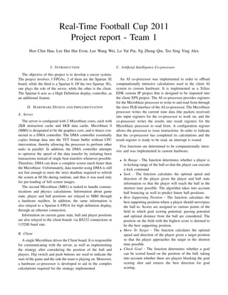
  • 4. Fig. 3. Screenshot of Java Simulator Fig. 2. Java simulator block diagram • Set the initial positions of the players In Attacking mode, a Best Support Position (BSP) will be • Control player movements and kicks calculated every cycle. With the help of the hardware co- • Monitor the server output data by receiving and decoding processor, the algorithm takes into consideration the position the packets using the protocol specifications defined in the of the ball as well as all player positions. The closest player module wiki page to the BSP will be assigned the role of Supporter, and will • Monitor the rate of server to player packets by displaying have to move to the BSP as fast as possible. Meanwhile, the the following parameters: Possessor also tries to dribble to the BSP, while other players • Total packets sent maintain their roles as Markers. • Number of packets sent in the single second Once the Supporter is within range of the BSP, the game • Average rate of sending packets (packets per second) state goes into Passing mode, where the Possessor kicks the • Refresh Rate ( packets per second/11) ball in the direction of the BSP. In this state, the Supporter • Stores the output log in a text file with the values stored chases the ball, while other players maintain their Marker as hex string roles. The Possessor will maintain its heading and speed, as a The program itself incorporates elements of a real-time backup in case the pass is not successful. A countdown is also system (Fig 2), and enabled us to perform simulation of the initialized at the start of the state, and should the Supporter game without the need for a client board, hence allowing the fail to get in range of the ball before the countdown runs out, team develop the server and client in parallel. This values we assume that the pass has failed and the global state returns shown in the screen-shot (See Fig 3) indicates that the hex to Defending mode. values sent out by our server are correct. As illustrated, the At all points in time, the Possessor will attempt to shoot at refresh rate of our server is indeed 25Hz. the goal should it be in range and has clear line-of sight. This criteria is also calculated with the help of the co-processor. B. Python simulation for AI co-processor 2) Communication with co-processor: Driver functions are A python program is written to assist in the debugging of the written for the co-processor so that the client can commu- BSP calculation. The program displays visually the positions nicate with the co-processor. The functions basically write on the field that is possible for the ball to be passed to and the received packets into the input registers, write the correct determines whether a goal scoring opportunity is available. An instruction word into the configuration register and unpack example of the visualization can be seen below: the result from the result register. To run a certain function on In Fig 4, the blue dots represent positions that a pass can be the co-processor, one calls the execution function, and waits made, and the pink lines indicate that goal shots are possible for the completion interrupt to occur using a semaphore. The from that position. Using this visualization, one can determine unpack function is then called to obtain the results from the whether the calculated BSP in the co-processor is correct. result register. As can be seen in the summary report, the co-processor meets the timing constraints of the Microblaze clock (< 20ns IV. T ESTING AND V ERIFICATION minimum period). Approximately 109120 clock cycles are A. Java simulator required in the worse case scenario for the most complex In order to be sure that the server met the requirements operation (BSP calculation), which would result in a delay specified, a separate program was written to process the output of roughly 2ms. This is still way faster than if it were data on a PC. Features incorporated in the program include the implemented on the Microblaze. ability to:
  • 5. VI. L ESSONS L EARNT One major mistake we made was the failure to test the sys- tem under full load. During the testing of the communication threads, we did not send data at the full rate specified, and hence did not foresee the problem of data-loss due to buffer overflow. The issue was discovered only at a much later date, leaving us with hardly any time left for debugging. Being a crucial part of the system, the lack of a stable communication also held back the debugging of the AI. Despite the ability of the hardware co-processor, the software strategy implemented was primitive and untested, which was a huge disappointment. Fig. 4. BSP Visualization in Python In general, we placed too much focus on developing extra features, most notably the high definition display. This left us with little time and manpower to ensure that basic require- Number of Slices: 3372 out of 14752 22% Number of Slice Flip Flops: 2053 out of 29504 6% ments are fulfilled. Number of 4 input LUTs: 6348 out of 29504 21% Number of IOs: 138 VII. C ONCLUSION Number of bonded IOBs: 138 out of 250 55% Number of MULT18X18SIOs: 29 out of 36 80% Despite the setbacks faced, we have gained invaluable Number of GCLKs: 1 out of 24 4% knowledge on real-time operating systems from this project. Minimum period: 17.247ns (Maximum Frequency: 57.981MHz) Not only do we learnt to optimize the code to meet stringent Minimum input arrival time before clock: 13.248ns deadlines, we have also learnt how to configure the hardware Maximum output required time after clock: 10.152ns Maximum combinational path delay: 17.399ns} to deliver maximum performance. This includes the use of instruction and data-caches, as well as the hardware co- V. P OSSIBLE I MPROVEMENTS processor and custom controller for high definition display. A. Communication issues We have also realized the difficulties in debugging a real- The standard protocol assumes that not a single byte of data time system, and the importance of rigorous tests to ensure is lost throughout the entire match, which is a dangerous as- reliability and robustness of the system. sumption to make. In our experience, a single byte loss would In terms of project management, we have learnt the impor- result in corruption to all subsequent data received, and the tance of including buffer periods in our development schedule, only resolution would be to restart the entire match. Such an in case of unforeseen technical complexities. It is also more implementation would be unacceptable for any firm real-time important to meet the basic requirements flawlessly than systems, as it lacks robustness and error-detection/recovery. having extra features. To make things worse, Xilinx has published that the UartLite serial controller has a 8% error rate, which increases with increasing baud-rate used. Hence we propose to improve the communications protocol, with the addition of sentinel flags to the beginning and end of each update packet. This would at least provide a way for client/servers to discover and recover from data loss. The most common cause of data loss is due to buffer overflow on the receive buffers. While we have already imple- mented interrupt service routines to discover incoming data, as well as having the receive thread running at top-priority, the problem can still occur. This issue has been identified to be caused by slow execution of the communication thread, as it code is placed in the DDR section of the memory. As DDR arbitration is still based on a Round-Robin algorithm, the rate at which the thread can execute is variable. We have since learnt to enable a larger instruction cache on the Microblaze 1 of the server, as well as the client Microblaze, and the issue has been resolved. Unfortunately, the realization came after the project presentation, which is a step too late.